2011 MERCEDES-BENZ M-CLASS SUV lock
[x] Cancel search: lockPage 226 of 389

X
Selector wheel : engaged:
brieflypress
selecto rwheel :.
Selector wheel :extends.
X To select: turnselector wheel :until indi-
cator lamp ;comes on.
Off-road indicator =appears in the multi-
function display.
Off-road level 1isset to +3 0mmabove the
highwa ylevel.
Off-road program 1switches to the AUTO
program if you drive faster than 110 km/h.
Off-road program 2 Select off-road program
2for rough terrain,
e.g. for steep and/or uneven terrain or for
drivin gonr ocky terrain.
i Your vehicle has an automatically activa-
ted differential lock for the transfer case. It
con trols the balance between the front and
rear axles.
The differential lock improves the vehicle’s
trac tion. 4ETS (Y page 64)controls the bal-
anc ebetween the two wheels on one axle.
You can only activate off-road program 2
when driving at speeds below 40 km/h. X
Selector wheel : engaged:
briefly press
selector wheel :.
Selector wheel :extends.
X To select: turnselector wheel :until indi-
cator lamp ;lights up.
Off-road indicator =appears in the multi-
function display.
R Off-road level 2isset; the vehicle is
raised by +6 0mmcompared to the high-
way level.
R DSR is switched on.
R The differential lock is closed.
Off-road program 2automatically switches to
off-road program 1ifyou dri vefaster than
45 km/h. LO
WR ANGE off-road gear (vehicles
with th eON&O FFROAD package)
General notes The LOW RANGE off-road gear assists you
when driving off-road and when fording. When
LOW RANGE is engaged, th
eengin e’sp er-
formance characterist icsa nd the gearshifting
characteristics of the automatic transmiss ion
are adapted for thi spurpose. Off-roa
ddriving systems
223Drivingandparki ng Z
Page 228 of 389

From LOW RANGE to HIG
HRANGE
! Only carry out the gear change process if:
R the engin eisrunning
R the transmission is in position N
R you are not driving above 70 km/h
X Press LOW RANG Ebutton :.
Indicato rlamp ;flashes.
When the gear change is complete, indica-
tor lamp ;goes out. In th emultifunction
display, the LOWR ANGE Off message
appears and status indica tor=goes out.
While indica torlamp ;is flashing, you can
cancel the gear change by pressin gLOW
RANGE button :agai n.
Me ssages in th emultif un ction display
If ag ear chang eprocess ha snot been suc-
cessful, th efollowin gmessages may be dis-
played in the multifunction display:
LOW RANGE Max. speed 40 km/h :Y
ou have
been drivin gabove 40 km/h. Indicator
lamp ;also flashes.
X Drive mor eslowly to carr yout the gear
change process.
LO WR ANGE Shift to position N briefly :T
he transmission is in position D
and you ar enow drivin gatbelow 40 km/h.
X Shif tthe transmission to Nto complete the
gear change process.
LOW RANGE Shifting cancelled Please
reactivate :T
he shifting process has not
been completed.
X Maintai nall gear change condition sand
carry out the gea rchange process again.
LO WR ANGE Stop Apply parking brake :
Aw arning ton eisalso heard. The gear change
proces shas not been completed. LOW
RANGE is in the neut ralp osition .There is no
con nectio nbetween the engine and the drive
wheels.
! Do not driv eany further, otherwis eyou
coul ddamage the vehicle's drive train. X
Stop the vehicle. Take into account the
road and traffic conditions when doing this.
X Apply the electric parking brake
(Y page 161).
X Carry out the gear change process again.
If the gear change process has been carried
out, the LOWR ANGE Stop Apply park‐ ing brake message disapp
ears. ON&OFFROAD men
uint he COMAND
display (vehicles wit hthe ON&OFF-
ROA Dpackage)
Yo uc an displ ay some driving systems ,driving
programs and additional information in the
COMAND display. X
Make sure that th ekey is in position 2in
the ignition lock.
X Make sure that COMAN DOnline is activa-
ted, see the separate COMAND operating
instructions.
X Pres sthe : func tion button.
The corresponding displays appear in the
CO MAN Ddisplay:
R level control
R steering angle
R vehicle' sangle of inclination
R uphill or downhil lgradient in percentage
R on- road/off-road program selected
R condition of the differential lock for the
transfer case
R the LOW RANGE off-road gear is selected Off-road driving systems
225Drivingand parking Z
Page 229 of 389

R
cond ition of the LOW RAN GEoff-r oad
gear
R the on-roa dtraile rprogram is selected Tow
inga trailer Note
sont owingatrailer
Important safety notes G
WARNING
When reversing the vehicl etowards the
trailer, make sure there is nobod ybetween
the trailer and the vehicle.
Couple and uncoupl ethe trailer carefully .If
you do not couple the trailer to the towing
vehicle correctly, the trailer coul dbecome
detached.
Make sure that the following values are not
exceeded:
R the permissible trailer drawbar noseweight
R the permissible trailer load
R the permissible rear axle load of the towing
vehicle
R the maximu mpermissible gross vehicle
weight of both the towing vehicle and the
trailer
You will fin dthe applicable permissible val-
ues, whic hmust not be exceeded ,inthe vehi-
cle documen ts.
You will find the values approved by the man-
ufacturer on the vehicle identification plates
and those for the towing vehicle in the "Tech-
nical data" section. G
WARNING
If the Checktrailer hitch locking mechanism message appears in th
emulti-
function display while the vehicle is in motion,
pull over immediately and check whethe rthe
ball coupling is correctly engaged. G
WARNING
When towin gatrailer, you rvehicle' shandling
characteristics will be different in comparison
to when driving without atrailer.
Th ev ehicle/ trailer combination:
R is heavier
R is restricted in its acceleration and gradi-
ent-climbin gcapability
R has an increased braking distance
R is affected more by stron gcrosswinds
R demand smore sensitive steering
R has alarger turnin gcircle
As aresult, the handlin gcharacteristic smay
be impaired and you may lose control of the
vehicle. This could lead to an accident with
serious or even fatal injuries.
When towing atrailer, alway sadjust your
speed to the current road and weather con-
ditions. Do not exceed the maximum permis-
sible speed for your vehicle/trailer combina-
tion. G
WARNING
Never depress the brak epedal continuously
while the vehicle is in motion ,e.g. never cause
the brakes to rub by applying cons tant slight
pedal pressure. Thi scauses the brake system
to overheat, increases the braking distance
and can lead to the brakes failing completely. G
WARNING
On no account shoul dyou attempt to dra wthe
vehicle/ trailer combination out by increasing
speed. G
WARNING
If you exceed the maximum noseweight when
using acarrier system on the ball coupling:
R the carrier system may be thrown around.
R the ball coupling and the carrier system
may become detached from the vehicle.
As aresult, you may injure others or cause an
accident. 226
Towing
atrailerDriving and parking
Page 231 of 389
Driving tips
R
Maintain agreater distanc efrom th evehi-
cle in front than when driv ingw ithou ta
trailer.
R Avoid braking abruptly .Ifpossible, brake
gentl yatfirst to allow the trailer to run on.
Then, increase the brakin gforc erapidly.
R The values given for gradient-climbing
capabilities from astandstill refer to sea
level. Whe ndriving in mountainou sareas,
note that th epower outpu tofthe engine,
and consequen tlyt he vehicle' sgradient-
climbing capability ,decrease with increas-
ing altitude.
If the trailer swings from side to side:
X Do not accelerate.
X Do not coun ter-steer.
X Brake if necessary. Folding ou
tthe bal lcoupling G
WARNING
Make sure that no persons or animals are in
the pivoting range of the ball coupling. Other-
wise, they could be injured.
Before you can tow atrailer wit hyour vehicle,
you must fold out the ball coupling.
X Make sure that the vehicle is stationary.
X Open the tailgate. G
WARNING
Make sur ethat the ball coupling is engaged,
either in its folded-ou torfolded-i nposition.
The indicator lam ponthe release knob is off.
Do not pull the ball coupling release switch
when atrailer is coupled or abicycle rack is
fitted.
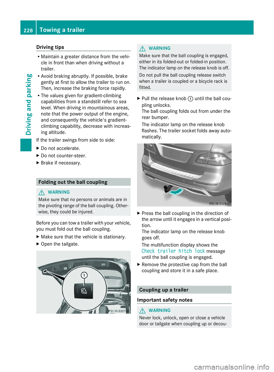
X Pull the release knob :until the ball cou-
pling unlocks.
The ball coupling folds out from under the
rear bumper.
The indicator lamp on the release knob
flashes. The trailer socket folds away auto-
matically. X
Press the ball coupling in the direction of
the arrow until it engages in avertical posi-
tion.
The indicator lam ponthe release knob
goes off.
The multifunc tion display shows the
Chec ktrailer hitch lock message
until th eball coupling is engaged.
X Remove the protective cap from the ball
coupling and store it in asafe place. Coupling up
atrai ler
Impor tant safety notes G
WARNI
NG
Neve rlock, unlock, open or close avehicle
door or tailgat ewhen coupling up or decou- 228
Towing
atrailerDriving and parking
Page 233 of 389
Vehicles with the AIRMATIC package
X
Make sure tha tthe transmission is in posi-
tion P.
X Engage the electric parkin gbrake.
X Start th eengine.
X Clos ethe doors and tailgate.
X Secur ethe trailer against rolling away.
X Remove the trailer cable and decouple the
trailer.
X Switc hoff th eengine. Folding in the ball coupling
i Fold the ball coupling back in if you are
not using the trailer tow hitch.
X Make sure that the vehicl eisstationary and
the trailer cables are disconnected.
X Place the protective cap on the ball cou-
pling.
X Ope nthe tailgate. X
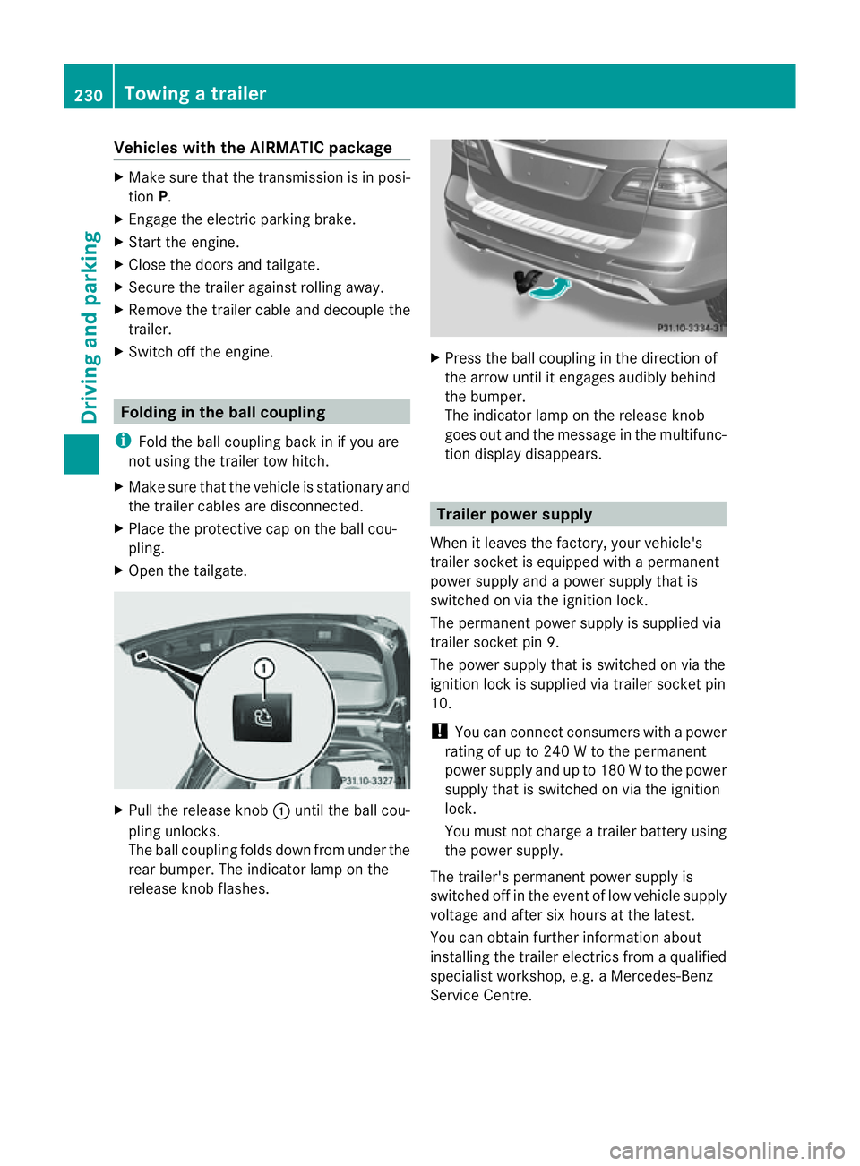
Pull the release knob :until the ball cou-
plin gunlocks.
The ball coupling folds dow nfrom under the
rea rbumper. The indicator lamp on the
release knob flashes. X
Press the ball coupling in the direction of
the arrow until it engage saudibly behind
the bumper.
The indicator lamp on the release knob
goes out and the messag einthe multifunc-
tion display disappears. Trailer power supply
When it leaves the factory ,your vehicle's
trailer socket is equipped with apermanent
power supply and apower supply that is
switched on via the ignition lock.
The permanen tpower supply is supplied via
trailer socket pin 9.
The power supply that is switched on via the
ignition lock is supplied via trailer socket pin
10.
! You can con nect consumers with apower
ratin gofupto2 40Wtot he permanent
power supply and up to 18 0Wto the power
supply that is switched on via the ignition
lock.
You must not charge atrailer battery using
th ep ower supply.
The trailer's permanen tpower supply is
switched off in the even toflow vehicle supply
voltage and after six hour satthe latest.
You can obtai nfurther information about
installing the trailer electrics from aqualified
specialist workshop, e.g. aMercedes-Benz
Ser vice Centre. 230
Towing
atrailerDriving and parking
Page 234 of 389
X
To switc hthe conn ected powe rsupply
on or off: turn thekey in the ignition lock
to position 2or 0respectivel y. Bulb failure indi
cator for LE Dlamps
i If LED lamps are fitte dinthe trailer, an
error message ma yappear in the multi-
function display even if there is no fault. The
reason for the error message may be that
the current has fallen below the minimum
of 50 milliamper es(mA).
To ensure reliabl eoperation of the bul bfailure
indicator, each LED chai ninthe trailer lighting
must be guaranteed aminimum current of
50 mA. Trailer with 7-pin connector
Genera linforma tion If your trailer has
a7-pin connector, you can
connect it to the 13-pin socket on the ball
coupling using an adapter or, if necessary, an
adapter cable .Both of these can be obtained
at aq ualified specialist workshop, e.g. at a
Mercedes-Ben zService Centre.
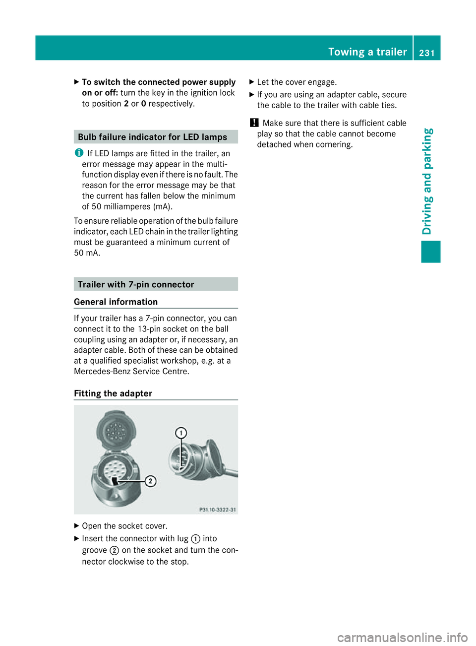
Fitting the adapter X
Open the socket cover.
X Insert the connector with lug :into
groove ;on the socket and tur nthe con-
nec torc lockwise to the stop. X
Let the cover engage.
X If you are using an adapter cable, secure
the cable to the trailer with cable ties.
! Make sure that there is sufficient cable
play so that the cable cannot become
detached when cornering. Towing
atrailer
231Driving andparki ng Z
Page 235 of 389
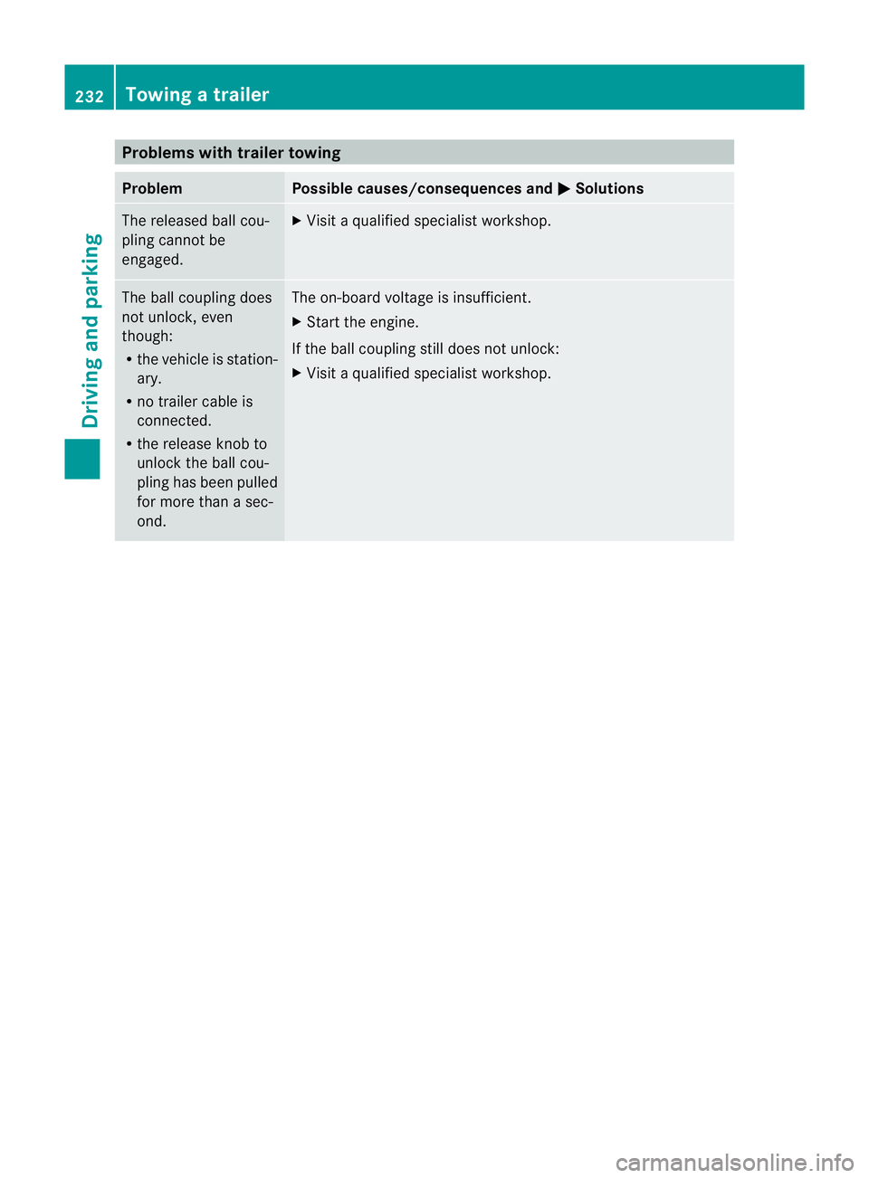
Problems wit
htrailer towing Problem Possible causes/consequences and
M Solutions
The released ball cou-
pling cannot be
engaged. X
Visit aqualified specialist workshop. The ball coupling does
not unlock, even
though:
R the vehicle is station-
ary.
R no trailer cable is
connected.
R the release knob to
unlock the ball cou-
pling has been pulled
for more than asec-
ond. The on-boar
dvoltage is insufficient.
X Start the engine.
If the ball coupling still does not unlock:
X Visit aqualified specialist workshop. 232
Towin
gatrailerDriving and parking
Page 238 of 389
or on bridges. If you do not adapt your driving
style to the conditions, the vehicle coul dskid.
For this reason, adapt your driving style and
speed to the weather conditions.
Changes in the outside temperature are dis-
playe dafter ashort delay. Speedometer wit
hsegments
The segment sinthe speedometer indicate
whic hspeed range is available.
Cruise control (Y page 170) activated:
The segment slight up from the stored speed
to the maximum speed.
Variable SPEEDTRONI C(Ypage 172) activa-
ted:
The segment slight up from the start of the
scale to the selected limit speed.
DISTRONIC PLU S(Ypage 174) activated:
One or two segment sinthe set speed range
light up.
DI ST RONIC PLUS detects avehicle in front:
The segment sbetween the speed of the vehi-
cle in front and the stored speed light up. Opera
ting th eon-board computer
Overview The on-board computer is activated as soon
as you tur nthe key to position 1in the ignition
lock.
You can con trol the multifunc tion display and
the settings in the on-boar dcomputer using
the button sonthe multifunc tion steering
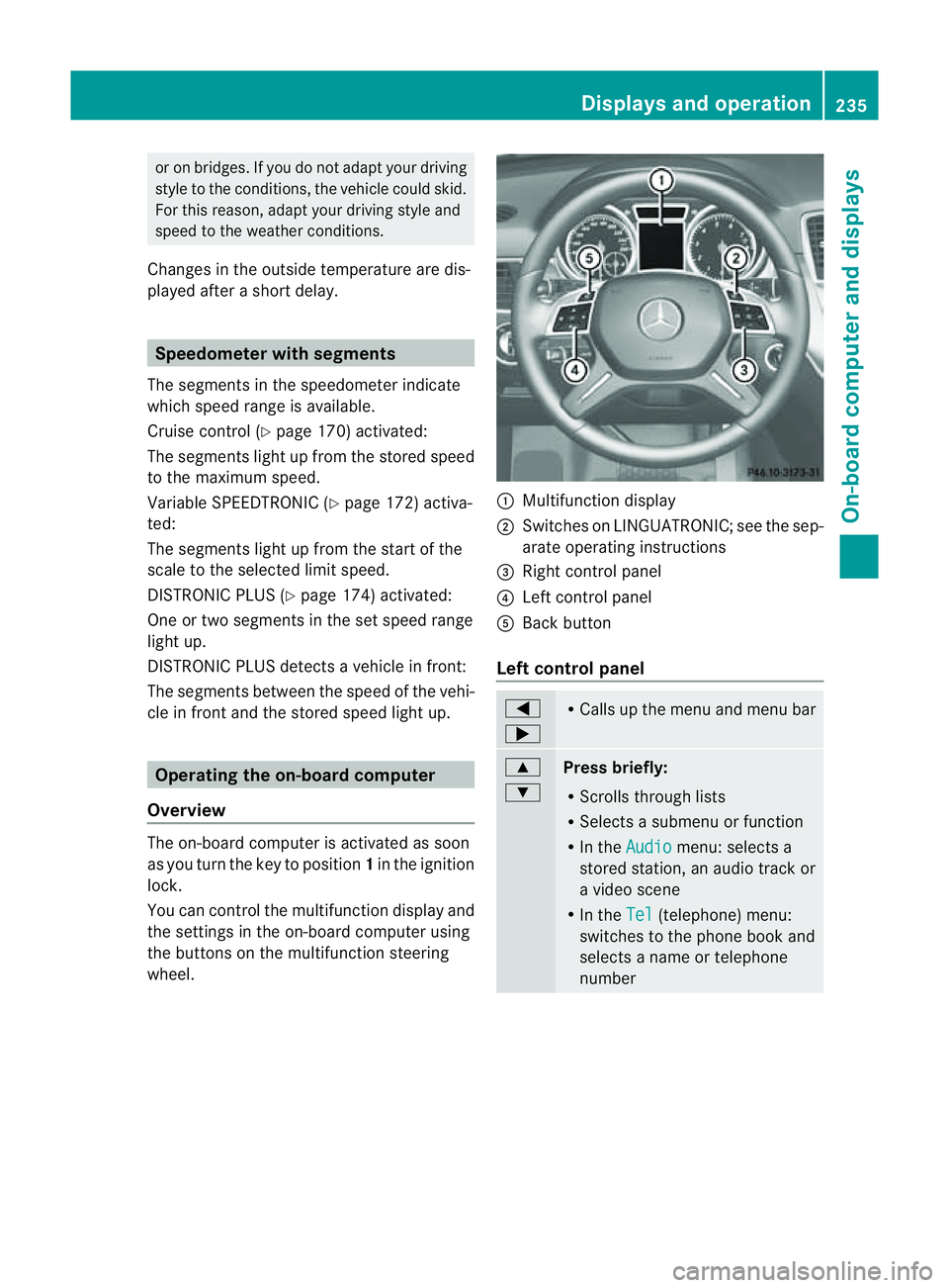
wheel. :
Multifunc tion display
; Switches on LINGUATRONIC ;see the sep-
arate operating instructions
= Right control panel
? Leftcontrol panel
A Bac kbutton
Left control panel =
; R
Call supt he men uand menu bar 9
:
Pres
sbriefly:
R Scrolls throug hlists
R Select sasubmenu or function
R In the Audio menu: selects a
stored station, an audio track or
av ideo scene
R In the Tel (telephone) menu:
switches to the phone book and
selects aname or telephone
number Displays and operation
235On-boardcomputer and displays Z