2011 MERCEDES-BENZ C-CLASS COUPE service
[x] Cancel search: servicePage 190 of 373

behind, in fron
tofand next to the vehicle. You
could otherwise endanger yoursel fand oth-
ers. G
WARNING
Unde rthe following circumstances, the
reversing camera will not function, or will
function in a limited manner:
R if the boot lid is open
R in heavy rain, snow or fog
R at night or in very dark places
R if the camera is exposed to very bright light
R if the area is lit by fluorescent light (the dis-
play may flicker)
R if there is a sudden change in temperature,
e.g. when driving into a heated garage in
winter
R if the camera lens is dirty or obstructed
R if the rear of your vehicle is damaged. In this
event, have the camera position and setting
checked at a qualified specialist workshop.
Mercedes-Ben zrecommends that you use
a Mercedes-Benz Service Centre for this
purpose.
Do not use the reversing camera in these
types of situation .You could otherwise injure
others or damage objects and your vehicle
while you are parking.
Activating the reversing camera X
Make sure that the key is in position 2in
the ignition lock.
X Make sure that the "Reversing camera"
function is selected in COMAND Online
(see the separate operating instructions for
COMAND Online).
X Engage reverse gear.
The area behind the vehicle is shown in the
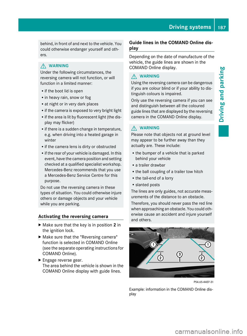
COMAND Online display with guide lines. Guide lines in the COMAND Online dis-
play Depending on the date of manufacture of the
vehicle, the guide lines are shown in the
COMAND Online display.
G
WARNING
Using the reversing camera can be dangerous
if you are colour blind or if your ability to dis-
tinguish colours is impaired.
Only use the reversing camera if you can see
and distinguish between all the coloured
guide lines that are displayed by the reversing
camera in the COMAND Online display. G
WARNING
Please note that objects not at ground level
may appear to be further away than they
actually are. These include:
R the bumper of a vehicle that is parked
behind your vehicle
R a trailer drawbar
R the ball coupling of a trailer tow hitch
R the tail-end of a lorry
R slanted posts
The lines are only guides, not accurate meas-
urements of the distance to an obstacle.
Therefore, you should never pass the red line
when approaching an obstacle. You could oth-
erwise cause an accident and injure yourself
and others. Example: information in the COMAND Online dis-
play Driving systems
187Driving and parking Z
Page 194 of 373

Monitoring range of the sensors
Blind Spot Assist monitors the area up to
three metres behind yourv ehicle and directly
nextt o your vehicle, as shown in the diagram. G
WARNING
Blind Spot Assist monitors certain areas in the
immediate vicinity of your vehicle. Vehicles
that approach and drive past at high speeds
are not detected. There is no display and no
warning.
If the lanes are very wide, it may not be pos-
sible to monitor the complete width of the
neighbouring lane. For this reason, vehicles in
the next lane may not be detected, especially
if they are driving in a staggered formation in
different lanes. This may be the case if vehi-
cles are driving at the edge of their lane that
is furthest away from your vehicle.
Always pay attention to traffic conditions and
your surroundings. Otherwise, you may fail to
recognise dangers in time, cause an accident
and injure yourself and others.
If the lanes are narrow, the system may be
unable to distinguish the neighbouring lane
from the one beyond it. For this reason, vehi-
cles in the farther lane may be indicated,
especially if the vehicles are driving in a stag-
gered formation in different lanes. In particu-
lar, this may be the case if the vehicles are driving at the edge of their lane nearest your
vehicle.
Due to the nature of the system:
R
warnings may be issued in error when driv-
ing close to crash barriers or similar solid
lane borders.
R warnings may be interrupted when driving
alongside particularly long vehicles, for
example lorries, for a prolonged time.
The two sensors for Blind Spot Assist are
integrated into the sides of the rear bumper.
Make sure that the bumper is free of dirt, ice
or slush around the sensors. For example, the
radar sensors must not be covered by cycle
racks or overhanging loads. Following a
severe impact or in the event of damage to
the bumpers, have the function of the radar
sensors checked at a qualified specialist
workshop, e.g. a Mercedes-Benz Service
Centre. Blind Spot Assist may otherwise not
work properly.
Indicator and warning display :
Yellow indicator lamp/red warning lamp
If Blind Spot Assist is switched on, indicator
lamp :in the exterior mirrors lights up yel-
low up to a speed of 30 km/h. At speeds
above 30 km/h, the indicator lamp goes out
and Blind Spot Assist is operational.
If a vehicle is detected within the monitoring
range of Blind Spot Assist at speeds above
30 km/h, warning lamp :on the corre-
sponding side lights up in red. This warning is
always emitted when a vehicle enters the
blind spot monitoring range from behind or Driving systems
191Driving and parking Z
Page 198 of 373

the next lane may not be detected, especially
if they are driving in a staggered formation.
This may be the case if vehicles are driving at
the edge of their lane tha tis furthest away
from your vehicle.
Always pay attention to traffic conditions and
your surroundings. Otherwise, you may fail to
recognise dangers in time, cause an accident
and injure yourselfa nd others.
If the lanes are narrow, vehicles driving in the
lane beyond the lane next to your vehicle may
be indicated, especially if the vehicles are not
driving in the middle of thei rlane .This may
be the case if the vehicles are driving on the
inner side of their lane.
Due to the nature of the system:
R warnings may be issued in error when driv-
ing close to crash barriers or similar solid
lane borders.
R warnings may be interrupted when driving
alongside particularly long vehicles, for
example lorries, for a prolonged time.
Two Active Blind Spot Assist radar sensors
are integrated into the front and rear bumpers
respectively. An additional radar sensor is
located behind the cover in the radiator grille.
Make sure that the bumpers are free of dirt,
ice or slush around the sensors. The rear sen-
sors must not be covered, for example by
cycle racks or overhanging loads. Following a
severe impact or in the event of damage to
the bumpers, have the function of the radar
sensors checked at a qualified specialist
workshop, e.g. a Mercedes-Ben zService
Centre. Active Blind Spot Assist may other-
wise fail to work correctly. Indicator and warning display :
Yellow indicator lamp/red warning lamp
When Active Blind Spot Assist is activated,
indicator lamp :in the exterior mirrors lights
up in yellow at speeds of up to 30 km/h. At
speeds above 30 km/h, the indicator lamp
goes out and Active Blind Spot Assist is
operational.
If a vehicle is detected within the monitoring
range of Blind Spot Assist at speeds above
30 km/h, warning lamp :on the corre-
sponding side lights up red. This warning is
always emitted when a vehicle enters the
blind spot monitoring range from behind or
from the side. When you overtake a vehicle,
the warning only occurs if the difference in
speed is less than 12 km/h.
The yellow indicator lamp goes out if reverse
gear is engaged. Active Blind Spot Assist is
then no longer active.
The brightness of the indicator/warning
lamps is adjusted automatically according to
the ambient light. G
WARNING
Active Blind Spot Assist is not active at speeds
below 30 km/h. The indicator lamps in the
exterior mirrors are yellow. Vehicles in the
monitoring range are then not indicated.
Always pay attention to traffic conditions and
your surroundings. Otherwise, you may fail to
recognise dangers in time, cause an accident
and injure yourself and others. Driving systems
195Driving and parking Z
Page 206 of 373

X
Place the protective cap on the ball cou-
pling.
The release wheel is located behind the left-
hand side trim panel in the boot. Coupé
X
To open the cover: turn handle:anti-
clockwise and fold down cover ;.X
Pull out release wheel =.
X Turn release wheel =anti-clockwise.
The ball coupling unlocks and lowers. Indi-
cator lamp ?flashes. X
Press the ball coupling in the direction of
the arrow until it engages behind the
bumper.
Indicator lamp ?goes out and the mes-
sage in the multifunction display disap-
pears. Trailer power supply
When it leaves the factory, your vehicle's
trailer socket is equipped with a permanent
power supply and a power supply that is
switched on via the ignition lock.
The permanen tpower supply is supplied via
trailer socket pin 9.
The power supply that is switched on via the
ignition lock is supplied via trailer socket pin
10.
! You can connect consumers with a power
rating of up to 240 W to the permanent
power supply and up to 180 W to the power
supply that is switched on via the ignition
lock.
You must not charge a trailer battery using
the power supply.
The trailer's permanent power supply is
switched off in the event of low vehicle supply
voltage and after six hours at the latest.
You can obtain further information about
installing the trailer electrics from a qualified
specialist workshop, e.g. aMercedes-Benz
Service Centre.
X To switch the connected power supply
on or off: turn the key in the ignition lock
to position 2or 0respectively. Bulb failure indicator for LED lamps
i If LED lamps are fitted in the trailer, an
error message may appear in the multi-
function display even if there is no fault. The
reason for the error message may be that
the curren thas falle nbelow the minimum
of 50 milliamperes (mA). Trailer towing
203Driving and parking Z
Page 207 of 373

To ensure reliable operation of the bulb failure
indicator, each LED chain in the trailer lighting
must be guaranteed a minimum current of
50 mA. Trailer with 7-pin connector
General information If your trailer has a 7-pin connector, you can
connect it to the 13-pin socket on the ball
coupling using an adapter or, if necessary, an
adapter cable. Both of these can be obtained
at a qualified specialist workshop, e.g. at a
Mercedes-Benz Service Centre.
Fitting the adapter X
Open the socket cover.
X Insert the connector with lug :into
groove ;on the socket and turn the con-
nector clockwise to the stop.
X Let the cover engage.
X If you are using an adapter cable, secure
the cable to the trailer with cable ties.
! Make sure that there is sufficient cable
play so that the cable cannot become
detached when cornering. 204
Trailer towingDriving and parking
Page 209 of 373

Useful information
i This Owner's Manual describes all models
and all standard and optional equipment
available to your vehicle at the time of pub-
lication of the Owner's Manual. Country-
specific deviations are possible. Please
note that your vehicle may not be equipped
with all features described. This also
applies to safety-relevan tsystems and
functions.
i Please read the information on qualified
specialist workshops (Y page 26).Important safety notes
You will find an illustration of the instrument
cluster in the "At a glance" section
(Y page 32). G
WARNING
Only use the on-board computer when road
and traffic conditions permit .You would oth-
erwise be distracted and unable to concen-
trate properly on driving, and could cause an
accident. G
WARNING
If the instrument cluster or multifunction dis-
play fails, no messages can be displayed.
This means that you will not see information
about the driving situation, such as the speed,
outside temperature, warning/indicator
lamps, display messages or system failures.
Handling characteristics may be affected.
Adapt your driving style and speed accord-
ingly.
Immediately consult a qualified specialist
workshop which has the necessary specialist
knowledge and tools to carry out the work
required. Mercedes-Benz recommends that
you use a Mercedes-Benz Service Centre for
this purpose. In particular, work relevant to
safety or on safety-related systems must be
carried out at a qualified specialist workshop. G
WARNING
The on-board computer only records and dis-
plays malfunctions and warnings from certain
systems. For this reason, you should always
make sure that your vehicle is safe to use. You
could otherwise cause an accident by driving
an unsafe vehicle. G
WARNING
The operating safety of your vehicle could be
jeopardised if maintenance work is carried
out incorrectly. As aresult, you could lose
control of the vehicle and cause an accident.
In addition, the safety systems may no longer
be able to protec tyou or others as they are
designed to do.
Always have maintenance work carried out at
a qualified specialist workshop. The qualified
specialist workshop must have the necessary
specialist knowledge and tools to carry out
the work required. Mercedes-Benz recom-
mends that you use a Mercedes-Benz Service
Centre for this purpose. In particular, work
relevant to safety or on safety-related sys-
tems must be carried out at a qualified spe-
cialist workshop. Displays and operation (4-button mul-
tifunction steering wheel)
Coolant temperature gauge
The coolant temperature gauge is in the
instrument cluster on the left-hand side.
Under normal operating conditions and with
the specified coolant level, the coolant tem-
perature may rise to 120 †.
The coolant temperature may rise to the top
end of the scale at high outside temperatures
and on long uphill stretches. Rev counter
The red band in the rev counter indicates the
engine's overrevving range. 206
Displays and operation (4-button multifunction steering wheel)On-board computer and displays
Page 210 of 373

!
Do not drive in the overrevving range.
Doing so will damage the engine.
The fuel supply is interrupted to protect the
engine when the red band is reached. Outside temperature display
The outside temperature display is in the
instrument cluster (Y page 32).G
WARNING
At temperatures just above freezing point, the
street may be icy, especially in wooded areas
or on bridges. If you do not adapty our driving
style to the conditions, the vehicle could skid.
For this reason, adapt your driving style and
speed to the weather conditions.
Changes in the outside temperature are dis-
played after a short delay. Operating the on-board computer
The on-board computer is activated as soon
as you turn the key to position 1in the ignition
lock. You can use the on-board computer to
call up information relating to your vehicle
and to make and adjust settings.
i You can have certain functions set at a
qualified specialist workshop, e.g. a
Mercedes-Benz Service Centre.
Example:
R automatic door lock
R speed limit for winter tyres
You can obtain information about this at
any Mercedes-Benz Service Centre.
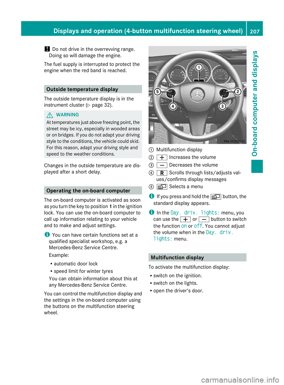
You can control the multifunction display and
the settings in the on-board computer using
the buttons on the multifunction steering
wheel. :
Multifunction display
; W Increases the volume
= X Decreases the volume
? C Scrolls through lists/adjusts val-
ues/confirms display messages
A V Selects a menu
i If you press and hold the Vbutton, the
standard display appears.
i In the Day. driv. lights: menu, you
can use the WorX button to switch
the function on or
off .Y
ou cannot adjust
the volume when in the Day. driv. lights: menu.
Multifunction display
To activate the multifunction display:
R switch on the ignition.
R switch on the lights.
R open the driver's door. Displays and operation (4-button multifunction steering wheel)
207On-board computer and displays Z
Page 212 of 373

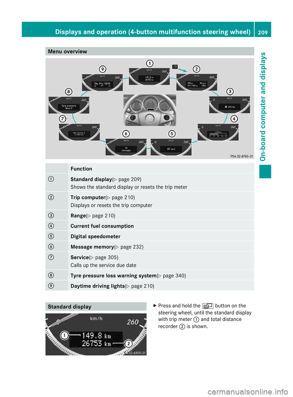
Menu overview
Function
:
Standard display
(Ypage 209)
Shows the standard display or resets the trip meter ;
Trip computer
(Ypage 210)
Displays or resets the trip computer =
Range(Y
page 210) ?
Current fuel consumption
A
Digital speedometer
B
Message memory(Y
page 232)C
Service(Y
page 305)
Calls up the service due date D
Tyre pressure loss warnin
gsystem(Y page 340) E
Daytime driving lights(Y
page 210)Standard display X
Press and hold the Vbutton on the
steering wheel, until the standard display
with trip meter :and total distance
recorder ;is shown. Displays and operation (4-button multifunction steering wheel)
209On-board computer and displays Z