2011 INFINITI QX56 ground
[x] Cancel search: groundPage 3329 of 5598
INL-62
< DTC/CIRCUIT DIAGNOSIS >
STEP LAMP CIRCUIT
STEP LAMP CIRCUIT
DescriptionINFOID:0000000006216073
Controls the step lamp (ground side) to turn the step lamp ON and OFF.
Component Function CheckINFOID:0000000006216074
CAUTION:
Before performing the diagnosis, check that the following is normal.
Interior room lamp power supply
Step lamp bulb
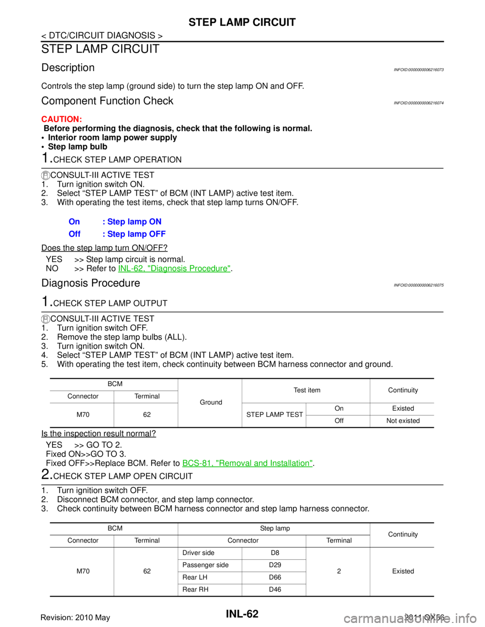
1.CHECK STEP LAMP OPERATION
CONSULT-III ACTIVE TEST
1. Turn ignition switch ON.
2. Select “STEP LAMP TEST” of BCM (INT LAMP) active test item.
3. With operating the test items, c heck that step lamp turns ON/OFF.
Does the step lamp turn ON/OFF?
YES >> Step lamp circuit is normal.
NO >> Refer to INL-62, "
Diagnosis Procedure".
Diagnosis ProcedureINFOID:0000000006216075
1.CHECK STEP LAMP OUTPUT
CONSULT-III ACTIVE TEST
1. Turn ignition switch OFF.
2. Remove the step lamp bulbs (ALL).
3. Turn ignition switch ON.
4. Select “STEP LAMP TEST” of BCM (INT LAMP) active test item.
5. With operating the test item, check c ontinuity between BCM harness connector and ground.
Is the inspection result normal?
YES >> GO TO 2.
Fixed ON>>GO TO 3.
Fixed OFF>>Replace BCM. Refer to BCS-81, "
Removal and Installation".
2.CHECK STEP LAMP OPEN CIRCUIT
1. Turn ignition switch OFF.
2. Disconnect BCM connector, and step lamp connector.
3. Check continuity between BCM harness connector and step lamp harness connector.
On : Step lamp ON
Off : Step lamp OFF
BCM
Ground Test item Continuity
Connector Terminal
M70 62 STEP LAMP TEST On Existed
Off Not existed
BCM Step lamp Continuity
Connector Terminal Connector Terminal
M70 62 Driver side D8
2 Existed
Passenger side D29
Rear LH D66
Rear RH D46
Revision: 2010 May2011 QX56
Page 3330 of 5598
STEP LAMP CIRCUITINL-63
< DTC/CIRCUIT DIAGNOSIS >
C
DE
F
G H
I
J
K
M A
B
INL
N
O P
Is the inspection result normal?
YES >> Replace step lamp.
NO >> Repair or replace harnesses.
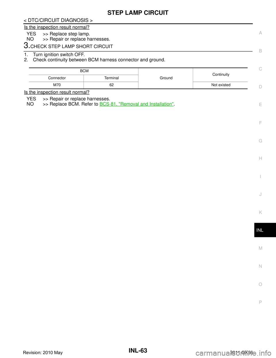
3.CHECK STEP LAMP SHORT CIRCUIT
1. Turn ignition switch OFF.
2. Check continuity between BCM harness connector and ground.
Is the inspection result normal?
YES >> Repair or replace harnesses.
NO >> Replace BCM. Refer to BCS-81, "
Removal and Installation".
BCM
GroundContinuity
Connector Terminal
M70 62 Not existed
Revision: 2010 May2011 QX56
Page 3331 of 5598
INL-64
< DTC/CIRCUIT DIAGNOSIS >
PUDDLE LAMP CIRCUIT
PUDDLE LAMP CIRCUIT
DescriptionINFOID:0000000006216076
Controls the puddle lamp (ground side) to turn the puddle lamp ON and OFF.
Diagnosis ProcedureINFOID:0000000006216077
CAUTION:
Before performing the diagnosis, check that the following is normal.
Interior room lamp power supply
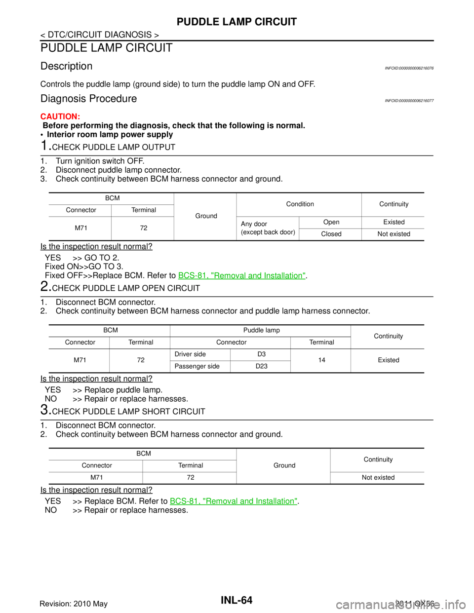
1.CHECK PUDDLE LAMP OUTPUT
1. Turn ignition switch OFF.
2. Disconnect puddle lamp connector.
3. Check continuity between BCM harness connector and ground.
Is the inspection result normal?
YES >> GO TO 2.
Fixed ON>>GO TO 3.
Fixed OFF>>Replace BCM. Refer to BCS-81, "
Removal and Installation".
2.CHECK PUDDLE LAMP OPEN CIRCUIT
1. Disconnect BCM connector.
2. Check continuity between BCM harness connector and puddle lamp harness connector.
Is the inspection result normal?
YES >> Replace puddle lamp.
NO >> Repair or replace harnesses.
3.CHECK PUDDLE LAMP SHORT CIRCUIT
1. Disconnect BCM connector.
2. Check continuity between BCM harness connector and ground.
Is the inspection result normal?
YES >> Replace BCM. Refer to BCS-81, "Removal and Installation".
NO >> Repair or replace harnesses.
BCM
Ground Condition Continuity
Connector Terminal
M71 72 Any door
(except back door)Open Existed
Closed Not existed
BCM Puddle lamp Continuity
Connector Terminal Connector Terminal
M71 72 Driver side D3
14 Existed
Passenger side D23
BCM
GroundContinuity
Connector Terminal
M71 72 Not existed
Revision: 2010 May2011 QX56
Page 3332 of 5598

PUSH-BUTTON IGNITION SWITCH ILLUMINATION CIRCUIT
INL-65
< DTC/CIRCUIT DIAGNOSIS >
C
D E
F
G H
I
J
K
M A
B
INL
N
O P
PUSH-BUTTON IGNITION SWIT CH ILLUMINATION CIRCUIT
Component Function CheckINFOID:0000000006265016
1.CHECK PUSH-BUTTON IGNITION SWITCH ILLUMINATION OPERATION
CONSULT-III ACTIVE TEST
1. Turn the ignition switch ON.
2. Select “ENGINE SW ILLUMI” of BCM (I NTELLIGENT KEY) active test item.
3. With operating the test items, check that the pus h-button ignition switch illumination turns ON/OFF.
Does the push-button ignition switch illumination turn ON/OFF?
YES >> Push-button ignition switch illumination circuit is normal.
NO >> Refer to INL-65, "
Diagnosis Procedure".
Diagnosis ProcedureINFOID:0000000006265017
1.CHECK PUSH-BUTTON IGNITION SWITCH ILLUMINATION POWER SUPPLY OUTPUT
1. Turn ignition switch OFF.
2. Lighting switch OFF.
3. Disconnect push-button ignition switch connector.
4. Check voltage between push-button ignition switch harness connector and ground.
Is the inspection result normal?
YES >> GO TO 4.
NO >> GO TO 2.
2.CHECK PUSH-BUTTON IGNITION SWITCH ILLU MINATION POWER SUPPLY OPEN CIRCUIT
1. Turn the ignition switch OFF.
2. Disconnect BCM connector.
3. Check continuity between BCM harness connector and the push-button ignition switch harness connector.
Is the inspection result normal?
YES >> GO TO 3.
NO >> Repair or replace harnesses.
3.CHECK PUSH-BUTTON IGNITION SWITCH ILLU MINATION POWER SUPPLY SHORT CIRCUIT
Check continuity between BCM harness connector and ground.
Is the inspection result normal?
YES >> Replace BCM. Refer to BCS-81, "Removal and Installation".
On : Push-button ignition
switch illumination ON
Off : Push-button ignition switch illumination OFF
(+)
(–) Condition Vo l ta g e
(Approx.)
Push-button ignition switch
Connector Terminal
M101 3 Ground Push-button ignition
switch illuminationON Condition 12 V
OFF Condition 0 V
BCM Push-button ignition switch Continuity
Connector Terminal Connector Terminal
M71 90 M101 3 Existed
BCM GroundContinuity
Connector Terminal
M71 90 Not existed
Revision: 2010 May2011 QX56
Page 3333 of 5598
INL-66
< DTC/CIRCUIT DIAGNOSIS >
PUSH-BUTTON IGNITION SWITCH ILLUMINATION CIRCUIT
NO >> Repair or replace harnesses.
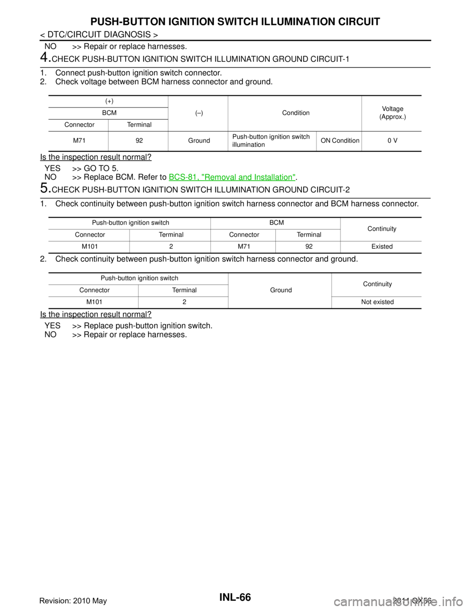
4.CHECK PUSH-BUTTON IGNITION SWITCH ILLUMINATION GROUND CIRCUIT-1
1. Connect push-button ignition switch connector.
2. Check voltage between BCM harness connector and ground.
Is the inspection result normal?
YES >> GO TO 5.
NO >> Replace BCM. Refer to BCS-81, "
Removal and Installation".
5.CHECK PUSH-BUTTON IGNITION SWIT CH ILLUMINATION GROUND CIRCUIT-2
1. Check continuity between push-button ignition switch harness connector and BCM harness connector.
2. Check continuity between push-button ignition switch harness connector and ground.
Is the inspection result normal?
YES >> Replace push-button ignition switch.
NO >> Repair or replace harnesses.
(+) (–) Condition Vo l ta g e
(Approx.)
BCM
Connector Terminal
M71 92 Ground Push-button ignition switch
illuminationON Condition 0 V
Push-button ignition switch BCM
Continuity
Connector Terminal Connector Terminal
M101 2 M71 92 Existed
Push-button ignition switch GroundContinuity
Connector Terminal
M101 2 Not existed
Revision: 2010 May2011 QX56
Page 3375 of 5598
INT-26
< REMOVAL AND INSTALLATION >
FLOOR TRIM
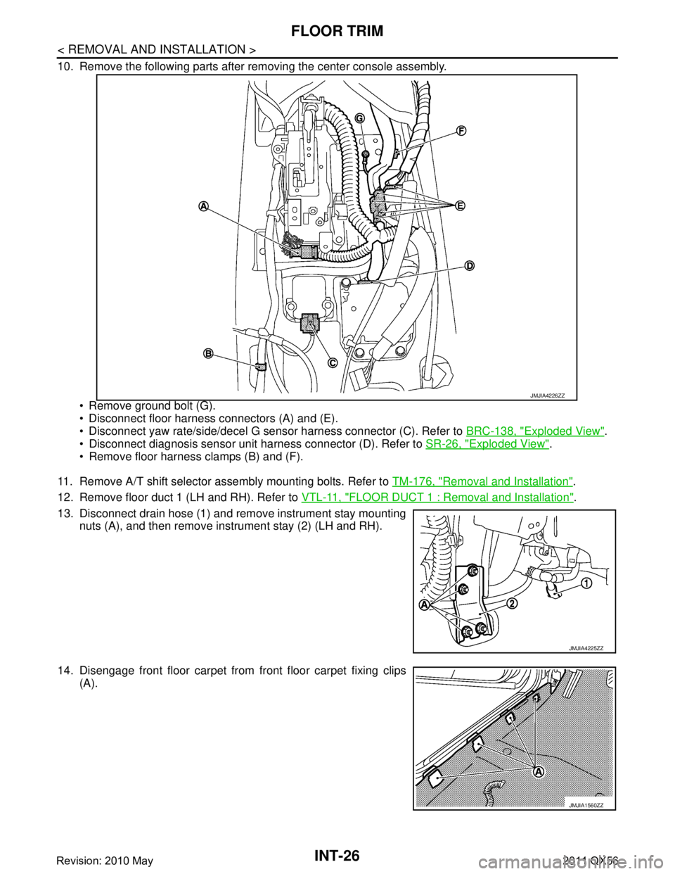
10. Remove the following parts after removing the center console assembly. Remove ground bolt (G).
Disconnect floor harness connectors (A) and (E).
Disconnect yaw rate/side/decel G sensor harness connector (C). Refer to BRC-138, "
Exploded View".
Disconnect diagnosis sensor unit harness connector (D). Refer to SR-26, "
Exploded View".
Remove floor harness clamps (B) and (F).
11. Remove A/T shift selector assembly mounting bolts. Refer to TM-176, "
Removal and Installation".
12. Remove floor duct 1 (LH and RH). Refer to VTL-11, "
FLOOR DUCT 1 : Removal and Installation".
13. Disconnect drain hose (1) and remove instrument stay mounting nuts (A), and then remove instrument stay (2) (LH and RH).
14. Disengage front floor carpet from front floor carpet fixing clips (A).
JMJIA4226ZZ
JMJIA4225ZZ
JMJIA1560ZZ
Revision: 2010 May2011 QX56
Page 3423 of 5598
LAN
LAN-3
C
DE
F
G H
I
J
K L
B
A
O P
N
Precaution for Supplemental Restraint System
(SRS) "AIR BAG" and "SEAT BELT PRE-TEN-
SIONER" .............................................................
..
102
SYSTEM DESCRIPTION ...........................103
COMPONENT PARTS ................................... ..103
Component Parts Location .................................. ..103
SYSTEM ...........................................................104
System Description ............................................. ..104
DIAGNOSIS SYSTEM (CAN GATEWAY) .......105
CONSULT-III Function ........................................ ..105
ECU DIAGNOSIS INFORMATION ............106
CAN GATEWAY ............................................. ..106
Reference Value ................................................. ..106
DTC Inspection Priority Chart .............................106
DTC Index ............................................................106
WIRING DIAGRAM ....................................108
CAN GATEWAY SYSTEM ............................. ..108
Wiring Diagram ................................................... ..108
BASIC INSPECTION .................................110
ADDITIONAL SERVICE WHEN REPLACING
CAN GATEWAY ............................................. ..
110
Description .......................................................... ..110
Work Procedure ....................................................110
CONFIGURATION (CAN GATEWAY) .............111
Description .......................................................... ..111
Work Procedure ....................................................111
DTC/CIRCUIT DIAGNOSIS .......................113
U1000 CAN COMM CIRCUIT ......................... ..113
Description .......................................................... ..113
DTC Logic .............................................................113
Diagnosis Procedure .............................................113
U1010 CONTROL UNIT (CAN) ........................114
Description .......................................................... ..114
DTC Logic .............................................................114
Diagnosis Procedure .............................................114
B2600 CONFIG ERROR ..................................115
Description .......................................................... ..115
DTC Logic .............................................................115
Diagnosis Procedure .............................................115
POWER SUPPLY AND GROUND CIRCUIT ....116
Diagnosis Procedure ........................................... ..116
REMOVAL AND INSTALLATION .............117
CAN GATEWAY ............................................. ..117
Removal and Installation ..................................... ..117
CAN SYSTEM (TYPE 1)
DTC/CIRCUIT DIAGNOSIS .......................
118
MAIN LINE BETWEEN ABS AND DLC CIR-
CUIT ................................................................
118
Diagnosis Procedure ........................................... ..118
MAIN LINE BETWEEN DLC AND E-SUS CIR-
CUIT ................................................................
119
Diagnosis Procedure .............................................119
MAIN LINE BETWEEN E-SUS AND ADP CIR-
CUIT ................................................................
120
Diagnosis Procedure .............................................120
ECM BRANCH LINE CIRCUIT .......................121
Diagnosis Procedure .............................................121
ABS BRANCH LINE CIRCUIT ........................122
Diagnosis Procedure .............................................122
TCM BRANCH LINE CIRCUIT ........................123
Diagnosis Procedure .............................................123
A-BAG BRANCH LINE CIRCUIT ....................124
Diagnosis Procedure .............................................124
AV BRANCH LINE CIRCUIT ..........................125
Diagnosis Procedure .............................................125
BCM BRANCH LINE CIRCUIT .......................126
Diagnosis Procedure .............................................126
DLC BRANCH LINE CIRCUIT ........................127
Diagnosis Procedure .............................................127
HVAC BRANCH LINE CIRCUIT .....................128
Diagnosis Procedure .............................................128
M&A BRANCH LINE CIRCUIT .......................129
Diagnosis Procedure .............................................129
STRG BRANCH LINE CIRCUIT .....................130
Diagnosis Procedure .............................................130
TPMS BRANCH LINE CIRCUIT .....................131
Diagnosis Procedure .............................................131
IPDM-E BRANCH LINE CIRCUIT ...................132
Diagnosis Procedure .............................................132
ADP BRANCH LINE CIRCUIT ........................133
Diagnosis Procedure .............................................133
E-SUS BRANCH LINE CIRCUIT ....................134
Diagnosis Procedure .............................................134
PWBD BRANCH LINE CIRCUIT ....................135
Diagnosis Procedure .............................................135
CAN COMMUNICATION CIRCUIT .................136
Diagnosis Procedure .............................................136
Revision: 2010 May2011 QX56
Page 3431 of 5598
![INFINITI QX56 2011 Factory Service Manual
LAN
TROUBLE DIAGNOSISLAN-11
< SYSTEM DESCRIPTION > [CAN FUNDAMENTAL]
C
D
E
F
G H
I
J
K L
B A
O P
N
TROUBLE DIAGNOSIS
Condition of Error DetectionINFOID:0000000006220517
DTC of CAN communication is in INFINITI QX56 2011 Factory Service Manual
LAN
TROUBLE DIAGNOSISLAN-11
< SYSTEM DESCRIPTION > [CAN FUNDAMENTAL]
C
D
E
F
G H
I
J
K L
B A
O P
N
TROUBLE DIAGNOSIS
Condition of Error DetectionINFOID:0000000006220517
DTC of CAN communication is in](/manual-img/42/57033/w960_57033-3430.png)
LAN
TROUBLE DIAGNOSISLAN-11
< SYSTEM DESCRIPTION > [CAN FUNDAMENTAL]
C
D
E
F
G H
I
J
K L
B A
O P
N
TROUBLE DIAGNOSIS
Condition of Error DetectionINFOID:0000000006220517
DTC of CAN communication is indicated on SELF-DIA
G RESULTS on CONSULT-III if a CAN communication
signal is not transmitted or received between units for 2 seconds or more.
NOTE:
DTCs of CAN communication are as follows:
U0101
U0140
U0164
U1000
U1001
U1507
U1508
CAN COMMUNICATION SYSTEM ERROR
CAN communication line open (CAN-H, CAN-L, or both)
CAN communication line short (ground, betw een CAN communication lines, other harnesses)
Error of CAN communication control circuit of the unit connected to CAN communication line
WHEN DTC OF CAN COMMUNICATION IS I NDICATED EVEN THOUGH CAN COMMUNICATION
SYSTEM IS NORMAL
Removal/installation of parts: Error may be detec ted when removing and installing CAN communication unit
and related parts while turning the ignition switch ON. (A DTC except for CAN communication may be
detected.)
Fuse blown out (removed): CAN communication of the unit may cease.
Voltage drop: Error may be detected if voltage drops due to discharged battery when turning the ignition
switch ON (Depending on the control unit which carries out CAN communication).
Error may be detected if the power supply circuit of the control unit, which carries out CAN communication,
malfunctions (Depending on the control unit which carries out CAN communication).
Error may be detected if reprogramming is not completed normally.
CAUTION:
CAN communication system is normal if DTC of CAN communication is indicated on SELF-DIAG
RESULTS of CONSULT-III under th e above conditions. Erase the memo ry of the self-diagnosis of each
unit.
Symptom When Error Occurs in CAN Communication SystemINFOID:0000000006220518
In CAN communication system, multiple units mutually transmit and receive signals. Each unit cannot transmit
and receive signals if any error occurs on CAN communicati on line. Under this condition, multiple control units
related to the root cause malfunction or go into fail-safe mode.
ERROR EXAMPLE
NOTE:
Each vehicle differs in symptom of each unit under fail-safe mode and CAN communication line wiring.
Refer to LAN-23, "
Abbreviation List" for the unit abbreviation.
Revision: 2010 May2011 QX56