2011 INFINITI QX56 ground
[x] Cancel search: groundPage 3274 of 5598
SYSTEMINL-7
< SYSTEM DESCRIPTION >
C
DE
F
G H
I
J
K
M A
B
INL
N
O P
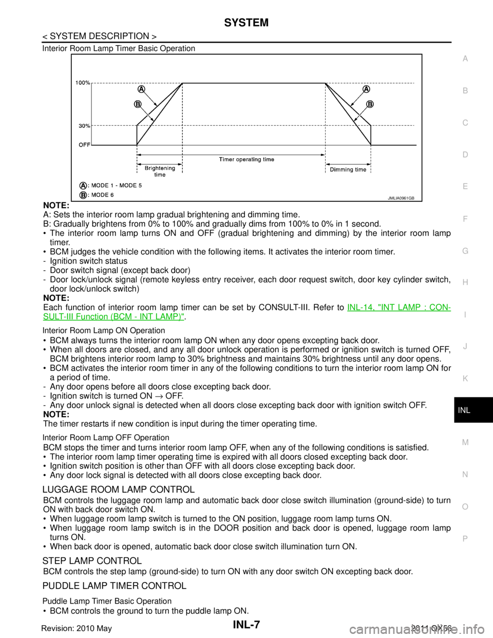
Interior Room Lamp Timer Basic Operation
NOTE:
A: Sets the interior room lamp gradual brightening and dimming time.
B: Gradually brightens from 0% to 100% and gradually dims from 100% to 0% in 1 second.
The interior room lamp turns ON and OFF (gradual brightening and dimming) by the interior room lamp
timer.
BCM judges the vehicle condition with the following items. It activates the interior room timer.
- Ignition switch status
- Door switch signal (except back door)
- Door lock/unlock signal (remote keyless entry receiv er, each door request switch, door key cylinder switch,
door lock/unlock switch)
NOTE:
Each function of interior room lamp ti mer can be set by CONSULT-III. Refer to INL-14, "
INT LAMP : CON-
SULT-III Function (BCM - INT LAMP)".
Interior Room Lamp ON Operation
BCM always turns the interior room lamp ON when any door opens excepting back door.
When all doors are closed, and any all door unlock operation is performed or ignition switch is turned OFF,
BCM brightens interior room lamp to 30% bri ghtness and maintains 30% brightness until any door opens.
BCM activates the interior room timer in any of the fo llowing conditions to turn the interior room lamp ON for
a period of time.
- Any door opens before all doors close excepting back door.
- Ignition switch is turned ON → OFF.
- Any door unlock signal is detected when all doors cl ose excepting back door with ignition switch OFF.
NOTE:
The timer restarts if new condition is input during the timer operating time.
Interior Room Lamp OFF Operation
BCM stops the timer and turns interior room lamp OF F, when any of the following conditions is satisfied.
The interior room lamp timer operating time is expired with all doors closed excepting back door.
Ignition switch position is other than O FF with all doors close excepting back door.
Any door lock signal is detected with all doors close excepting back door.
LUGGAGE ROOM LAMP CONTROL
BCM controls the luggage room lamp and automatic back door close switch illumination (ground-side) to turn
ON with back door switch ON.
When luggage room lamp switch is turned to the ON position, luggage room lamp turns ON.
When luggage room lamp switch is in the DOOR position and back door is opened, luggage room lamp turns ON.
When back door is opened, automatic back door close switch illumination turn ON.
STEP LAMP CONTROL
BCM controls the step lamp (ground-side) to turn ON with any door switch ON excepting back door.
PUDDLE LAMP TIMER CONTROL
Puddle Lamp Timer Basic Operation
BCM controls the ground to turn the puddle lamp ON.
JMLIA0961GB
Revision: 2010 May2011 QX56
Page 3275 of 5598

INL-8
< SYSTEM DESCRIPTION >
SYSTEM
The puddle lamp turns ON and OFF by the puddle lamp timer.
BCM judges the vehicle condition with the following items. It activates the puddle lamp timer.
- Ignition switch status
- Door switch signal (except back door)
- Door lock/unlock signal (remote keyless entry receiver, each door request switch)
- Driver side door lock status
Puddle Lamp ON Operation
BCM activates the puddle lamp timer in any of the following conditions to turn the puddle lamp ON for a period
of time.
Any door opens excepting back door.
Any door opens before all doors close excepting back door.
Ignition switch is turned ON → OFF.
Door unlock signal by remote keyless entry rece iver or each door request switch is detected.
Driver side door is locked*.
NOTE:
The timer restarts if new condition is input during the timer operating time.
Puddle Lamp OFF Operation
BCM stops the timer and turns puddle lamp OFF, when any of the following conditions are satisfied.
The puddle lamp timer operating time is expired.
The interior room lamp OFF conditions.
The interior room lamp timer operating time is expired.
PUSH-BUTTON IGNITION SWITCH ILLUMINATION CONTROL
Push-button Ignition Switch Illumination Basic Operation
BCM controls the ON/OFF status of push-button igni tion switch illumination according to vehicle status.
BCM provides the push-button ignition switch illumi nation control signal and the ground to turn the push-but-
ton ignition switch illumination ON.
BCM cuts the ground supply while each illumination (tai l lamp) is ON. BCM switches to the ground control
according to the meter illumination control function. Refer to MWI-16, "
METER ILLUMINATION CONTROL :
System Description".
Heart Beat Operation
BCM repeats brightening and dimming operation of push-button ignition switch illumination when any of the
following conditions are satisfied.
Welcome light function operates.
When ignition switch is OFF and any of the following conditions are satisfied.
- Driver side door changes from closed to open
- Driver side door changes from locked to unlocked
- Intelligent Key ID comparison is OK and driver side door changes from open to closed
- ID comparison by Intelligent Key transponder is OK
Illumination ON Operation
When ignition switch is not OFF or tail lamp turns ON, push-button ignition switch illumination turns ON.
Dimming Operation
When tail lamp turns OFF and ignition switch is turned OFF, push-button ignition switch illumination dims to
50% brightness.
Illumination OFF Operation
Push-button ignition switch illumination turns OFF when ignition switch turns OFF and tail lamp turns from ON
to OFF, while push-button ignition switch illumination is in ON status.
When push-button ignition switch illumination is at 50% brightness or in heartbeat status, and any of the fol-
lowing conditions are satisfied, push-butt on ignition switch illumination turns OFF.
15 seconds after start of heartbeat operation.
When welcome light function is not operating and any on the following conditions is satisfied.
- Driver side door is closed
- Driver side door is locked
- Intelligent Key ID comparison is NG
- Comparison of Intelligent Key ID by transponder is NG
INTERIOR ROOM LAMP BATTERY SAVER SYSTEM
Revision: 2010 May2011 QX56
Page 3277 of 5598
INL-10
< SYSTEM DESCRIPTION >
SYSTEM
Each function of interior room lamp battery saver can be set by CONSULT-III. Refer to INL-15, "BATTERY
SAVER : CONSULT-III Function (BCM - BATTERY SAVER)".
ILLUMINATION CONTROL SYSTEM
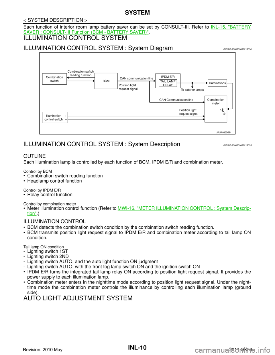
ILLUMINATION CONTROL SYSTEM : System DiagramINFOID:0000000006216054
ILLUMINATION CONTROL SYS TEM : System DescriptionINFOID:0000000006216055
OUTLINE
Each illumination lamp is controlled by each function of BCM, IPDM E/R and combination meter.
Control by BCM Combination switch reading function
Headlamp control function
Control by IPDM E/R Relay control function
Control by combination meter Meter illumination control function (Refer to MWI-16, "METER ILLUMINATION CONTROL : System Descrip-
tion".)
ILLUMINATION CONTROL
BCM detects the combination switch conditi on by the combination switch reading function.
BCM transmits position light request signal to IPDM E/R and combination meter according to tail lamp ON
condition.
Tail lamp ON condition- Lighting switch 1ST
- Lighting switch 2ND
- Lighting switch AUTO, and the auto light function ON judgment
- Lighting switch AUTO, with the front fog lamp switch ON and the ignition switch ON
IPDM E/R turns the integrated tail lamp relay ON acco rding to position light request signal. It provides the
power supply to each illumination lamp.
Combination meter enters in the nighttime mode accord ing to position light request signal. Under the night-
time mode the combination meter controls the illu minance by controlling each illumination lamp (ground
side).
AUTO LIGHT ADJUSTMENT SYSTEM
JPLIA0855GB
Revision: 2010 May2011 QX56
Page 3323 of 5598
INL-56
< DTC/CIRCUIT DIAGNOSIS >
INTERIOR ROOM LAMP POWER SUPPLY CIRCUIT
DTC/CIRCUIT DIAGNOSIS
INTERIOR ROOM LAMP PO WER SUPPLY CIRCUIT
DescriptionINFOID:0000000006216065
Provides the interior room lamp power supply. Also cu ts the power supply when the interior room lamp battery
saver activating.
Component Function CheckINFOID:0000000006216066
1.CHECK INTERIOR ROOM LAMP POWER SUPPLY FUNCTION
CONSULT-III ACTIVE TEST
1. Turn ignition switch ON.
2. Turn each interior room lamp ON.
- Personal lamp
- Map lamp
- Foot lamp
- Luggage room lamp
- Automatic back door close switch illumination
- Step lamp
- Puddle lamp
- Vanity mirror lamp
3. Select “BATTERY SAVER” of BCM (BATTERY SAVER) active test item.
4. With operating the test items, check t hat each interior room lamp turns ON/OFF.
Does the interior room lamp turn ON/OFF?
YES >> Interior room lamp power supply circuit is normal.
NO >> Refer to INL-56, "
Diagnosis Procedure".
Diagnosis ProcedureINFOID:0000000006216067
1.CHECK INTERIOR ROOM LAMP POWER SUPPLY OUTPUT
CONSULT-III ACTIVE TEST
1. Turn ignition switch OFF.
2. Disconnect the following connectors.
- Personal lamp
- Map lamp
- Foot lamp (both sides)
- Luggage room lamp
- Automatic back door close switch illumination
- Step lamp (ALL)
- Puddle lamp (both sides)
- Vanity mirror lamp (both sides)
3. Turn ignition switch ON.
4. Select “BATTERY SAVER” of BCM (BATTERY SAVER) active test item.
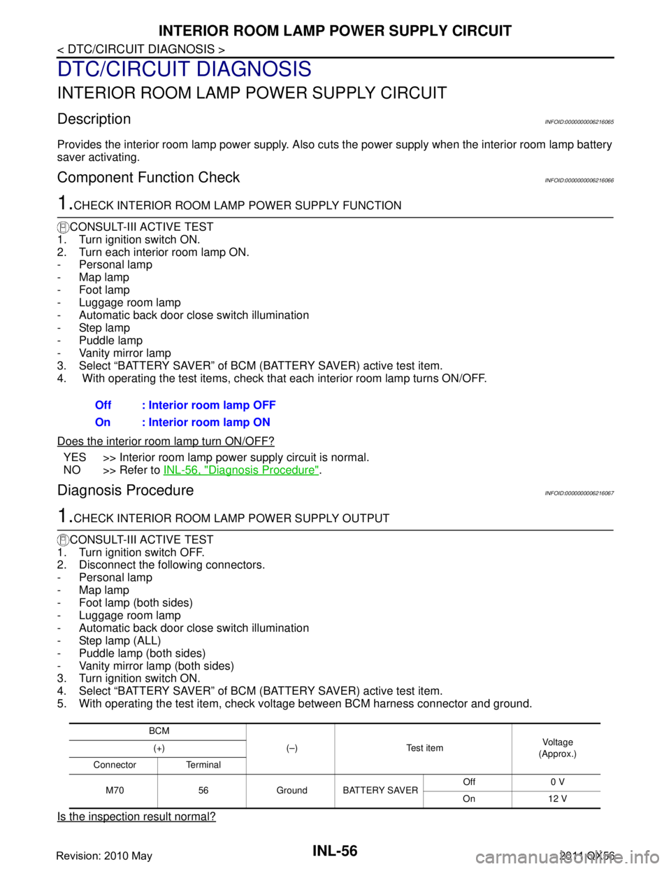
5. With operating the test item, check voltage between BCM harness connector and ground.
Is the inspection result normal?
Off : Interior room lamp OFF
On : Interior room lamp ON
BCM (–) Test item Vo l ta g e
(Approx.)
(+)
Connector Terminal
M70 56 Ground BATTERY SAVER Off 0 V
On 12 V
Revision: 2010 May2011 QX56
Page 3324 of 5598
INTERIOR ROOM LAMP POWER SUPPLY CIRCUIT
INL-57
< DTC/CIRCUIT DIAGNOSIS >
C
D E
F
G H
I
J
K
M A
B
INL
N
O P
YES >> GO TO 2.
NO >> GO TO 3.
2.CHECK INTERIOR ROOM LAMP POWER SUPPLY OPEN CIRCUIT
1. Turn ignition switch OFF.
2. Disconnect the BCM connector.
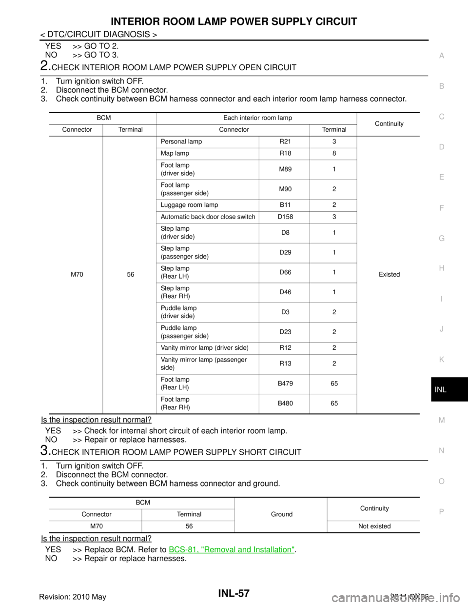
3. Check continuity between BCM harness connector and each interior room lamp harness connector.
Is the inspection result normal?
YES >> Check for internal short circuit of each interior room lamp.
NO >> Repair or replace harnesses.
3.CHECK INTERIOR ROOM LAMP POWER SUPPLY SHORT CIRCUIT
1. Turn ignition switch OFF.
2. Disconnect the BCM connector.
3. Check continuity between BCM harness connector and ground.
Is the inspection result normal?
YES >> Replace BCM. Refer to BCS-81, "Removal and Installation".
NO >> Repair or replace harnesses.
BCM Each interior room lamp Continuity
Connector Terminal Connector Terminal
M70 56 Personal lamp R21 3
Existed
Map lamp R18 8
Foot lamp
(driver side)
M89 1
Foot lamp
(passenger side) M90 2
Luggage room lamp B11 2
Automatic back door close switch D158 3
Ste p l am p
(driver side) D8 1
Ste p l am p
(passenger side) D29 1
Ste p l am p
(Rear LH) D66 1
Ste p l am p
(Rear RH) D46 1
Puddle lamp
(driver side) D3 2
Puddle lamp
(passenger side) D23 2
Vanity mirror lamp (driver side) R12 2
Vanity mirror la mp (passenger
side) R13 2
Foot lamp
(Rear LH) B479 65
Foot lamp
(Rear RH) B480 65
BCM
GroundContinuity
Connector Terminal
M70 56 Not existed
Revision: 2010 May2011 QX56
Page 3325 of 5598

INL-58
< DTC/CIRCUIT DIAGNOSIS >
INTERIOR ROOM LAMP CONTROL CIRCUIT
INTERIOR ROOM LAMP CONTROL CIRCUIT
DescriptionINFOID:0000000006216068
Controls each interior room lamp (ground side) by PWM signal.
NOTE:
PWM signal control period is approximately 250 Hz (in the gradual brightening/dimming).
Component Function CheckINFOID:0000000006216069
CAUTION:
Before performing the diagnosis, check that the following are normal.
Interior room lamp power supply
Map lamp bulb
Personal lamp bulb
Foot lamp bulb
1.CHECK INTERIOR ROOM LAMP CONTROL FUNCTION
CONSULT-III ACTIVE TEST
1. Switch the map lamp switch and personal lamp switch to DOOR.
2. Turn ignition switch ON.
3. Select “INT LAMP” of BCM (INT LAMP) active test item.
4. With operating the test items, c heck that each interior room lamp turns ON/OFF (gradual brightening/dim-
ming).
Does the interior room lamp turns ON/OFF (gradual brightening/dimming)?
YES >> Interior room lamp control circuit is normal.
NO >> Refer to INL-58, "
Diagnosis Procedure".
Diagnosis ProcedureINFOID:0000000006216070
1.CHECK INTERIOR ROOM LAMP CONTROL OUTPUT
CONSULT-III ACTIVE TEST
1. Switch the map lamp switch and personal lamp switch to DOOR.
2. Turn ignition switch OFF.
3. Remove all the bulbs of map lamp, foot lamp and personal lamp.
4. Turn ignition switch ON.
5. Select “INT LAMP” of BCM (INT LAMP) active test item.
6. With operating the test item, check c ontinuity between BCM harness connector and ground.
Is the inspection result normal?
YES >> GO TO 2.
Fixed ON>>GO TO 3.
Fixed OFF>>Replace BCM. Refer to BCS-81, "
Removal and Installation".
2.CHECK INTERIOR ROOM LAMP CONTROL OPEN CIRCUIT
1. Turn ignition switch OFF.
2. Disconnect BCM connector, map lamp connector, personal lamp connector and foot lamp connector.
3. Check continuity between BCM harness connector and foot lamp harness connector.
On : Interior room lamp gradual brightening
Off : Interior room lamp gradual dimming
BCM
Ground Test item Continuity
Connector Terminal
M70 63 INT LAMP On Existed
Off Not existed
Revision: 2010 May2011 QX56
Page 3326 of 5598
INTERIOR ROOM LAMP CONTROL CIRCUITINL-59
< DTC/CIRCUIT DIAGNOSIS >
C
DE
F
G H
I
J
K
M A
B
INL
N
O P
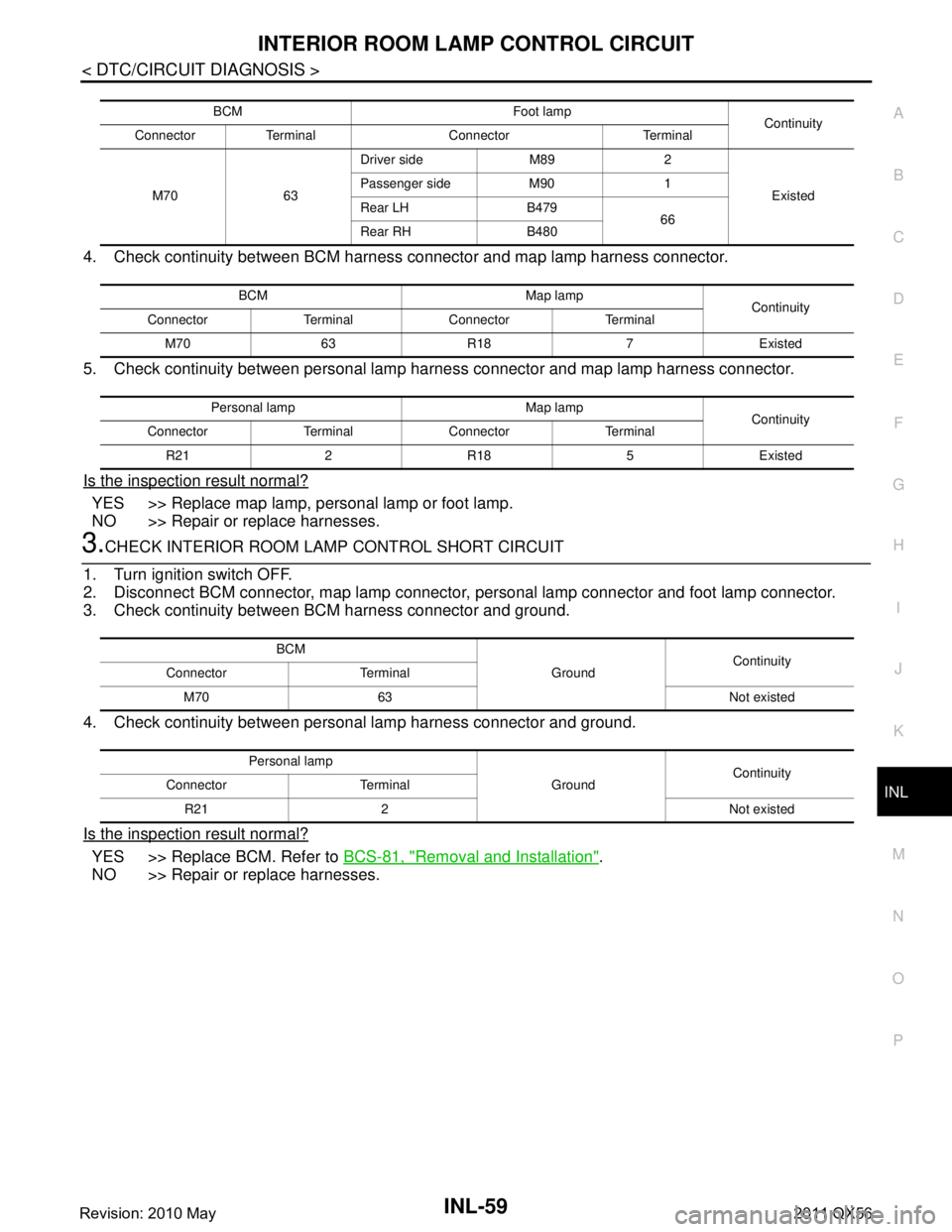
4. Check continuity between BCM harness connector and map lamp harness connector.
5. Check continuity between personal lamp harness connector and map lamp harness connector.
Is the inspection result normal?
YES >> Replace map lamp, personal lamp or foot lamp.
NO >> Repair or replace harnesses.
3.CHECK INTERIOR ROOM LAMP CONTROL SHORT CIRCUIT
1. Turn ignition switch OFF.
2. Disconnect BCM connector, map lamp connector, personal lamp connector and foot lamp connector.
3. Check continuity between BCM harness connector and ground.
4. Check continuity between personal lamp harness connector and ground.
Is the inspection result normal?
YES >> Replace BCM. Refer to BCS-81, "Removal and Installation".
NO >> Repair or replace harnesses.
BCM Foot lamp Continuity
Connector Terminal Connector Terminal
M70 63 Driver side M89 2
Existed
Passenger side M90 1
Rear LH B479
66
Rear RH B480
BCM Map lamp Continuity
Connector Terminal Connector Terminal
M70 63 R18 7 Existed
Personal lamp Map lamp Continuity
Connector Terminal Connector Terminal
R212R185Existed
BCM GroundContinuity
Connector Terminal
M70 63 Not existed
Personal lamp GroundContinuity
Connector Terminal
R21 2 Not existed
Revision: 2010 May2011 QX56
Page 3327 of 5598
INL-60
< DTC/CIRCUIT DIAGNOSIS >
LUGGAGE ROOM LAMP CIRCUIT
LUGGAGE ROOM LAMP CIRCUIT
DescriptionINFOID:0000000006216071
Controls the luggage room lamp and automatic back door close switch illumination (ground side) to turn the
luggage room lamp and automatic back door close switch illumination ON and OFF.
Diagnosis ProcedureINFOID:0000000006216072
CAUTION:
Before performing the diagnosis, check that the following are normal.
Interior room lamp power supply
Luggage room lamp bulb
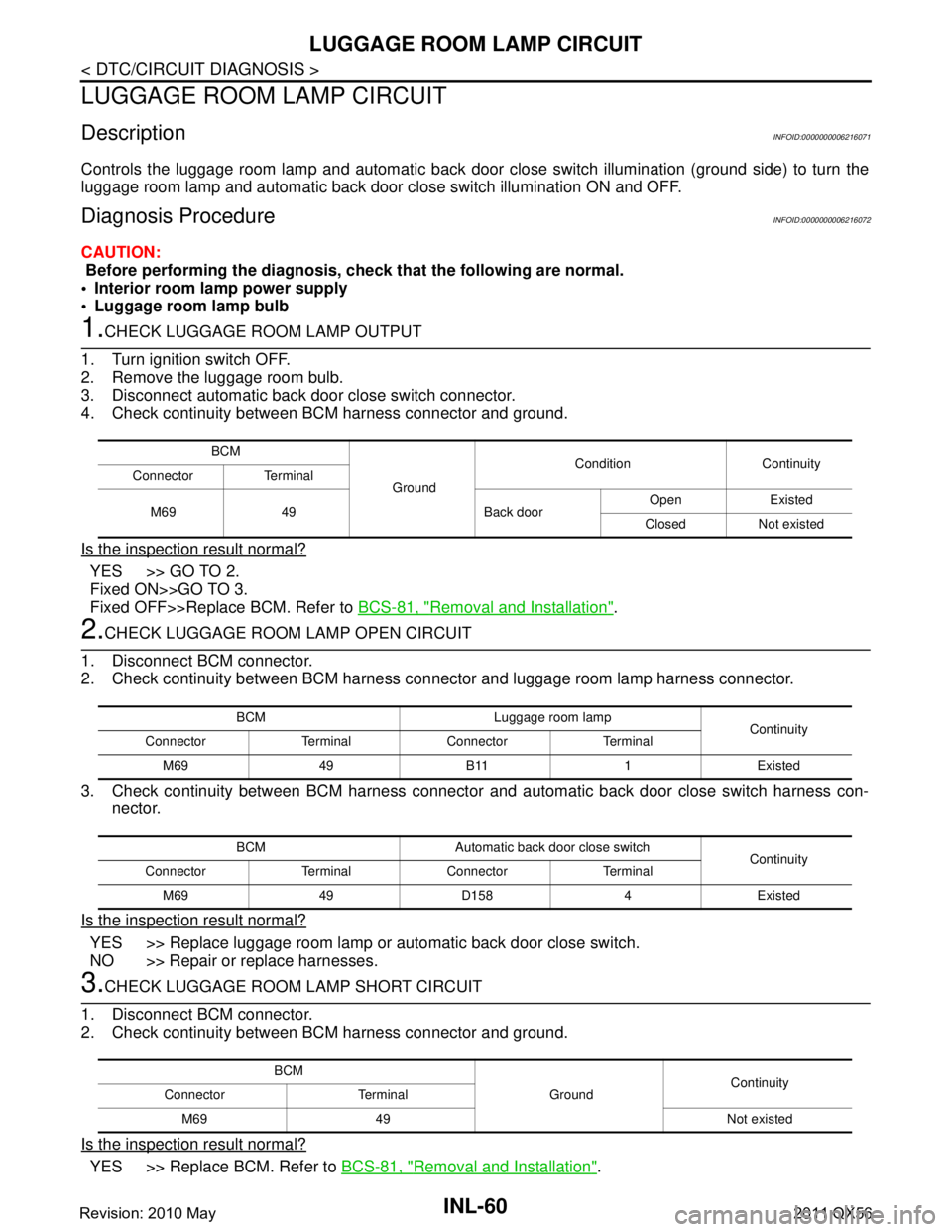
1.CHECK LUGGAGE ROOM LAMP OUTPUT
1. Turn ignition switch OFF.
2. Remove the luggage room bulb.
3. Disconnect automatic back door close switch connector.
4. Check continuity between BCM harness connector and ground.
Is the inspection result normal?
YES >> GO TO 2.
Fixed ON>>GO TO 3.
Fixed OFF>>Replace BCM. Refer to BCS-81, "
Removal and Installation".
2.CHECK LUGGAGE ROOM LAMP OPEN CIRCUIT
1. Disconnect BCM connector.
2. Check continuity between BCM harness c onnector and luggage room lamp harness connector.
3. Check continuity between BCM harness connector and automatic back door close switch harness con-
nector.
Is the inspection result normal?
YES >> Replace luggage room lamp or automatic back door close switch.
NO >> Repair or replace harnesses.
3.CHECK LUGGAGE ROOM LAMP SHORT CIRCUIT
1. Disconnect BCM connector.
2. Check continuity between BCM harness connector and ground.
Is the inspection result normal?
YES >> Replace BCM. Refer to BCS-81, "Removal and Installation".
BCM
Ground Condition Continuity
Connector Terminal
M69 49 Back door Open Existed
Closed Not existed
BCM Luggage room lamp Continuity
Connector Terminal Connector Terminal
M69 49 B11 1 Existed
BCM Automatic back door close switch Continuity
Connector Terminal Connector Terminal
M69 49 D158 4 Existed
BCM GroundContinuity
Connector Terminal
M69 49 Not existed
Revision: 2010 May2011 QX56