2011 INFINITI QX56 warning light
[x] Cancel search: warning lightPage 3847 of 5598
![INFINITI QX56 2011 Factory Service Manual
PCS-6
< SYSTEM DESCRIPTION >[IPDM E/R]
SYSTEM
NOTE:
BCM controls the starter relay.
RELAY CONTROL SYSTEM : Fail-SafeINFOID:0000000006220163
CAN COMMUNICATION CONTROL
When CAN communication with ECM a INFINITI QX56 2011 Factory Service Manual
PCS-6
< SYSTEM DESCRIPTION >[IPDM E/R]
SYSTEM
NOTE:
BCM controls the starter relay.
RELAY CONTROL SYSTEM : Fail-SafeINFOID:0000000006220163
CAN COMMUNICATION CONTROL
When CAN communication with ECM a](/manual-img/42/57033/w960_57033-3846.png)
PCS-6
< SYSTEM DESCRIPTION >[IPDM E/R]
SYSTEM
NOTE:
BCM controls the starter relay.
RELAY CONTROL SYSTEM : Fail-SafeINFOID:0000000006220163
CAN COMMUNICATION CONTROL
When CAN communication with ECM and BCM is impossible,
IPDM E/R performs fail-safe control. After CAN
communication recovers normally, it also returns to normal control.
If No CAN Communication Is Available With ECM
If No CAN Communication Is Available With BCM
Control relay Input/output Transmi t unit Control part Reference page
Headlamp low relay
Headlamp high relay Low beam request signal
High beam request signal
BCM (CAN)
Headlamp (LO)
Headlamp (HI) EXL-10
Front fog lamp relay Front fog light request signal BCM (CAN) Front fog lamp
EXL-20
Tail lamp relay Position light request signal BCM (CAN) Parking lamp
License plate
lamp
Tail lamp
Side marker lamp EXL-18
Illuminations
INL-6
Front wiper relay
Front wiper high relayFront wiper request signal BCM (CAN)
Front wiper motorWW-7Front wiper stop position sig-
nal Front wiper motor
Rear window defogger
relay Rear window defogger control
signal
BCM (CAN)
Rear window defog-
ger
DEF-6
Horn relay
Theft warning horn
relay Theft warning horn request
signal
Horn reminder signal BCM (CAN)
Horn (high)
Horn (low) SEC-17
Starter relayNOTE
Starter control relayStarter control rela
y signal BCM (CAN)
Starter motorSEC-10
,
SEC-10Steering lock unit condition
signal Steering lock unit
Starter relay control signal TCM
Steering lock relay Steering lock relay signal BCM (CAN)
Steering lock unitSEC-10
Steering lock unit condition
signal Steering lock unit
A/T shift selector (detention
switch) signal A/T shift selector
(detention switch)
A/C relay A/C compressor request sig-
nal ECM (CAN)
A/C compressor
(Magnet clutch) HAC-17
Headlamp washer relay
Headlamp washer request
signal BCM (CAN)Headlamp washer
pump WW-13
Ignition relay
Ignition relay-2
Ignition relay-3Ignition switch ON signal BCM (CAN)
Each control unit,
sensor, actuator and
relay (ignition power
supply)PCS-29Vehicle speed signal
Combination meter
(CAN)
Push-button ignition switch
signal Push-button ignition
switch
Control part Fail-safe operation
Cooling fan Transmits the pulse duty signal (PWM signal) 100% when the ignition switch is turned ON.
Transmits the pulse duty signal (PWM signal) 0% when the ignition switch is turned OFF.
A/C compressor A/C relay OFF
Alternator Transmits the power generation command signal (PWM signal) 0%
Revision: 2010 May2011 QX56
Page 3853 of 5598
![INFINITI QX56 2011 Factory Service Manual
PCS-12
< SYSTEM DESCRIPTION >[IPDM E/R]
DIAGNOSIS SYSTEM (IPDM E/R)
CONSULT-III Function (IPDM E/R)
INFOID:0000000006220171
APPLICATION ITEM
CONSULT-III performs the following functions via CAN commu INFINITI QX56 2011 Factory Service Manual
PCS-12
< SYSTEM DESCRIPTION >[IPDM E/R]
DIAGNOSIS SYSTEM (IPDM E/R)
CONSULT-III Function (IPDM E/R)
INFOID:0000000006220171
APPLICATION ITEM
CONSULT-III performs the following functions via CAN commu](/manual-img/42/57033/w960_57033-3852.png)
PCS-12
< SYSTEM DESCRIPTION >[IPDM E/R]
DIAGNOSIS SYSTEM (IPDM E/R)
CONSULT-III Function (IPDM E/R)
INFOID:0000000006220171
APPLICATION ITEM
CONSULT-III performs the following functions via CAN communication with IPDM E/R.
SELF DIAGNOSTIC RESULT
Refer to PCS-22, "DTCIndex".
DATA MONITOR
Monitor item
Oil pressure warning lamp does not operate Perform auto active test.
Does the oil pressure warning
lamp blink?YES
Harness or connector be-
tween IPDM E/R and oil
pressure switch
Oil pressure switch
IPDM E/R
NO CAN communication signal
between IPDM E/R and
BCM
CAN communication signal
between BCM and combi-
nation meter
Combination meter
Symptom Inspection contents Possible cause
Diagnosis mode Description
Ecu Identification Allows confirmation of IPDM E/R part number.
Self Diagnostic Result Displays the diagnosis results judged by IPDM E/R.
Data Monitor Displays the real-time input/output data from IPDM E/R input/output data.
Active Test IPDM E/R can provide a drive signal to electronic components to check their operations.
CAN Diag Support Monitor The results of transmit/receive diagnosis of CAN communication can be read.
Monitor Item [Unit] MAIN SIG-
NALS Description
RAD FAN REQ
[1/2/3/4] ×Displays the value of the cooling fan speed request signal received from ECM via
CAN communication.
AC COMP REQ
[Off/On] ×Displays the status of the A/C compressor request signal received from ECM via
CAN communication.
TA I L & C L R R E Q
[Off/On] ×
Displays the status of the position light request signal received from BCM via CAN
communication.
HL LO REQ
[Off/On] ×Displays the status of the low beam request signal received from BCM via CAN
communication.
HL HI REQ
[Off/On] ×Displays the status of the high beam request signal received from BCM via CAN
communication.
FR FOG REQ
[Off/On] ×Displays the status of the front fog light request signal received from BCM via
CAN communication.
FR WIP REQ
[Stop/1LOW/Low/Hi] ×
Displays the status of the front wiper request signal received from BCM via CAN
communication.
WIP AUTO STOP
[STOP P/ACT P] ×
Displays the status of the front wiper auto stop signal judged by IPDM E/R.
WIP PROT
[Off/BLOCK] ×
Displays the status of the front wiper fail-safe operation judged by IPDM E/R.
IGN RLY1 -REQ
[Off/On] Displays the status of the ignition switch ON signal received from BCM via CAN
communication.
IGN RLY
[Off/On] ×
Displays the status of the ignition relay judged by IPDM E/R.
Revision: 2010 May2011 QX56
Page 4295 of 5598

SB-20
< REMOVAL AND INSTALLATION >
THIRD SEAT BELT
4. Remove the rear kicking plate inner. Refer to INT-20, "KICKING PLATE INNER : Removal and Installa-
tion".
5. Remove the luggage side lower finisher (LH/RH). Refer to INT-36, "
LUGGAGE SIDE LOWER FINISHER :
Removal and Installation".
6. Remove the roof garnish. Refer to INT-29, "
Removal and Installation".
7. Remove the back pillar garnish (LH/RH). Refer to INT-37, "
BACK PILLAR GARNISH : Removal and
Installation".
8. Remove the shoulder anchor mounting anchor bolt and then remove the shoulder anchor.
9. Remove the seat belt retractor mounting anchor bolt and then remove the third seat belt retractor.
THIRD SEAT BELT CENTER RETRACTOR
1. Remove the roof garnish. Refer to INT-29, "Removal and Installation".
2. Remove headlining assembly rear clips. Refer to INT-29, "
Removal and Installation".
3. Slightly lower the headlining assembly rear and secure work space.
4. Remove the seat belt guide plate anchor bolt.
5. Remove the center seat belt retractor mounting anchor bolt and screw and then remove the center seat
belt retractor.
INSTALLATION
Install in the reverse order of removal.
SEAT BELT BUCKLE
SEAT BELT BUCKLE : InspectionINFOID:0000000006217630
AFTER A COLLISION
WARNING:
Inspect all seat belt assemblies in cluding retractors and attached hardware after any collision.
NISSAN/INFINITI recommends that all seat belt assemblies in use during a collision be replaced
unless the collision was minor and th e belts show no damage and continue to operate properly. Fail-
ure to do so could result in seri ous personal injury in an accident. Seat belt assemblies not in use dur-
ing a collision should also be re placed if either damage or improper operation was noted. Seat belt
pre-tensioners should be replaced even if the seat be lts were not in use during a frontal collision in
which the air bags were deployed.
Replace any seat belt assembly (including anchor bolts) if:
The seat belt is in use at the time of a collision (e xcept for minor collisions and the belts, retractors and buck-
les show no damage and continue to operate properly).
The seat belt is damaged in an accident. (i.e. to rn webbing, bent retractor or guide, etc.)
The seat belt attaching point is damaged in an accident . Inspect the seat belt attaching area for damage or
distortion and repair if necessary before installing a new seat belt assembly.
Anchor bolts are deformed or worn out.
The seat belt pre-tensioner must be replaced even if t he seat belts were not in use during the collision in
which the air bags are deployed.
PRELIMINARY CHECKS
1. Check that the seat belt retractor, s eat belt anchor and buckle bolts are tightened firmly.
2. Repeat step above if necessary to check the other seat belts.
Revision: 2010 May2011 QX56
Page 5405 of 5598

WCS
WCS-1
DRIVER INFORMATION & MULTIMEDIA
C
DE
F
G H
I
J
K L
M B
SECTION WCS
A
O P
CONTENTS
WARNING CHIME SYSTEM
PRECAUTION ................ ...............................3
PRECAUTIONS .............................................. .....3
Precaution for Supplemental Restraint System
(SRS) "AIR BAG" and "SEAT BELT PRE-TEN-
SIONER" ............................................................. ......
3
SYSTEM DESCRIPTION ..............................4
COMPONENT PARTS ................................... .....4
Component Parts Location .................................. ......4
Component Description .............................................4
Combination Meter ....................................................5
SYSTEM ..............................................................6
WARNING CHIME SYSTEM .......................................6
WARNING CHIME SYSTEM : System Diagram . ......6
WARNING CHIME SYSTEM : System Description
......
6
WARNING CHIME SYSTEM : Fail-Safe ...................7
LIGHT REMINDER WARNING CHIME ................. ......8
LIGHT REMINDER WARNING CHIME : System
Diagram .....................................................................
8
LIGHT REMINDER WARNING CHIME : System
Description ................................................................
8
FRONT FOG LIGHT REMINDER WARNING
CHIME .................................................................... ......
9
FRONT FOG LIGHT REMINDER WARNING
CHIME : System Diagram .......................................
10
FRONT FOG LIGHT REMINDER WARNING
CHIME : System Description ...................................
10
SEAT BELT WARNING CHIME ............................ ....10
SEAT BELT WARNING CHIME : System Diagram
....
11
SEAT BELT WARNING CHIME : System Descrip-
tion ...................................................................... ....
11
PARKING BRAKE RELEASE WARNING CHIME ....12
PARKING BRAKE RELEASE WARNING CHIME
: System Diagram ................................................ ....
12
PARKING BRAKE RELEASE WARNING CHIME
: System Description ................................................
12
DIAGNOSIS SYSTEM (COMBINATION
METER) .............................................................
14
CONSULT-III Function ............................................14
DIAGNOSIS SYSTEM (BCM) ...........................19
COMMON ITEM ..................................................... ....19
COMMON ITEM : CONSULT-III Function (BCM -
COMMON ITEM) .....................................................
19
BUZZER ................................................................. ....20
BUZZER : CONSULT-III Function (BCM - BUZZ-
ER) ..........................................................................
20
ECU DIAGNOSIS INFORMATION ..............22
COMBINATION METER ...................................22
Reference Value .................................................. ....22
Fail-Safe ..................................................................29
DTC Index ...............................................................30
BCM (BODY CONTROL MODULE) .................31
List of ECU Reference .............................................31
WIRING DIAGRAM ......................................32
WARNING CHIME SYSTEM .............................32
Wiring Diagram .................................................... ....32
BASIC INSPECTION ...................................37
DIAGNOSIS AND REPAIR WORKFLOW ........37
Work Flow ............................................................ ....37
DTC/CIRCUIT DIAGNOSIS .........................39
POWER SUPPLY AND GROUND CIRCUIT ....39
COMBINATION METER ........................................ ....39
Revision: 2010 May2011 QX56
Page 5406 of 5598

WCS-2
COMBINATION METER : Diagnosis Procedure ....39
METER BUZZER CIRCUIT ................................40
Component Function Check ................................ ...40
Diagnosis Procedure .............................................40
SEAT BELT BUCKLE SWITCH SIGNAL CIR-
CUIT ...................................................................
41
Component Function Check .............................. ...41
Diagnosis Procedure .............................................41
Component Inspection ............................................42
PARKING BRAKE SWITCH SIGNAL CIR-
CUIT ...................................................................
43
Diagnosis Procedure ........................................... ...43
Component Inspection ............................................43
SYMPTOM DIAGNOSIS ............................44
THE LIGHT REMINDER WARNING DOES
NOT SOUND ................................................... ...
44
Description ........................................................... ...44
Diagnosis Procedure ...............................................44
THE SEAT BELT WARNING CONTINUES
SOUNDING, OR DOES NOT SOUND ...............
45
Description ........................................................... ...45
Diagnosis Procedure ...............................................45
THE PARKING BRAKE RELEASE WARNING
CONTINUES SOUNDING, OR DOES NOT
SOUND ..............................................................
46
Description ........................................................... ...46
Diagnosis Procedure ...............................................46
Revision: 2010 May2011 QX56
Page 5410 of 5598

WCS-6
< SYSTEM DESCRIPTION >
SYSTEM
SYSTEM
WARNING CHIME SYSTEM
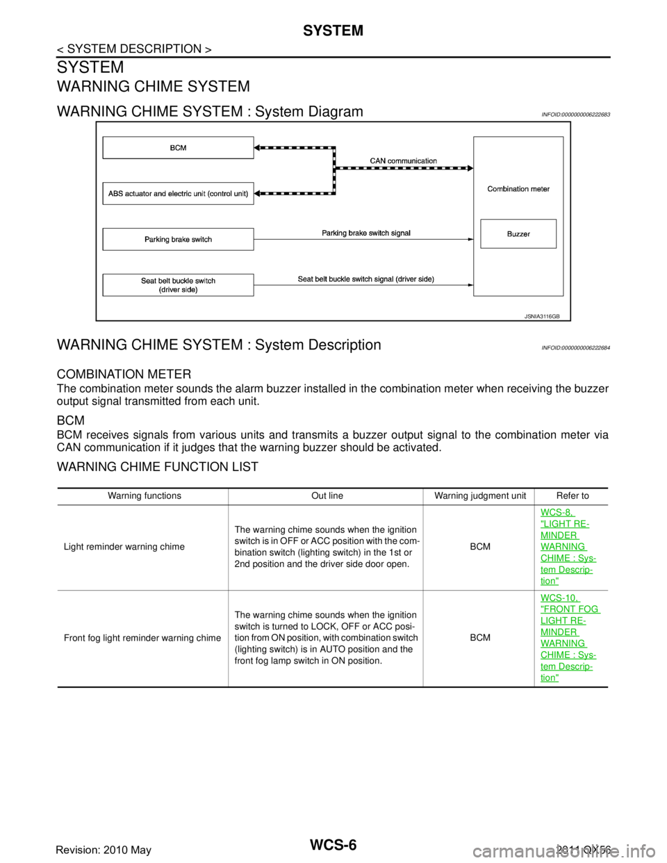
WARNING CHIME SYSTEM : System DiagramINFOID:0000000006222683
WARNING CHIME SYSTEM : System DescriptionINFOID:0000000006222684
COMBINATION METER
The combination meter sounds the alarm buzzer install ed in the combination meter when receiving the buzzer
output signal transmitted from each unit.
BCM
BCM receives signals from various units and transmits a buzzer output signal to the combination meter via
CAN communication if it judges that the warning buzzer should be activated.
WARNING CHIME FUNCTION LIST
JSNIA3116GB
Warning functions Out line Warning judgment unit Refer to
Light reminder warning chime The warning chime sounds when the ignition
s w i t c h i s i n O F F o r A C C p o s i t i o n w i t h t h e c o m -
bination switch (lighting switch) in the 1st or
2nd position and the driver side door open. BCMWCS-8,
"LIGHT RE-
MINDER
WARNING
CHIME : Sys-
tem Descrip-
tion"
Front fog light reminder warning chime
The warning chime sounds when the ignition
switch is turned to LOCK, OFF or ACC posi-
tion from ON position, with combination switch
(lighting switch) is in AUTO position and the
front fog lamp switch in ON position. BCMWCS-10,
"FRONT FOG
LIGHT RE-
MINDER
WARNING
CHIME : Sys-
tem Descrip-
tion"
Revision: 2010 May2011 QX56
Page 5412 of 5598

WCS-8
< SYSTEM DESCRIPTION >
SYSTEM
LIGHT REMINDER WARNING CHIME
LIGHT REMINDER WARNING CHIME : System DiagramINFOID:0000000006222543
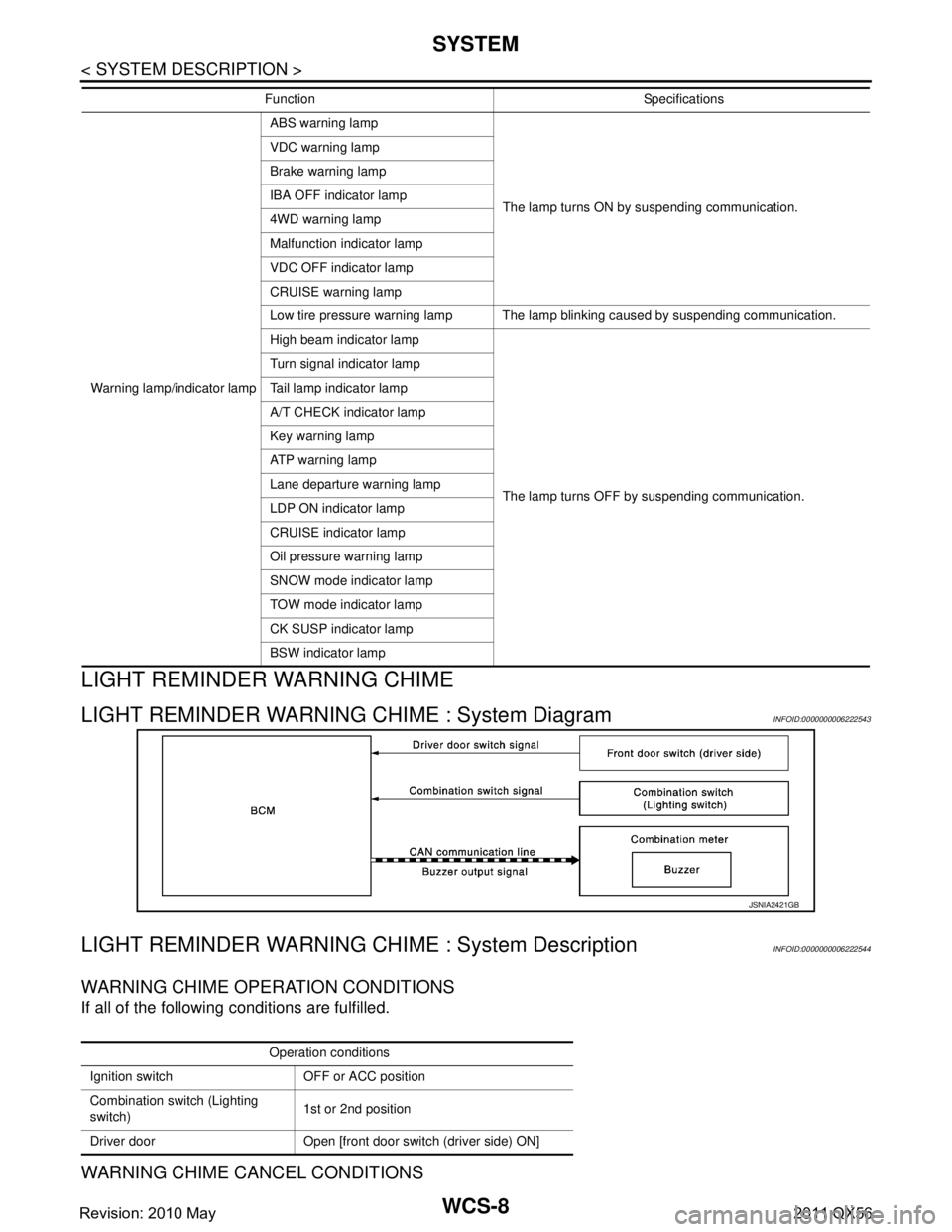
LIGHT REMINDER WARNING CHIME : System DescriptionINFOID:0000000006222544
WARNING CHIME OPERATION CONDITIONS
If all of the following conditions are fulfilled.
WARNING CHIME CANCEL CONDITIONS
Warning lamp/indicator lampABS warning lamp
The lamp turns ON by suspending communication.
VDC warning lamp
Brake warning lamp
IBA OFF indicator lamp
4WD warning lamp
Malfunction indicator lamp
VDC OFF indicator lamp
CRUISE warning lamp
Low tire pressure warning lamp The lamp blinking caused by suspending communication.
High beam indicator lamp
The lamp turns OFF by suspending communication.
Turn signal indicator lamp
Tail lamp indicator lamp
A/T CHECK indicator lamp
Key warning lamp
ATP warning lamp
Lane departure warning lamp
LDP ON indicator lamp
CRUISE indicator lamp
Oil pressure warning lamp
SNOW mode indicator lamp
TOW mode indicator lamp
CK SUSP indicator lamp
BSW indicator lamp
Function Specifications
JSNIA2421GB
Operation conditions
Ignition switch OFF or ACC position
Combination switch (Lighting
switch) 1st or 2nd position
Driver door Open [front door switch (driver side) ON]
Revision: 2010 May2011 QX56
Page 5413 of 5598

WCS
SYSTEMWCS-9
< SYSTEM DESCRIPTION >
C
DE
F
G H
I
J
K L
M B A
O P
Warning is canceled if any of t he following conditions is fulfilled.
SIGNAL PATH
1. BCM requires warning chime output to combination meter when it judges light reminder warning chime is
necessary from signals below.
2. Combination meter sounds integrated buzzer, followi ng the warning chime output requirement (below sig-
nal) from BCM.
TIMING CHART
FRONT FOG LIGHT REMINDER WARNING CHIME
Operation conditions
Ignition switch ON
Combination switch (Lighting
switch) OFF or AUTO position
Driver door Close [front door switch (driver side) OFF]
Signal name Signal path
Ignition switch signal —
Combination switch signal Combination switch (Lighting switch) BCM
Driver door switch signal Front door switch (driver side) BCM
Signal name Signal path
Buzzer output signal BCM Combination meter
JSNIA2426GB
Revision: 2010 May2011 QX56