Page 3782 of 5598

MWI
COMBINATION METERMWI-39
< ECU DIAGNOSIS INFORMATION >
C
DE
F
G H
I
J
K L
M B A
O P
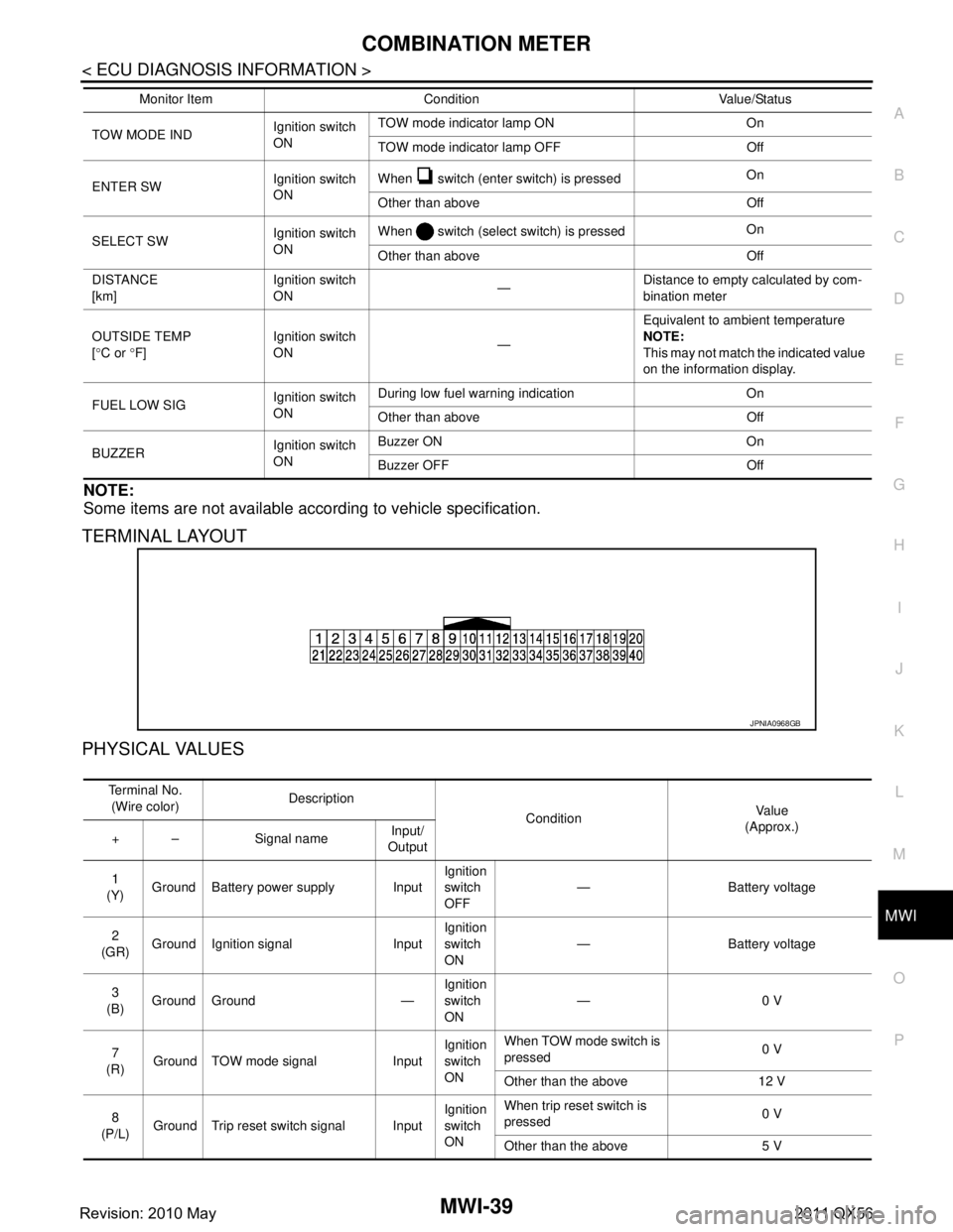
NOTE:
Some items are not available according to vehicle specification.
TERMINAL LAYOUT
PHYSICAL VALUES
TOW MODE IND Ignition switch
ONTOW mode indicator lamp ON On
TOW mode indicator lamp OFF Off
ENTER SW Ignition switch
ONWhen switch (enter switch) is pressed
On
Other than above Off
SELECT SW Ignition switch
ONWhen switch (select switch) is pressed
On
Other than above Off
DISTANCE
[km] Ignition switch
ON
—Distance to empty calculated by com-
bination meter
OUTSIDE TEMP
[ ° C or °F] Ignition switch
ON
—Equivalent to ambient temperature
NOTE:
This may not match the indicated value
on the information display.
FUEL LOW SIG Ignition switch
ONDuring low fuel warning indication On
Other than above Off
BUZZER Ignition switch
ONBuzzer ON On
Buzzer OFF Off
Monitor Item Condition Value/Status
JPNIA0968GB
Te r m i n a l N o .
(Wire color) Description
ConditionVa l u e
(Approx.)
+ – Signal name Input/
Output
1
(Y) Ground Battery power supply Input Ignition
switch
OFF— Battery voltage
2
(GR) Ground Ignition signal Input Ignition
switch
ON
— Battery voltage
3
(B) Ground Ground — Ignition
switch
ON—0 V
7
(R) Ground TOW mode signal Input Ignition
switch
ONWhen TOW mode switch is
pressed
0 V
Other than the above 12 V
8
(P/L) Ground Trip reset switch signal Input Ignition
switch
ONWhen trip reset switch is
pressed
0 V
Other than the above 5 V
Revision: 2010 May2011 QX56
Page 3785 of 5598

MWI-42
< ECU DIAGNOSIS INFORMATION >
COMBINATION METER
Fail-Safe
INFOID:0000000006221722
FA I L - S A F E
The combination meter activates the fail-safe contro l if CAN communication with each unit is malfunctioning.
37
(R/Y) Ground Non-manual mode signal Input Ignition
switch
ONSelector manual mode po-
sition
12 V
Other than the above 0 V
38
(L/W) Ground Manual mode shift down
signal InputIgnition
switch
ON Selector lever DOWN oper-
ation
0 V
Other than the above 12 V
39
(Y/B) Ground Manual mode shift up sig-
nal InputIgnition
switch
ON Selector lever UP operation 0 V
Other than the above 12 V
40
(G/W) Ground Manual mode signal Input Ignition
switch
ONSelector manual mode po-
sition
0 V
Other than the above 12 V
Te r m i n a l N o .
(Wire color) Description
ConditionVa l u e
(Approx.)
+ – Signal name Input/
Output
Function Specifications
Speedometer
Reset to zero by suspending communication.
Tachometer
Engine coolant temperature gauge
Engine oil pressure gauge
Illumination control When suspending communication, changes to nighttime mode.
Information display Odo/trip meter An indicated value is maintained at communications blackout.
Shift position indicator The display turns OFF by suspending communication.
Door open warning The display turns OFF by suspending communication.
Buzzer The buzzer turns OFF by suspending communication.
Revision: 2010 May2011 QX56
Page 3786 of 5598

MWI
COMBINATION METERMWI-43
< ECU DIAGNOSIS INFORMATION >
C
DE
F
G H
I
J
K L
M B A
O P
DTC IndexINFOID:0000000006221723
Warning lamp/indicator lamp ABS warning lamp
The lamp turns ON by suspending communication.
VDC warning lamp
Brake warning lamp
IBA OFF indicator lamp
4WD warning lamp
Malfunction indicator lamp
VDC OFF indicator lamp
CRUISE warning lamp
Low tire pressure warning lamp The lamp blinking caused by suspending communication.
High beam indicator lamp
The lamp turns OFF by suspending communication.
Turn signal indicator lamp
Tail lamp indicator lamp
A/T CHECK indicator lamp
Key warning lamp
AT P w a r n i n g l a m p
Lane departure warning lamp
LDP ON indicator lamp
CRUISE indicator lamp
Oil pressure warning lamp
SNOW mode indicator lamp
TOW mode indicator lamp
CK SUSP indicator lamp
BSW indicator lamp
Function Specifications
Display contents of CONSULT-III Diagnostic item is detected when... Refer to
CAN COMM CIRCUIT
[U1000] When combination meter is not transmitting or receiving CAN communication signal
for 2 seconds or more. MWI-59,
"Diagnosis
Procedure"
CONTROL UNIT (CAN)
[U1010]
When detecting error during the initial diagnosis of the CAN controller of combina-
tion meter. MWI-60, "Diagnosis
Procedure"
VEHICLE SPEED
[B2205]
The abnormal vehicle speed signal is input from the ABS actuator and electric unit
(control unit) for
2 seconds or more. MWI-61, "Diagnosis
Procedure"
ENGINE SPEED
[B2267]
If ECM continuously transmits abnormal engine speed signals for 2 seconds or
more. MWI-62, "Diagnosis
Procedure"
WATER TEMP
[B2268]
If ECM continuously transmits abnormal engine coolant temperature signals for 60
seconds or more. MWI-63, "Diagnosis
Procedure"
Revision: 2010 May2011 QX56
Page 3801 of 5598

MWI-58
< BASIC INSPECTION >
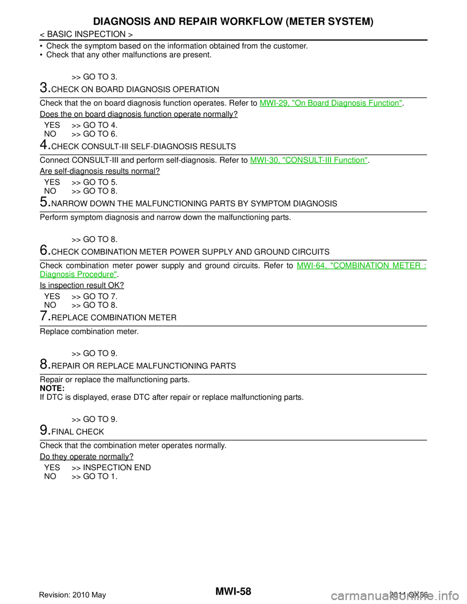
DIAGNOSIS AND REPAIR WORKFLOW (METER SYSTEM)
Check the symptom based on the inform ation obtained from the customer.
Check that any other malfunctions are present.
>> GO TO 3.
3.CHECK ON BOARD DIAGNOSIS OPERATION
Check that the on board diagnosis function operates. Refer to MWI-29, "
On Board Diagnosis Function".
Does the on board diagnosis function operate normally?
YES >> GO TO 4.
NO >> GO TO 6.
4.CHECK CONSULT-III SELF-DIAGNOSIS RESULTS
Connect CONSULT-III and perform self-diagnosis. Refer to MWI-30, "
CONSULT-III Function".
Are self-diagnosis results normal?
YES >> GO TO 5.
NO >> GO TO 8.
5.NARROW DOWN THE MALFUNCTIONING PARTS BY SYMPTOM DIAGNOSIS
Perform symptom diagnosis and narrow down the malfunctioning parts.
>> GO TO 8.
6.CHECK COMBINATION METER POWE R SUPPLY AND GROUND CIRCUITS
Check combination meter power supply and ground circuits. Refer to MWI-64, "
COMBINATION METER :
Diagnosis Procedure".
Is inspection result OK?
YES >> GO TO 7.
NO >> GO TO 8.
7.REPLACE COMBINATION METER
Replace combination meter.
>> GO TO 9.
8.REPAIR OR REPLACE MALFUNCTIONING PARTS
Repair or replace the malfunctioning parts.
NOTE:
If DTC is displayed, erase DTC after repair or replace malfunctioning parts.
>> GO TO 9.
9.FINAL CHECK
Check that the combination meter operates normally.
Do they operate normally?
YES >> INSPECTION END
NO >> GO TO 1.
Revision: 2010 May2011 QX56
Page 3802 of 5598

MWI
U1000 CAN COMM CIRCUITMWI-59
< DTC/CIRCUIT DIAGNOSIS >
C
DE
F
G H
I
J
K L
M B A
O P
DTC/CIRCUIT DIAGNOSIS
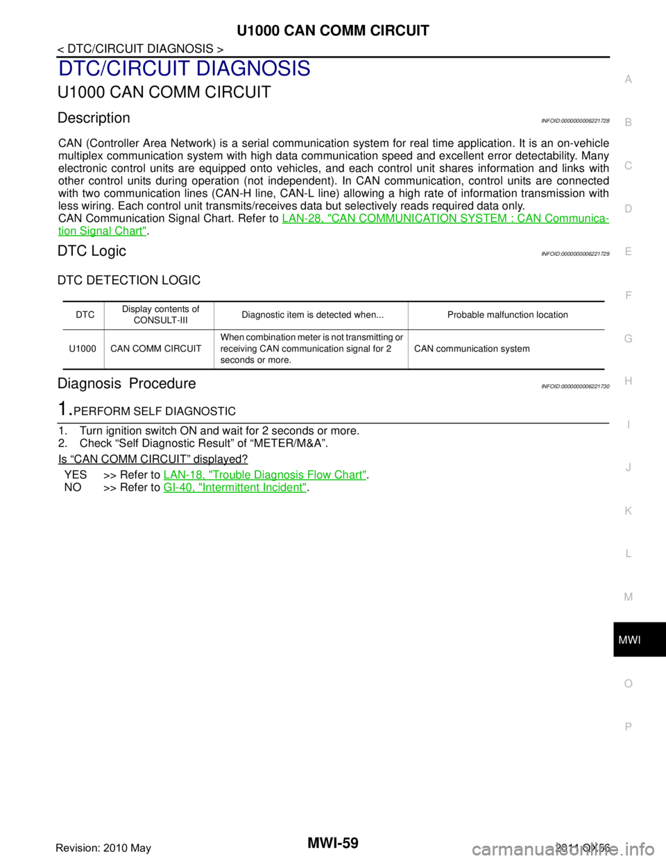
U1000 CAN COMM CIRCUIT
DescriptionINFOID:0000000006221728
CAN (Controller Area Network) is a serial communication system for real time application. It is an on-vehicle
multiplex communication system with high data communi cation speed and excellent error detectability. Many
electronic control units are equipped onto vehicles, and each control unit shares information and links with
other control units during operation (not independent). In CAN communication, control units are connected
with two communication lines (CAN-H line, CAN-L line) allowing a high rate of information transmission with
less wiring. Each control unit transmits/receives data but selectively reads required data only.
CAN Communication Signal Chart. Refer to LAN-28, "
CAN COMMUNICATION SYSTEM : CAN Communica-
tion Signal Chart".
DTC LogicINFOID:0000000006221729
DTC DETECTION LOGIC
Diagnosis ProcedureINFOID:0000000006221730
1.PERFORM SELF DIAGNOSTIC
1. Turn ignition switch ON and wait for 2 seconds or more.
2. Check “Self Diagnostic Result” of “METER/M&A”.
Is
“CAN COMM CIRCUIT” displayed?
YES >> Refer to LAN-18, "Trouble Diagnosis Flow Chart".
NO >> Refer to GI-40, "
Intermittent Incident".
DTCDisplay contents of
CONSULT-III Diagnostic item is detected when... Probable malfunction location
U1000 CAN COMM CIRCUIT When combination meter is not transmitting or
receiving CAN communication signal for 2
seconds or more.
CAN communication system
Revision: 2010 May2011 QX56
Page 3803 of 5598
MWI-60
< DTC/CIRCUIT DIAGNOSIS >
U1010 CONTROL UNIT (CAN)
U1010 CONTROL UNIT (CAN)
DescriptionINFOID:0000000006221731
Initial diagnosis of combination meter.
DTC LogicINFOID:0000000006221732
DTC DETECTION LOGIC
Diagnosis ProcedureINFOID:0000000006221733
1.REPLACE COMBINATION METER
When DTC “U1010” is detected, replace combination meter.
>> INSPECTION END
DTCDisplay contents of CON-
SULT-III Diagnostic item is detected when... Probable malfunction location
U1010 CONTROL UNIT (CAN) When detecting error during the initial diagno-
sis of the CAN controller of combination
meter.
Combination meter
Revision: 2010 May2011 QX56
Page 3804 of 5598
MWI
B2205 VEHICLE SPEEDMWI-61
< DTC/CIRCUIT DIAGNOSIS >
C
DE
F
G H
I
J
K L
M B A
O P
B2205 VEHICLE SPEED
DescriptionINFOID:0000000006221734
Vehicle speed signal is transmitted from ABS actuator and electric unit (control unit) via CAN communication
to combination meter.
DTC LogicINFOID:0000000006221735
DTC DETECTION LOGIC
Diagnosis ProcedureINFOID:0000000006221736
1.PERFORM SELF-DIAGNOSIS OF ABS ACTUAT OR AND ELECTRIC UNIT (CONTROL UNIT)
Perform “Self Diagnostic Result” of ABS actuator and electric unit (control unit), and repair or replace malfunc-
tioning parts.
>> Refer to BRC-51, "
DTC Index".
DTCDisplay contents of
CONSULT-III Diagnostic item is detected when... Probable malfunction location
B2205 VEHICLE SPEED An abnormal vehicle speed signal is input
from ABS actuator and electric unit (control
unit) for 2 seconds or more Wheel sensor
ABS actuator and electric
unit (control unit)
Revision: 2010 May2011 QX56
Page 3805 of 5598
MWI-62
< DTC/CIRCUIT DIAGNOSIS >
B2267 ENGINE SPEED
B2267 ENGINE SPEED
DescriptionINFOID:0000000006221737
The engine speed signal is transmitted from ECM to the combination meter via CAN communication.
DTC LogicINFOID:0000000006221738
DTC DETECTION LOGIC
Diagnosis ProcedureINFOID:0000000006221739
1.PERFORM SELF-DIAGNOSIS OF ECM
Perform “Self Diagnostic Result” of ECM, and repair or replace malfunctioning parts.
>> Refer to EC-98, "
DTC Index".
DTCDisplay contents of
CONSULT-III Diagnostic item is detected when... Probable malfunction location
B2267 ENGINE SPEED ECM continuously transmits abnormal engine
speed signals for 2 seconds or more Crankshaft position sensor (POS)
ECM
Revision: 2010 May2011 QX56