2011 INFINITI QX56 display
[x] Cancel search: displayPage 3806 of 5598
MWI
B2268 WATER TEMPMWI-63
< DTC/CIRCUIT DIAGNOSIS >
C
DE
F
G H
I
J
K L
M B A
O P
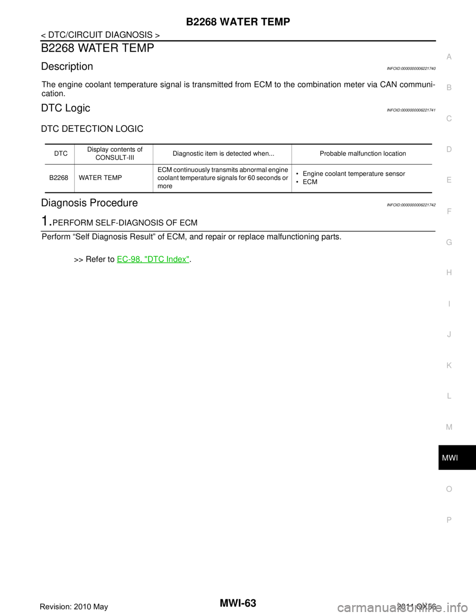
B2268 WATER TEMP
DescriptionINFOID:0000000006221740
The engine coolant temperature signal is transmitted from ECM to the combination meter via CAN communi-
cation.
DTC LogicINFOID:0000000006221741
DTC DETECTION LOGIC
Diagnosis ProcedureINFOID:0000000006221742
1.PERFORM SELF-DIAGNOSIS OF ECM
Perform “Self Diagnosis Result” of ECM, and repair or replace malfunctioning parts.
>> Refer to EC-98, "
DTC Index".
DTCDisplay contents of
CONSULT-III Diagnostic item is detected when... Probable malfunction location
B2268 WATER TEMP ECM continuously transmits abnormal engine
coolant temperature signals for 60 seconds or
more Engine coolant temperature sensor
ECM
Revision: 2010 May2011 QX56
Page 3823 of 5598
MWI-80
< SYMPTOM DIAGNOSIS >
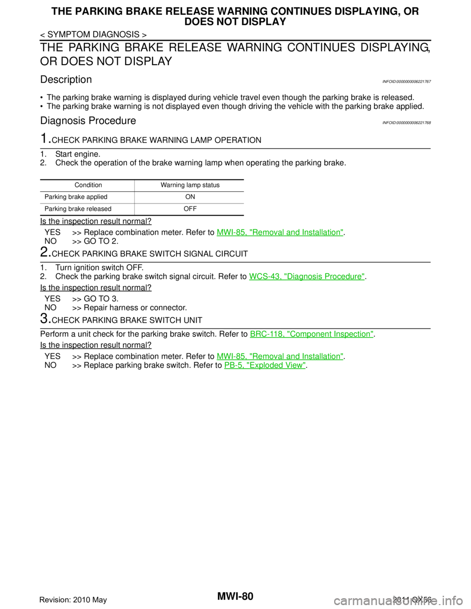
THE PARKING BRAKE RELEASE WARNING CONTINUES DISPLAYING, OR
DOES NOT DISPLAY
THE PARKING BRAKE RELEASE WA RNING CONTINUES DISPLAYING,
OR DOES NOT DISPLAY
DescriptionINFOID:0000000006221767
The parking brake warning is displayed during vehi cle travel even though the parking brake is released.
The parking brake warning is not displayed even though driving the vehicle with the parking brake applied.
Diagnosis ProcedureINFOID:0000000006221768
1.CHECK PARKING BRAKE WARNING LAMP OPERATION
1. Start engine.
2. Check the operation of the brake warni ng lamp when operating the parking brake.
Is the inspection result normal?
YES >> Replace combination meter. Refer to MWI-85, "Removal and Installation".
NO >> GO TO 2.
2.CHECK PARKING BRAKE SWITCH SIGNAL CIRCUIT
1. Turn ignition switch OFF.
2. Check the parking brake switch signal circuit. Refer to WCS-43, "
Diagnosis Procedure".
Is the inspection result normal?
YES >> GO TO 3.
NO >> Repair harness or connector.
3.CHECK PARKING BRAKE SWITCH UNIT
Perform a unit check for the parking brake switch. Refer to BRC-118, "
Component Inspection".
Is the inspection result normal?
YES >> Replace combination meter. Refer to MWI-85, "Removal and Installation".
NO >> Replace parking brake switch. Refer to PB-5, "
Exploded View".
Condition Warning lamp status
Parking brake applied ON
Parking brake released OFF
Revision: 2010 May2011 QX56
Page 3824 of 5598
MWI
THE LOW WASHER FLUID WARNING CONTINUES DISPLAYING, OR DOES
NOT DISPLAY
MWI-81
< SYMPTOM DIAGNOSIS >
C
DE
F
G H
I
J
K L
M B A
O P
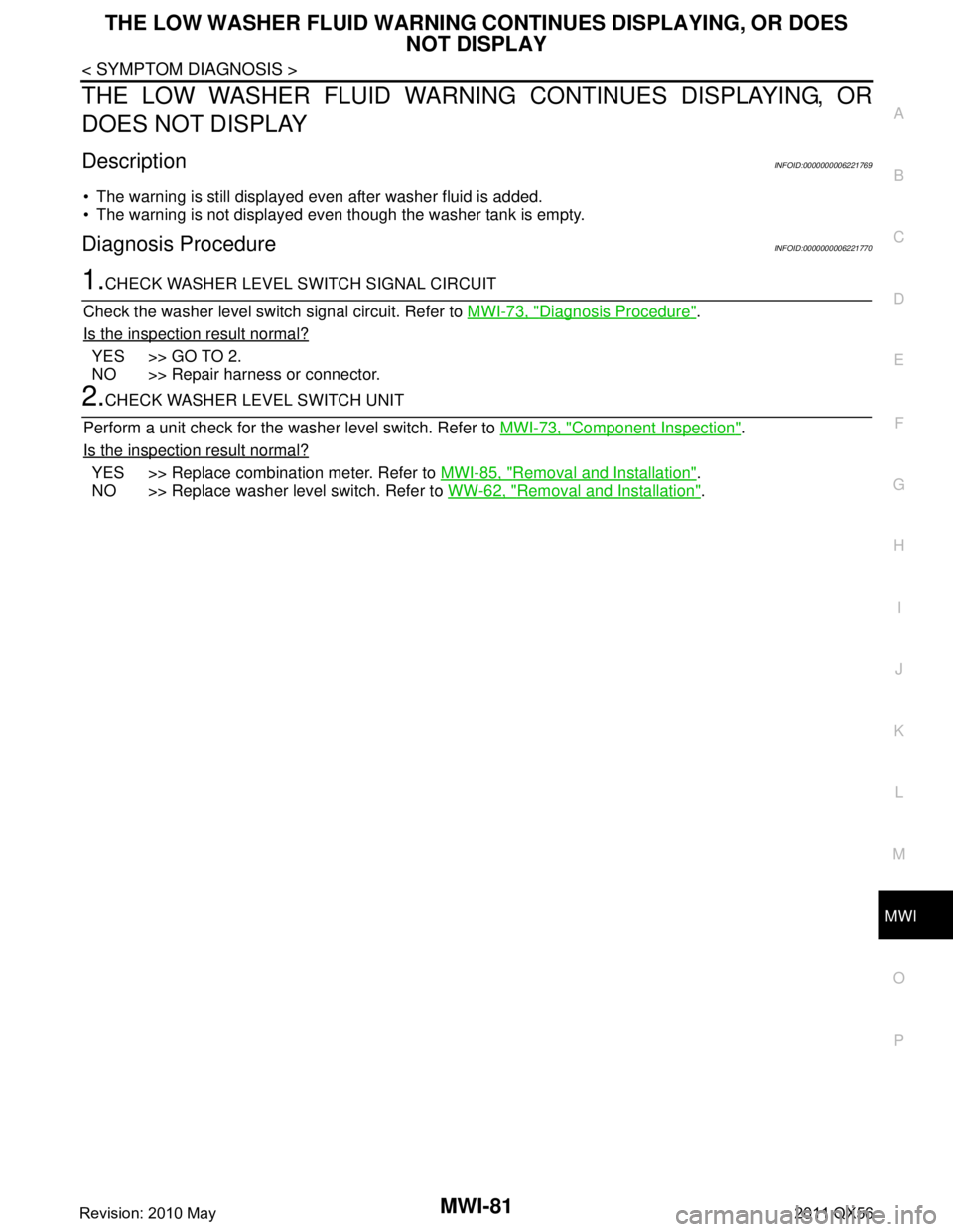
THE LOW WASHER FLUID WARNING CONTINUES DISPLAYING, OR
DOES NOT DISPLAY
DescriptionINFOID:0000000006221769
The warning is still displayed even after washer fluid is added.
The warning is not displayed even though the washer tank is empty.
Diagnosis ProcedureINFOID:0000000006221770
1.CHECK WASHER LEVEL SWITCH SIGNAL CIRCUIT
Check the washer level switch signal circuit. Refer to MWI-73, "
Diagnosis Procedure".
Is the inspection result normal?
YES >> GO TO 2.
NO >> Repair harness or connector.
2.CHECK WASHER LEVEL SWITCH UNIT
Perform a unit check for the washer level switch. Refer to MWI-73, "
Component Inspection".
Is the inspection result normal?
YES >> Replace combination meter. Refer to MWI-85, "Removal and Installation".
NO >> Replace washer level switch. Refer to WW-62, "
Removal and Installation".
Revision: 2010 May2011 QX56
Page 3825 of 5598
MWI-82
< SYMPTOM DIAGNOSIS >
THE DOOR OPEN WARNING CONTINUES DISPLAYING, OR DOES NOT DIS-
PLAY
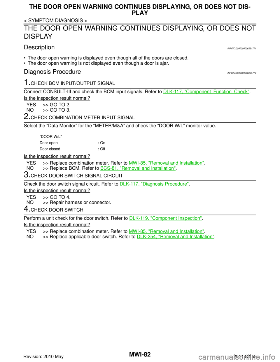
THE DOOR OPEN WARNING CONTIN UES DISPLAYING, OR DOES NOT
DISPLAY
DescriptionINFOID:0000000006221771
The door open warning is displayed even though all of the doors are closed.
The door open warning is not displayed even though a door is ajar.
Diagnosis ProcedureINFOID:0000000006221772
1.CHECK BCM INPUT/OUTPUT SIGNAL
Connect CONSULT-III and check the BCM input signals. Refer to DLK-117, "
ComponentFunctionCheck".
Is the inspection result normal?
YES >> GO TO 2.
NO >> GO TO 3.
2.CHECK COMBINATION METER INPUT SIGNAL
Select the “Data Monitor” for the “METER/M&A” and check the “DOOR W/L” monitor value.
Is the inspection result normal?
YES >> Replace combination meter. Refer to MWI-85, "Removal and Installation".
NO >> Replace BCM. Refer to BCS-81, "
Removal and Installation".
3.CHECK DOOR SWITCH SIGNAL CIRCUIT
Check the door switch signal circuit. Refer to DLK-117, "
Diagnosis Procedure".
Is the inspection result normal?
YES >> GO TO 4.
NO >> Repair harness or connector.
4.CHECK DOOR SWITCH
Perform a unit check for the door switch. Refer to DLK-119, "
Component Inspection".
Is the inspection result normal?
YES >> Replace combination meter. Refer to MWI-85, "Removal and Installation".
NO >> Replace applicable door switch. Refer to DLK-254, "
Removal and Installation".
“DOOR W/L”
Door open : On
Door closed : Off
Revision: 2010 May2011 QX56
Page 3826 of 5598
MWI
THE AMBIENT TEMPERATURE DISPLAY IS INCORRECT
MWI-83
< SYMPTOM DIAGNOSIS >
C
D E
F
G H
I
J
K L
M B A
O P
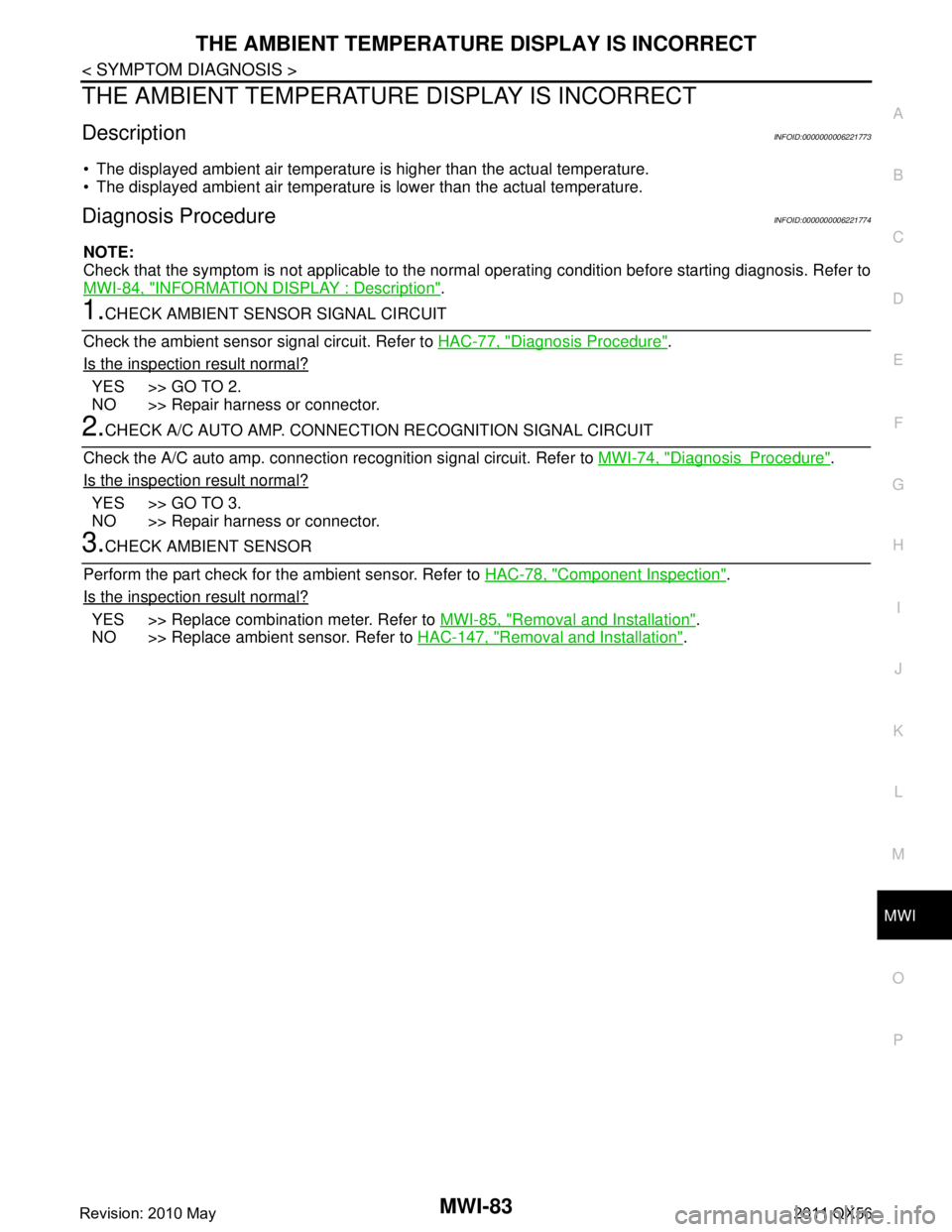
THE AMBIENT TEMPERATURE DISPLAY IS INCORRECT
DescriptionINFOID:0000000006221773
The displayed ambient air temperature is higher than the actual temperature.
The displayed ambient air temperature is lower than the actual temperature.
Diagnosis ProcedureINFOID:0000000006221774
NOTE:
Check that the symptom is not applicable to the no rmal operating condition before starting diagnosis. Refer to
MWI-84, "
INFORMATION DISPLAY : Description".
1.CHECK AMBIENT SENSOR SIGNAL CIRCUIT
Check the ambient sensor signal circuit. Refer to HAC-77, "
Diagnosis Procedure".
Is the inspection result normal?
YES >> GO TO 2.
NO >> Repair harness or connector.
2.CHECK A/C AUTO AMP. CONNECTION RECOGNITION SIGNAL CIRCUIT
Check the A/C auto amp. connection re cognition signal circuit. Refer to MWI-74, "
DiagnosisProcedure".
Is the inspection result normal?
YES >> GO TO 3.
NO >> Repair harness or connector.
3.CHECK AMBIENT SENSOR
Perform the part check for t he ambient sensor. Refer to HAC-78, "
Component Inspection".
Is the inspection result normal?
YES >> Replace combination meter. Refer to MWI-85, "Removal and Installation".
NO >> Replace ambient sensor. Refer to HAC-147, "
Removal and Installation".
Revision: 2010 May2011 QX56
Page 3827 of 5598

MWI-84
< SYMPTOM DIAGNOSIS >
NORMAL OPERATING CONDITION
NORMAL OPERATING CONDITION
INFORMATION DISPLAY
INFORMATION DISPLAY : DescriptionINFOID:0000000006221775
AMBIENT AIR TEMPERATURE
The displayed ambient air temperature on the information display may differ from the actual temperature
because it is a corrected value calculated from the ambi ent sensor signal by the combination meter. Refer to
MWI-20, "
INFORMATION DISPLAY : System Description" for details on the correction process.
DISTANCE TO EMPTY
The calculated distance to empty may differ from the actual distance to empty if the refueling amount is
approximately 15 (4 US gal, 3-1/4 Imp gal) or less. Th is is because the refuel control (moves the fuel gauge
needle quicker than normal judging that the driver is refueling the vehicle) is not performing.
Revision: 2010 May2011 QX56
Page 3848 of 5598
![INFINITI QX56 2011 Factory Service Manual
PCS
SYSTEMPCS-7
< SYSTEM DESCRIPTION > [IPDM E/R]
C
D
E
F
G H
I
J
K L
B A
O P
N
IGNITION RELAY MALFUNCTION DETECTION FUNCTION
IPDM E/R monitors the voltage at the contact circuit and
excitation co INFINITI QX56 2011 Factory Service Manual
PCS
SYSTEMPCS-7
< SYSTEM DESCRIPTION > [IPDM E/R]
C
D
E
F
G H
I
J
K L
B A
O P
N
IGNITION RELAY MALFUNCTION DETECTION FUNCTION
IPDM E/R monitors the voltage at the contact circuit and
excitation co](/manual-img/42/57033/w960_57033-3847.png)
PCS
SYSTEMPCS-7
< SYSTEM DESCRIPTION > [IPDM E/R]
C
D
E
F
G H
I
J
K L
B A
O P
N
IGNITION RELAY MALFUNCTION DETECTION FUNCTION
IPDM E/R monitors the voltage at the contact circuit and
excitation coil circuit of the ignition relay inside it.
IPDM E/R judges the ignition relay error if the volt age differs between the contact circuit and the excitation
coil circuit.
If the ignition relay cannot turn OFF due to contact seizure, it activates the tail lamp relay for 10 minutes to alert the user to the ignition relay malfunc tion when the ignition switch is turned OFF.
FRONT WIPER PROTECTION FUNCTION
IPDM E/R detects front wiper stop position by a front wiper stop position signal.
When a front wiper stop position signal is in the conditi ons listed below, IPDM E/R stops power supply to wiper
after repeating a front wiper 10 seconds activation and 20 seconds stop.
NOTE:
This operation status can be confirmed on the IPDM E/ R “Data Monitor” that displays “BLOCK” for the item
“WIP PROT” while the wiper is stopped.
STARTER MOTOR PROTECTION FUNCTION
IPDM E/R turns OFF the starter control relay to protect the starter motor when the starter control relay remains
active for 90 seconds.
POWER CONTROL SYSTEM
Control part Fail-safe operation
Headlamp Turns ON the headlamp low relay when the ignition switch is turned ON
Turns OFF the headlamp low relay when the ignition switch is turned OFF
Headlamp high relay OFF
Parking lamp
License plate lamp
Illumination
Tail lamp Turns ON the tail lamp relay when the ignition switch is turned ON
Turns OFF the tail lamp relay when the ignition switch is turned OFF
Front wiper motor The status just before activation of fail-safe control is maintained until the ignition switch is
turned OFF while the front wiper is operating at LO or HI speed.
The wiper is operated at LO speed until the ignition switch is turned OFF if the fail-safe con- trol is activated while the front wiper is set in the INT mode and the front wiper motor is op-
erating.
Return automatically wiper to stop position when ignition switch is turned ON if fail-safe con- trol is activated while front wiper motor is operated and wiper stops in the other position than
stop position.
Front fog lamp Front fog lamp relay OFF
Horn Horn OFF
Ignition relay The status just before activation of fail-safe is maintained.
Starter motor Starter control relay OFF
Steering lock unit Steering lock relay OFF
Voltage judgment IPDM E/R judgment Operation
Ignition relay contact side Ignition relay excitation coil
side
ON ON Ignition relay ON normal —
OFF OFF Ignition relay OFF normal —
ON OFF Ignition relay ON stuck Detects DTC “B2098: IGN RELAY ON”
Turns ON the tail lamp relay for 10 min-
utes
OFF ON Ignition relay OFF stuck Detects DTC “B2099: IGN RELAY OFF”
Ignition switch Front wiper switch Front wiper stop position signal
ON OFF
The front wiper stop position signal (stop position) cannot be input for
10 seconds.
ON The front wiper stop position signal does not change for 10 seconds.
Revision: 2010 May2011 QX56
Page 3853 of 5598
![INFINITI QX56 2011 Factory Service Manual
PCS-12
< SYSTEM DESCRIPTION >[IPDM E/R]
DIAGNOSIS SYSTEM (IPDM E/R)
CONSULT-III Function (IPDM E/R)
INFOID:0000000006220171
APPLICATION ITEM
CONSULT-III performs the following functions via CAN commu INFINITI QX56 2011 Factory Service Manual
PCS-12
< SYSTEM DESCRIPTION >[IPDM E/R]
DIAGNOSIS SYSTEM (IPDM E/R)
CONSULT-III Function (IPDM E/R)
INFOID:0000000006220171
APPLICATION ITEM
CONSULT-III performs the following functions via CAN commu](/manual-img/42/57033/w960_57033-3852.png)
PCS-12
< SYSTEM DESCRIPTION >[IPDM E/R]
DIAGNOSIS SYSTEM (IPDM E/R)
CONSULT-III Function (IPDM E/R)
INFOID:0000000006220171
APPLICATION ITEM
CONSULT-III performs the following functions via CAN communication with IPDM E/R.
SELF DIAGNOSTIC RESULT
Refer to PCS-22, "DTCIndex".
DATA MONITOR
Monitor item
Oil pressure warning lamp does not operate Perform auto active test.
Does the oil pressure warning
lamp blink?YES
Harness or connector be-
tween IPDM E/R and oil
pressure switch
Oil pressure switch
IPDM E/R
NO CAN communication signal
between IPDM E/R and
BCM
CAN communication signal
between BCM and combi-
nation meter
Combination meter
Symptom Inspection contents Possible cause
Diagnosis mode Description
Ecu Identification Allows confirmation of IPDM E/R part number.
Self Diagnostic Result Displays the diagnosis results judged by IPDM E/R.
Data Monitor Displays the real-time input/output data from IPDM E/R input/output data.
Active Test IPDM E/R can provide a drive signal to electronic components to check their operations.
CAN Diag Support Monitor The results of transmit/receive diagnosis of CAN communication can be read.
Monitor Item [Unit] MAIN SIG-
NALS Description
RAD FAN REQ
[1/2/3/4] ×Displays the value of the cooling fan speed request signal received from ECM via
CAN communication.
AC COMP REQ
[Off/On] ×Displays the status of the A/C compressor request signal received from ECM via
CAN communication.
TA I L & C L R R E Q
[Off/On] ×
Displays the status of the position light request signal received from BCM via CAN
communication.
HL LO REQ
[Off/On] ×Displays the status of the low beam request signal received from BCM via CAN
communication.
HL HI REQ
[Off/On] ×Displays the status of the high beam request signal received from BCM via CAN
communication.
FR FOG REQ
[Off/On] ×Displays the status of the front fog light request signal received from BCM via
CAN communication.
FR WIP REQ
[Stop/1LOW/Low/Hi] ×
Displays the status of the front wiper request signal received from BCM via CAN
communication.
WIP AUTO STOP
[STOP P/ACT P] ×
Displays the status of the front wiper auto stop signal judged by IPDM E/R.
WIP PROT
[Off/BLOCK] ×
Displays the status of the front wiper fail-safe operation judged by IPDM E/R.
IGN RLY1 -REQ
[Off/On] Displays the status of the ignition switch ON signal received from BCM via CAN
communication.
IGN RLY
[Off/On] ×
Displays the status of the ignition relay judged by IPDM E/R.
Revision: 2010 May2011 QX56