2011 INFINITI QX56 display
[x] Cancel search: displayPage 3534 of 5598
![INFINITI QX56 2011 Factory Service Manual
LAN-114
< DTC/CIRCUIT DIAGNOSIS >[CAN GATEWAY]
U1010 CONTROL UNIT (CAN)
U1010 CONTROL UNIT (CAN)
DescriptionINFOID:0000000006220588
CAN (Controller Area Network) is a serial communication
line for r INFINITI QX56 2011 Factory Service Manual
LAN-114
< DTC/CIRCUIT DIAGNOSIS >[CAN GATEWAY]
U1010 CONTROL UNIT (CAN)
U1010 CONTROL UNIT (CAN)
DescriptionINFOID:0000000006220588
CAN (Controller Area Network) is a serial communication
line for r](/manual-img/42/57033/w960_57033-3533.png)
LAN-114
< DTC/CIRCUIT DIAGNOSIS >[CAN GATEWAY]
U1010 CONTROL UNIT (CAN)
U1010 CONTROL UNIT (CAN)
DescriptionINFOID:0000000006220588
CAN (Controller Area Network) is a serial communication
line for real time applications. It is an on-vehicle mul-
tiplex communication line with high data communication speed and excellent error detection ability. Modern
vehicle is equipped with many electronic control unit, and each control unit shares information and links with
other control units during operation (not independent). In CAN communication, control units are connected
with two communication lines (CAN-H and CAN-L) allo wing a high rate of information transmission with less
wiring. Each control unit transmits/receives data but selectively reads required data only.
CAN Communication Signal Chart. Refer to LAN-28, "
CAN COMMUNICATION SYSTEM : CAN Communica-
tion Signal Chart".
DTC LogicINFOID:0000000006220589
DTC DETECTION LOGIC
Diagnosis ProcedureINFOID:0000000006220590
1.REPLACE CAN GATEWAY
When DTC “U1010: CONTROL UNIT(CAN)” is detected, replace CAN gateway.
>> Replace CAN gateway. Refer to LAN-117, "
Removal and Installation".
DTCCONSULT-III display
description DTC Detection
Condition Possible cause
U1010 CONTROL UNIT(CAN) When an error is detected during the initial di-
agnosis for CAN contro
ller of CAN gateway. CAN gateway
Revision: 2010 May2011 QX56
Page 3535 of 5598
![INFINITI QX56 2011 Factory Service Manual
LAN
B2600 CONFIG ERRORLAN-115
< DTC/CIRCUIT DIAGNOSIS > [CAN GATEWAY]
C
D
E
F
G H
I
J
K L
B A
O P
N
B2600 CONFIG ERROR
DescriptionINFOID:0000000006220591
The CAN gateway requires initial settings to INFINITI QX56 2011 Factory Service Manual
LAN
B2600 CONFIG ERRORLAN-115
< DTC/CIRCUIT DIAGNOSIS > [CAN GATEWAY]
C
D
E
F
G H
I
J
K L
B A
O P
N
B2600 CONFIG ERROR
DescriptionINFOID:0000000006220591
The CAN gateway requires initial settings to](/manual-img/42/57033/w960_57033-3534.png)
LAN
B2600 CONFIG ERRORLAN-115
< DTC/CIRCUIT DIAGNOSIS > [CAN GATEWAY]
C
D
E
F
G H
I
J
K L
B A
O P
N
B2600 CONFIG ERROR
DescriptionINFOID:0000000006220591
The CAN gateway requires initial settings to judge necessa
ry information, according to a vehicle specification.
DTC LogicINFOID:0000000006220592
DTC DETECTION LOGIC
Diagnosis ProcedureINFOID:0000000006220593
1.REPLACE CAN GATEWAY
When DTC “B2600: CONFIG ERROR” is detected, replace CAN gateway.
>> Replace CAN gateway. Refer to LAN-117, "
Removal and Installation".
DTCCONSULT-III display
description DTC Detection Condit
ion Probable cause
B2600 CONFIG ERROR
WRONG DATA
When errors are detected in the configuration
data stored in the CAN gateway.
CAN gateway
CONFIG ERROR
NOT CONFIGURED When no data are stored in the CAN gateway.
Revision: 2010 May2011 QX56
Page 3744 of 5598

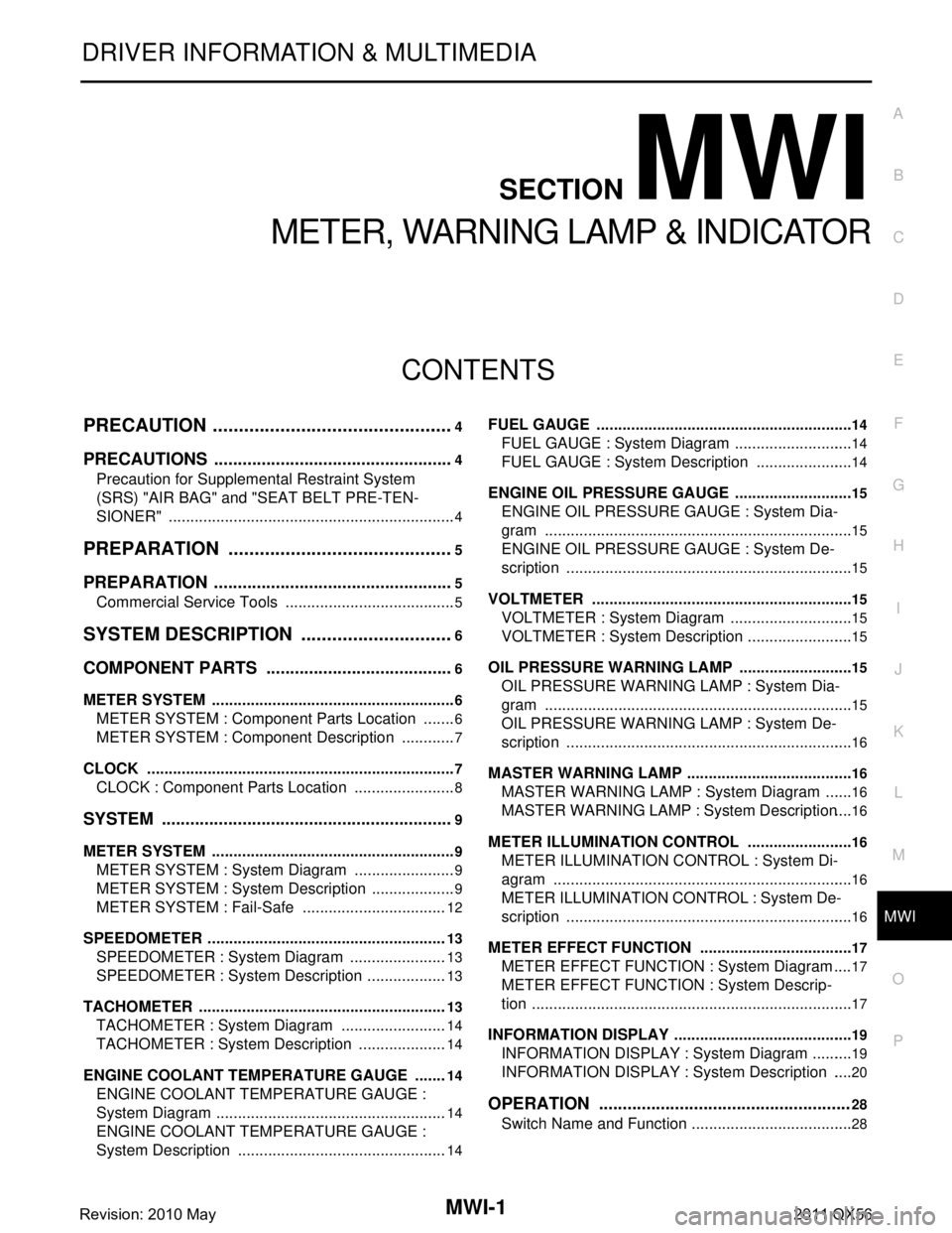
MWI
MWI-1
DRIVER INFORMATION & MULTIMEDIA
C
DE
F
G H
I
J
K L
M B
SECTION MWI
A
O P
CONTENTS
METER, WARNING LAMP & INDICATOR
PRECAUTION ................ ...............................4
PRECAUTIONS .............................................. .....4
Precaution for Supplemental Restraint System
(SRS) "AIR BAG" and "SEAT BELT PRE-TEN-
SIONER" ............................................................. ......
4
PREPARATION ............................................5
PREPARATION .............................................. .....5
Commercial Service Tools .................................. ......5
SYSTEM DESCRIPTION ..............................6
COMPONENT PARTS ................................... .....6
METER SYSTEM .........................................................6
METER SYSTEM : Component Parts Location .. ......6
METER SYSTEM : Component Description .............7
CLOCK .................................................................. ......7
CLOCK : Component Parts Location ........................8
SYSTEM ..............................................................9
METER SYSTEM .........................................................9
METER SYSTEM : System Diagram ........................9
METER SYSTEM : System Description ....................9
METER SYSTEM : Fail-Safe ..................................12
SPEEDOMETER ................ ........................................13
SPEEDOMETER : System Diagram ................... ....13
SPEEDOMETER : System Description ...................13
TACHOMETER ...................................................... ....13
TACHOMETER : System Diagram .........................14
TACHOMETER : System Description .....................14
ENGINE COOLANT TEMPERATURE GAUGE .... ....14
ENGINE COOLANT TEMPERATURE GAUGE :
System Diagram ......................................................
14
ENGINE COOLANT TEMPERATURE GAUGE :
System Description .................................................
14
FUEL GAUGE ........................................................ ....14
FUEL GAUGE : System Diagram ............................14
FUEL GAUGE : System Description .......................14
ENGINE OIL PRESSURE GAUGE ............................15
ENGINE OIL PRESSURE GAUGE : System Dia-
gram .................................................................... ....
15
ENGINE OIL PRESSURE GAUGE : System De-
scription ...................................................................
15
VOLTMETER ......................................................... ....15
VOLTMETER : System Diagram .............................15
VOLTMETER : System Description .........................15
OIL PRESSURE WARNING LAMP ...........................15
OIL PRESSURE WARNING LAMP : System Dia-
gram .................................................................... ....
15
OIL PRESSURE WARNING LAMP : System De-
scription ...................................................................
16
MASTER WARNING LAMP ................................... ....16
MASTER WARNING LAMP : System Diagram .......16
MASTER WARNING LAMP : System Description ....16
METER ILLUMINATION CONTROL ..................... ....16
METER ILLUMINATION CONTROL : System Di-
agram ......................................................................
16
METER ILLUMINATION CONTROL : System De-
scription ...................................................................
16
METER EFFECT FUNCTION ................................ ....17
METER EFFECT FUNCTION : System Diagram ....17
METER EFFECT FUNCTION : System Descrip-
tion ...........................................................................
17
INFORMATION DISPLAY ...................................... ....19
INFORMATION DISPLAY : System Diagram ..........19
INFORMATION DISPLAY : System Description .....20
OPERATION .....................................................28
Switch Name and Function ......................................28
Revision: 2010 May2011 QX56
Page 3745 of 5598

MWI-2
DIAGNOSIS SYSTEM (COMBINATION
METER) ..............................................................
29
On Board Diagnosis Function .............................. ...29
CONSULT-III Function ...........................................30
ECU DIAGNOSIS INFORMATION ..............35
COMBINATION METER ................................. ...35
Reference Value .................................................. ...35
Fail-Safe .................................................................42
DTC Index ..............................................................43
IPDM E/R ...........................................................44
List of ECU Reference ......................................... ...44
WIRING DIAGRAM .....................................45
METER SYSTEM ............................................ ...45
Wiring Diagram .................................................... ...45
CLOCK ...............................................................55
Wiring Diagram .................................................... ...55
BASIC INSPECTION ...................................57
DIAGNOSIS AND REPAIR WORKFLOW
(METER SYSTEM ) .......................................... ...
57
Work flow ............................................................. ...57
DTC/CIRCUIT DIAGNOSIS ...................... ...59
U1000 CAN COMM CIRCUIT ......................... ...59
Description ........................................................... ...59
DTC Logic ...............................................................59
Diagnosis Procedure .............................................59
U1010 CONTROL UNIT (CAN) .........................60
Description ........................................................... ...60
DTC Logic ...............................................................60
Diagnosis Procedure ..............................................60
B2205 VEHICLE SPEED ...................................61
Description ........................................................... ...61
DTC Logic ...............................................................61
Diagnosis Procedure .............................................61
B2267 ENGINE SPEED .....................................62
Description ........................................................... ...62
DTC Logic ...............................................................62
Diagnosis Procedure ..............................................62
B2268 WATER TEMP ........................................63
Description ........................................................... ...63
DTC Logic ...............................................................63
Diagnosis Procedure ..............................................63
POWER SUPPLY AND GROUND CIRCUIT .....64
COMBINATION METER ........................................ ...64
COMBINATION METER : Diagnosis Procedure ....64
TRIP RESET AND ILLUMINATION CON-
TROL SWITCH SIGNAL CIRCUIT ....................
65
Diagnosis Procedure ............................................ ...65
Component Inspection ............................................66
TRIP COMPUTER SWITCH SIGNAL CIRCUIT
...
67
Diagnosis Procedure ............................................ ...67
Component Inspection ............................................68
FUEL LEVEL SENSOR SIGNAL CIRCUIT .......69
Component Function Check ................................ ...69
Diagnosis Procedure ..............................................69
Component Inspection ............................................70
OIL PRESSURE SWITCH SIGNAL CIRCUIT ...71
Component Function Check ...................................71
Diagnosis Procedure ...............................................71
Component Inspection ............................................71
WASHER LEVEL SWITCH SIGNAL CIRCUIT ...73
Diagnosis Procedure ............................................ ...73
Component Inspection ............................................73
A/C AUTO AMP. CONNECTION RECOGNI-
TION SIGNAL CIRCUIT ....................................
74
Diagnosis Procedure ........................................... ...74
SYMPTOM DIAGNOSIS ............................75
THE FUEL GAUGE INDICATOR DOES NOT
OPERATE ....................................................... ...
75
Description ........................................................... ...75
Diagnosis Procedure ...............................................75
THE TRIP RESET AND ILLUMINATION CON-
TROL SWITCH IS INOPERATIVE ....................
76
Description ........................................................... ...76
Diagnosis Procedure ...............................................76
THE TRIP COMPUTER SWITCH IS INOPER-
ATIVE .................................................................
77
Description ........................................................... ...77
Diagnosis Procedure ...............................................77
THE OIL PRESSURE WARNING LAMP
DOES NOT TURN ON .................................... ...
78
Description ........................................................... ...78
Diagnosis Procedure ...............................................78
THE OIL PRESSURE WARNING LAMP
DOES NOT TURN OFF .................................. ...
79
Description ........................................................... ...79
Diagnosis Procedure ...............................................79
THE PARKING BRAKE RELEASE WARNING
CONTINUES DISPLAYING, OR DOES NOT
DISPLAY ............................................................
80
Description ........................................................... ...80
Diagnosis Procedure ...............................................80
Revision: 2010 May2011 QX56
Page 3746 of 5598

MWI
MWI-3
C
DE
F
G H
I
J
K L
M B
A
O P
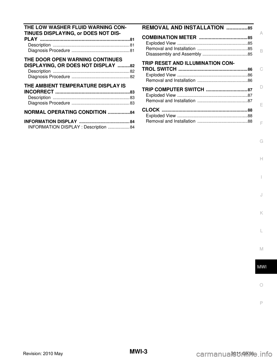
THE LOW WASHER FLUID WARNING CON-
TINUES DISPLAYING, or DOES NOT DIS-
PLAY .............................................................. ....
81
Description .......................................................... ....81
Diagnosis Procedure ...............................................81
THE DOOR OPEN WARNING CONTINUES
DISPLAYING, OR DOES NOT DISPLAY ..........
82
Description .......................................................... ....82
Diagnosis Procedure ...............................................82
THE AMBIENT TEMPERATURE DISPLAY IS
INCORRECT .......................................................
83
Description .......................................................... ....83
Diagnosis Procedure ...............................................83
NORMAL OPERATING CONDITION .................84
INFORMATION DISPLAY ..................................... ....84
INFORMATION DISPLAY : Description ..................84
REMOVAL AND INSTALLATION ...............85
COMBINATION METER ...................................85
Exploded View ..................................................... ....85
Removal and Installation .........................................85
Disassembly and Assembly .....................................85
TRIP RESET AND ILLUMINATION CON-
TROL SWITCH ..................................................
86
Exploded View .........................................................86
Removal and Installation .........................................86
TRIP COMPUTER SWITCH ..............................87
Exploded View .........................................................87
Removal and Installation .........................................87
CLOCK ..............................................................88
Exploded View .........................................................88
Removal and Installation .........................................88
Revision: 2010 May2011 QX56
Page 3750 of 5598

MWI
COMPONENT PARTSMWI-7
< SYSTEM DESCRIPTION >
C
DE
F
G H
I
J
K L
M B A
O P
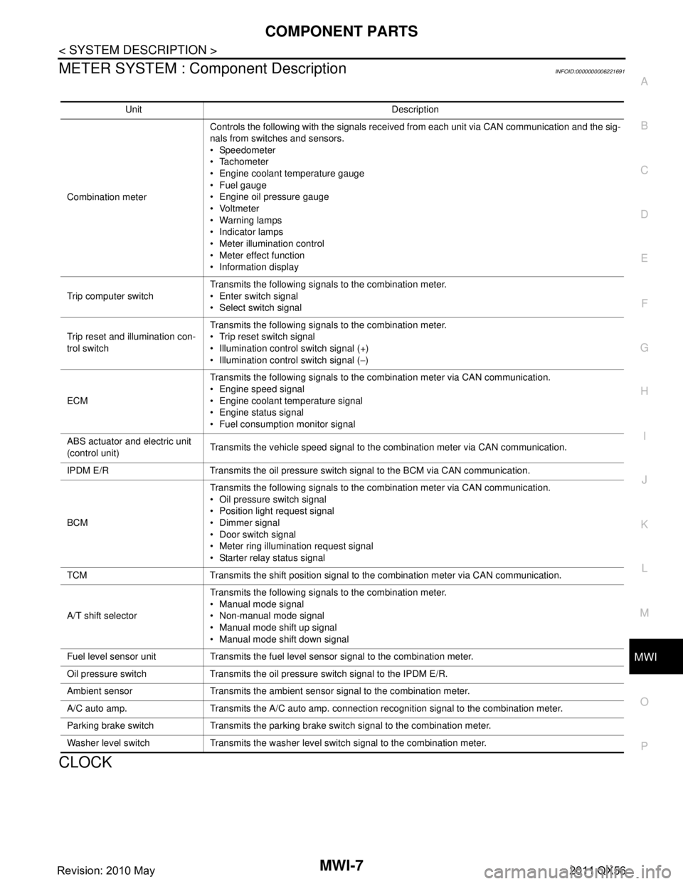
METER SYSTEM : Com ponent DescriptionINFOID:0000000006221691
CLOCK
Unit Description
Combination meter Controls the following with the signals received from each unit via CAN communication and the sig-
nals from switches and sensors.
Speedometer
Tachometer
Engine coolant temperature gauge
Fuel gauge
Engine oil pressure gauge
Voltmeter
Warning lamps
Indicator lamps
Meter illumination control
Meter effect function
Information display
Trip computer switch Transmits the following signals to the combination meter.
Enter switch signal
Select switch signal
Trip reset and illumination con-
trol switch Transmits the following signals to the combination meter.
Trip reset switch signal
Illumination control switch signal (+)
Illumination control switch signal (
−)
ECM Transmits the following signals to the combination meter via CAN communication.
Engine speed signal
Engine coolant temperature signal
Engine status signal
Fuel consumption monitor signal
ABS actuator and electric unit
(control unit) Transmits the vehicle speed signal to the combination meter via CAN communication.
IPDM E/R Transmits the oil pressure switch signal to the BCM via CAN communication.
BCM Transmits the following signals to the combination meter via CAN communication.
Oil pressure switch signal
Position light request signal
Dimmer signal
Door switch signal
Meter ring illumination request signal
Starter relay status signal
TCM Transmits the shift position signal to the combination meter via CAN communication.
A/T shift selector Transmits the following signals to the combination meter.
Manual mode signal
Non-manual mode signal
Manual mode shift up signal
Manual mode shift down signal
Fuel level sensor unit Transmits the fuel level sensor signal to the combination meter.
Oil pressure switch Transmits the oil pressure switch signal to the IPDM E/R.
Ambient sensor Transmits the ambient sensor signal to the combination meter.
A/C auto amp. Transmits the A/C auto amp. connection recognition signal to the combination meter.
Parking brake switch Transmits the parking brake switch signal to the combination meter.
Washer level switch Transmits the washer level switch signal to the combination meter.
Revision: 2010 May2011 QX56
Page 3752 of 5598

MWI
SYSTEMMWI-9
< SYSTEM DESCRIPTION >
C
DE
F
G H
I
J
K L
M B A
O P
SYSTEM
METER SYSTEM
METER SYSTEM : System DiagramINFOID:0000000006221693
METER SYSTEM : System DescriptionINFOID:0000000006221694
COMBINATION METER
The combination meter receives necessary signals from each unit, switch, and sensor to control the follow-
ing functions.
- Measuring instruments
- Warning lamps
- Indicator lamps
- Meter illumination control
- Meter effect function
- Information display
The combination meter incorporates a buzzer func tion that sounds an audible alarm with the integrated
buzzer device. Refer to WCS-5, "
Combination Meter" for further details.
The combination meter includes an on board diagnosis function.
The combination meter can be diagnosed with CONSULT-III.
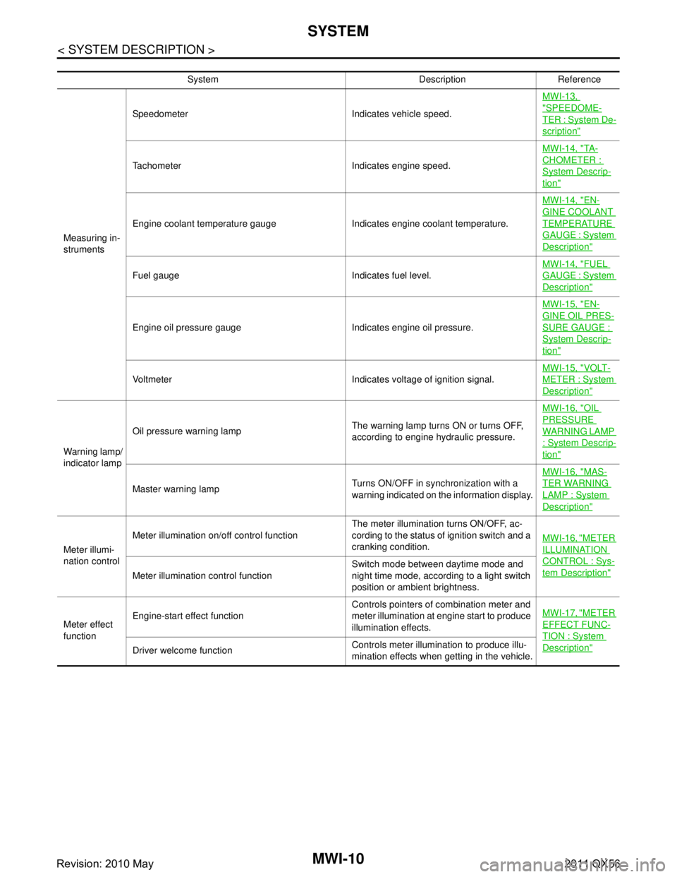
METER CONTROL FUNCTION LIST
JSNIA2995GB
Revision: 2010 May2011 QX56
Page 3753 of 5598

MWI-10
< SYSTEM DESCRIPTION >
SYSTEM
System Description Reference
Measuring in-
struments Speedometer Indicates vehicle speed.
MWI-13,
"SPEEDOME-
TER : System De-
scription"
Tachometer Indicates engine speed.MWI-14, "
TA -
CHOMETER :
System Descrip-
tion"
Engine coolant temperature gauge Indicates engine coolant temperature.MWI-14, "
EN-
GINE COOLANT
TEMPERATURE
GAUGE : System
Description"
Fuel gauge Indicates fuel level.
MWI-14, "
FUEL
GAUGE : System
Description"
Engine oil pressure gauge Indicates engine oil pressure.MWI-15, "
EN-
GINE OIL PRES-
SURE GAUGE :
System Descrip-
tion"
Voltmeter Indicates voltage of ignition signal.
MWI-15, "
VOLT-
METER : System
Description"
Warning lamp/
indicator lampOil pressure warning lamp
The warning lamp turns ON or turns OFF,
according to engine hydraulic pressure.MWI-16, "
OIL
PRESSURE
WARNING LAMP
: System Descrip-
tion"
Master warning lamp
Turns ON/OFF in synchronization with a
warning indicated on the information display.MWI-16, "
MAS-
TER WARNING
LAMP : System
Description"
Meter illumi-
nation controlMeter illumination on/off control function
The meter illumination turns ON/OFF, ac-
cording to the status of ignition switch and a
cranking condition.
MWI-16, "
METER
ILLUMINATION
CONTROL : Sys-
tem Description"Meter illumination control function Switch mode between daytime mode and
night time mode, according to a light switch
position or ambient brightness.
Meter effect
function Engine-start effect function
Controls pointers of combination meter and
meter illumination at engine start to produce
illumination effects.MWI-17, "
METER
EFFECT FUNC-
TION : System
Description"Driver welcome function
Controls meter illumination to produce illu-
mination effects when getting in the vehicle.
Revision: 2010 May2011 QX56