2011 INFINITI QX56 maintenance
[x] Cancel search: maintenancePage 2557 of 5598
![INFINITI QX56 2011 Factory Service Manual
EVAP LEAK CHECKEC-533
< PERIODIC MAINTENANCE > [VK56VD]
C
D
E
F
G H
I
J
K L
M A
EC
NP
O
5. Locate the leak using a leak detector (commercial service tool).
Refer to EC-45, "
EVAPORATIVE EMISSION SYS INFINITI QX56 2011 Factory Service Manual
EVAP LEAK CHECKEC-533
< PERIODIC MAINTENANCE > [VK56VD]
C
D
E
F
G H
I
J
K L
M A
EC
NP
O
5. Locate the leak using a leak detector (commercial service tool).
Refer to EC-45, "
EVAPORATIVE EMISSION SYS](/manual-img/42/57033/w960_57033-2556.png)
EVAP LEAK CHECKEC-533
< PERIODIC MAINTENANCE > [VK56VD]
C
D
E
F
G H
I
J
K L
M A
EC
NP
O
5. Locate the leak using a leak detector (commercial service tool).
Refer to EC-45, "
EVAPORATIVE EMISSION SYSTEM : System
Diagram".
SEF200U
Revision: 2010 May2011 QX56
Page 2558 of 5598
![INFINITI QX56 2011 Factory Service Manual
EC-534
< PERIODIC MAINTENANCE >[VK56VD]
POSITIVE CRANKCASE VENTILATION
POSITIVE CRANKCASE VENTILATION
InspectionINFOID:0000000006218033
1.CHECK PCV VALVE
With engine running at idle, remove PCV valve INFINITI QX56 2011 Factory Service Manual
EC-534
< PERIODIC MAINTENANCE >[VK56VD]
POSITIVE CRANKCASE VENTILATION
POSITIVE CRANKCASE VENTILATION
InspectionINFOID:0000000006218033
1.CHECK PCV VALVE
With engine running at idle, remove PCV valve](/manual-img/42/57033/w960_57033-2557.png)
EC-534
< PERIODIC MAINTENANCE >[VK56VD]
POSITIVE CRANKCASE VENTILATION
POSITIVE CRANKCASE VENTILATION
InspectionINFOID:0000000006218033
1.CHECK PCV VALVE
With engine running at idle, remove PCV valve from rocker cover. A
properly working valve makes a hissing noise as air passes through
it. A strong vacuum should be felt immediately when a finger is
placed over valve inlet.
Is the inspection result normal?
YES >> INSPECTION END
NO >> Replace PCV valve. Refer to EM-33, "
Exploded View".
PBIB1589E
Revision: 2010 May2011 QX56
Page 2563 of 5598
EM-1
ENGINE
C
DE
F
G H
I
J
K L
M
SECTION EM
A
EM
N
O P
CONTENTS
ENGINE MECHANICAL
PRECAUTION ................ ...............................3
PRECAUTIONS .............................................. .....3
Precaution for Procedure without Cowl Top Cover ......3
Precaution for Supplemental Restraint System
(SRS) "AIR BAG" and "SEAT BELT PRE-TEN-
SIONER" ...................................................................
3
Precaution Necessary for Steering Wheel Rota-
tion after Battery Disconnect .....................................
3
Precaution for Drain Engine Coolant and Engine
Oil ..............................................................................
4
Precaution for Disconnecting Fuel Piping .................4
Precaution for Handling High Pressure Fuel Sys-
tem ............................................................................
4
Precaution for Removal and Disassembly ................4
Precaution for Inspection, Repair and Replace-
ment ..........................................................................
4
Precaution for Assembly and Installation ..................4
Parts Requiring Angle Tightening .............................5
Precaution for Liquid Gasket .....................................5
Definitions of Bank Names ........................................6
PREPARATION ............................................7
PREPARATION .............................................. .....7
Special Service Tool ........................................... ......7
Commercial Service Tool ..........................................9
BASIC INSPECTION ...................................12
CAMSHAFT VALVE CLEARANCE ............... ....12
Inspection ............................................................ ....12
COMPRESSION PRESSURE ............................16
Inspection ............................................................ ....16
SYMPTOM DIAGNOSIS ..............................18
NOISE, VIBRATION AND HARSHNESS
(NVH) TROUBLESHOOTING ........................ ....
18
NVH Troubleshooting - Engine Noise .............. ....18
Use the Chart Below to Help You Find the C
ause of the Symptom ........................................ ....
19
PERIODIC MAINTENANCE ........................20
DRIVE BELTS ...................................................20
Exploded View ..................................................... ....20
Checking ..................................................................20
Tension Adjustment ................................................20
Removal and Installation .........................................20
Inspection ................................................................21
AIR CLEANER FILTER .....................................22
Exploded View .........................................................22
Removal and Installation .........................................22
SPARK PLUG ...................................................23
Exploded View .........................................................23
Removal and Installation .........................................23
Inspection ................................................................24
REMOVAL AND INSTALLATION ...............25
ENGINE COVER ...............................................25
Exploded View ..................................................... ....25
Removal and Installation .........................................25
DRIVE BELT AUTO TENSIONER AND IDLER
PULLEY .............................................................
26
Exploded View .........................................................26
Removal and Installation .........................................26
AIR CLEANER AND AIR DUCT .......................27
Exploded View .........................................................27
Removal and Installation .........................................27
Inspection ................................................................28
IGNITION COIL .................................................29
Exploded View .........................................................29
Removal and Installation .........................................29
INTAKE MANIFOLD .........................................30
Exploded View .........................................................30
Revision: 2010 May2011 QX56
Page 2565 of 5598
PRECAUTIONSEM-3
< PRECAUTION >
C
DE
F
G H
I
J
K L
M A
EM
NP
O
PRECAUTION
PRECAUTIONS
Precaution for Procedur
e without Cowl Top CoverINFOID:0000000006289506
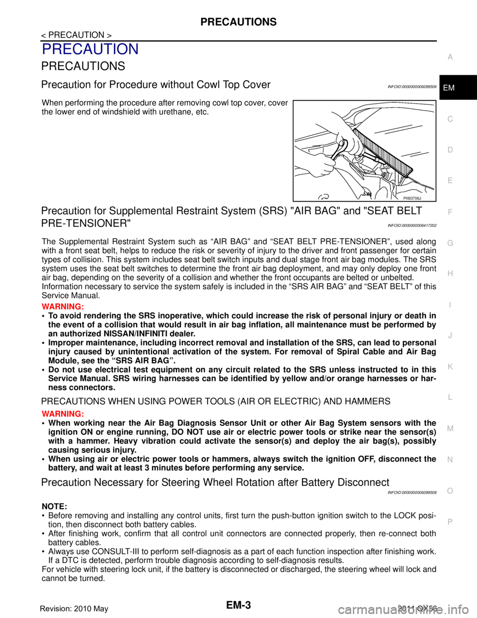
When performing the procedure after removing cowl top cover, cover
the lower end of windshield with urethane, etc.
Precaution for Supplemental Restraint System (SRS) "AIR BAG" and "SEAT BELT
PRE-TENSIONER"
INFOID:0000000006417202
The Supplemental Restraint System such as “A IR BAG” and “SEAT BELT PRE-TENSIONER”, used along
with a front seat belt, helps to reduce the risk or severi ty of injury to the driver and front passenger for certain
types of collision. This system includes seat belt switch inputs and dual stage front air bag modules. The SRS
system uses the seat belt switches to determine the front air bag deployment, and may only deploy one front
air bag, depending on the severity of a collision and whether the front occupants are belted or unbelted.
Information necessary to service the system safely is included in the “SRS AIR BAG” and “SEAT BELT” of this
Service Manual.
WARNING:
• To avoid rendering the SRS inoper ative, which could increase the risk of personal injury or death in
the event of a collision that would result in air ba g inflation, all maintenance must be performed by
an authorized NISSAN/INFINITI dealer.
Improper maintenance, including in correct removal and installation of the SRS, can lead to personal
injury caused by unintentional act ivation of the system. For removal of Spiral Cable and Air Bag
Module, see the “SRS AIR BAG”.
Do not use electrical test equipm ent on any circuit related to the SRS unless instructed to in this
Service Manual. SRS wiring harnesses can be identi fied by yellow and/or orange harnesses or har-
ness connectors.
PRECAUTIONS WHEN USING POWER TOOLS (AIR OR ELECTRIC) AND HAMMERS
WARNING:
When working near the Air Bag Diagnosis Sensor Unit or other Air Bag System sensors with the
ignition ON or engine running, DO NOT use air or electric power tools or strike near the sensor(s)
with a hammer. Heavy vibration could activate the sensor(s) and deploy the air bag(s), possibly
causing serious injury.
When using air or electric power tools or hammers , always switch the ignition OFF, disconnect the
battery, and wait at least 3 minutes before performing any service.
Precaution Necessary for Steering Wh eel Rotation after Battery Disconnect
INFOID:0000000006289508
NOTE:
Before removing and installing any control units, first tu rn the push-button ignition switch to the LOCK posi-
tion, then disconnect both battery cables.
After finishing work, confirm that all control unit connectors are connected properly, then re-connect both
battery cables.
Always use CONSULT-III to perform self-diagnosis as a part of each function inspection after finishing work.
If a DTC is detected, perform trouble diagnos is according to self-diagnosis results.
For vehicle with steering lock unit, if the battery is disconnected or discharged, the steering wheel will lock and
cannot be turned.
PIIB3706J
Revision: 2010 May2011 QX56
Page 2582 of 5598
EM-20
< PERIODIC MAINTENANCE >
DRIVE BELTS
PERIODIC MAINTENANCE
DRIVE BELTS
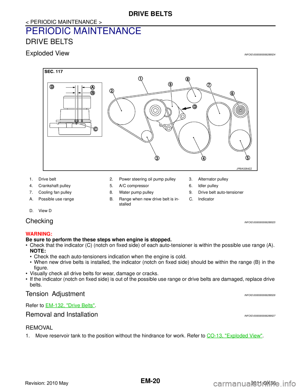
Exploded ViewINFOID:0000000006289524
CheckingINFOID:0000000006289525
WARNING:
Be sure to perform the these steps when engine is stopped.
Check that the indicator (C) (notch on fixed side) of each auto-tensioner is within the possible use range (A).
NOTE:
Check the each auto-tensioners indication when the engine is cold.
When new drive belts is installed, the indicator (notch on fixed side) should be within the range (B) in the\
figure.
Visually check all drive belts for wear, damage or cracks.
If the indicator (notch on fixed side) is out of the possible use range or drive belts are damaged, replace drive
belts.
Tension AdjustmentINFOID:0000000006289526
Refer to EM-132, "Drive Belts".
Removal and InstallationINFOID:0000000006289527
REMOVAL
1. Move reservoir tank to the position without the hindrance for work. Refer to CO-13, "Exploded View".
1. Drive belt 2. Power steering oil pump pulley 3. Alternator pulley
4. Crankshaft pulley 5. A/C compressor 6. Idler pulley
7. Cooling fan pulley 8. Water pump pulley 9. Drive belt auto-tensioner
A. Possible use range B. Range when new drive belt is in-
stalledC. Indicator
D. View D
JPBIA3264ZZ
Revision: 2010 May2011 QX56
Page 2583 of 5598
DRIVE BELTSEM-21
< PERIODIC MAINTENANCE >
C
DE
F
G H
I
J
K L
M A
EM
NP
O
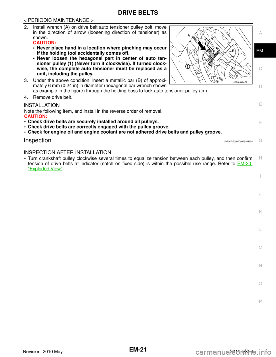
2. Install wrench (A) on drive belt auto tensioner pulley bolt, move
in the direction of arrow (loosening direction of tensioner) as
shown.
CAUTION:
Never place hand in a location where pinching may occurif the holding tool accidentally comes off.
Never loosen the hexagonal part in center of auto ten- sioner pulley (1) (Never turn it clockwise). If turned clock-
wise, the complete auto tensioner must be replaced as a
unit, including the pulley.
3. Under the above condition, insert a metallic bar (B) of approxi- mately 6 mm (0.24 in) in diameter (hexagonal bar wrench shown
as example in the figure) through the holding boss to lock auto tensioner pulley arm.
4. Remove drive belt.
INSTALLATION
Note the following item, and install in the reverse order of removal.
CAUTION:
Check drive belts are securely installed around all pulleys.
Check drive belts are correctly engaged with the pulley groove.
Check for engine oil and engine coolant ar e not adhered drive belts and pulley groove.
InspectionINFOID:0000000006289528
INSPECTION AFTER INSTALLATION
Turn crankshaft pulley clockwise several times to equalize tension between each pulley, and then confirm
tension of drive belts at indicator (notch on fixed side) is within the possible use range. Refer to EM-20,
"Exploded View".
JPBIA3484ZZ
Revision: 2010 May2011 QX56
Page 2584 of 5598
EM-22
< PERIODIC MAINTENANCE >
AIR CLEANER FILTER
AIR CLEANER FILTER
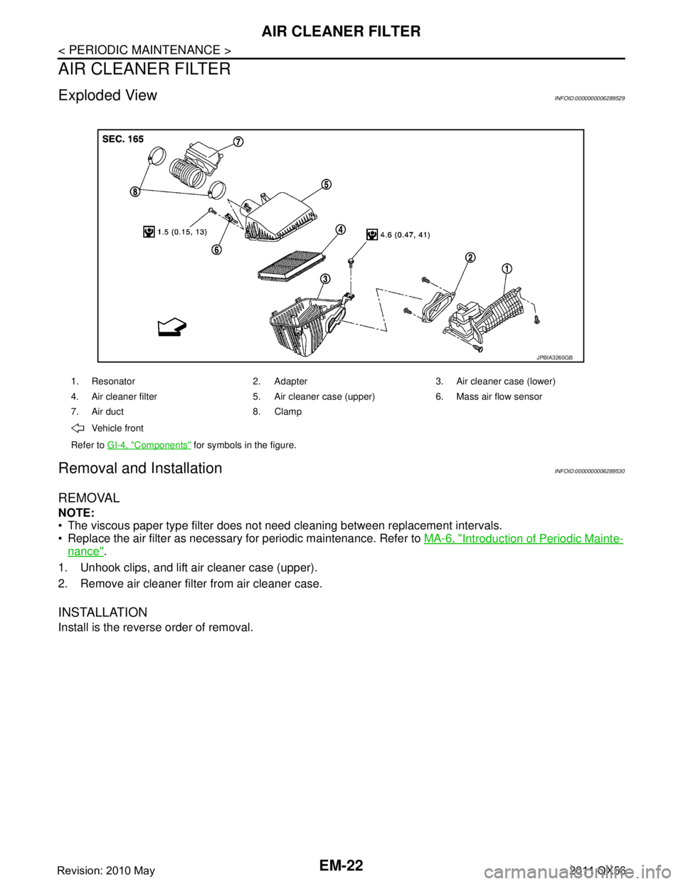
Exploded ViewINFOID:0000000006289529
Removal and InstallationINFOID:0000000006289530
REMOVAL
NOTE:
The viscous paper type filter does not need cleaning between replacement intervals.
Replace the air filter as necessary for periodic maintenance. Refer to MA-6, "
Introduction of Periodic Mainte-
nance".
1. Unhook clips, and lift air cleaner case (upper).
2. Remove air cleaner filter from air cleaner case.
INSTALLATION
Install is the reverse order of removal.
1. Resonator 2. Adapter 3. Air cleaner case (lower)
4. Air cleaner filter 5. Air cleaner case (upper) 6. Mass air flow sensor
7. Air duct 8. Clamp
Vehicle front
Refer to GI-4, "
Components" for symbols in the figure.
JPBIA3260GB
Revision: 2010 May2011 QX56
Page 2585 of 5598
SPARK PLUGEM-23
< PERIODIC MAINTENANCE >
C
DE
F
G H
I
J
K L
M A
EM
NP
O
SPARK PLUG
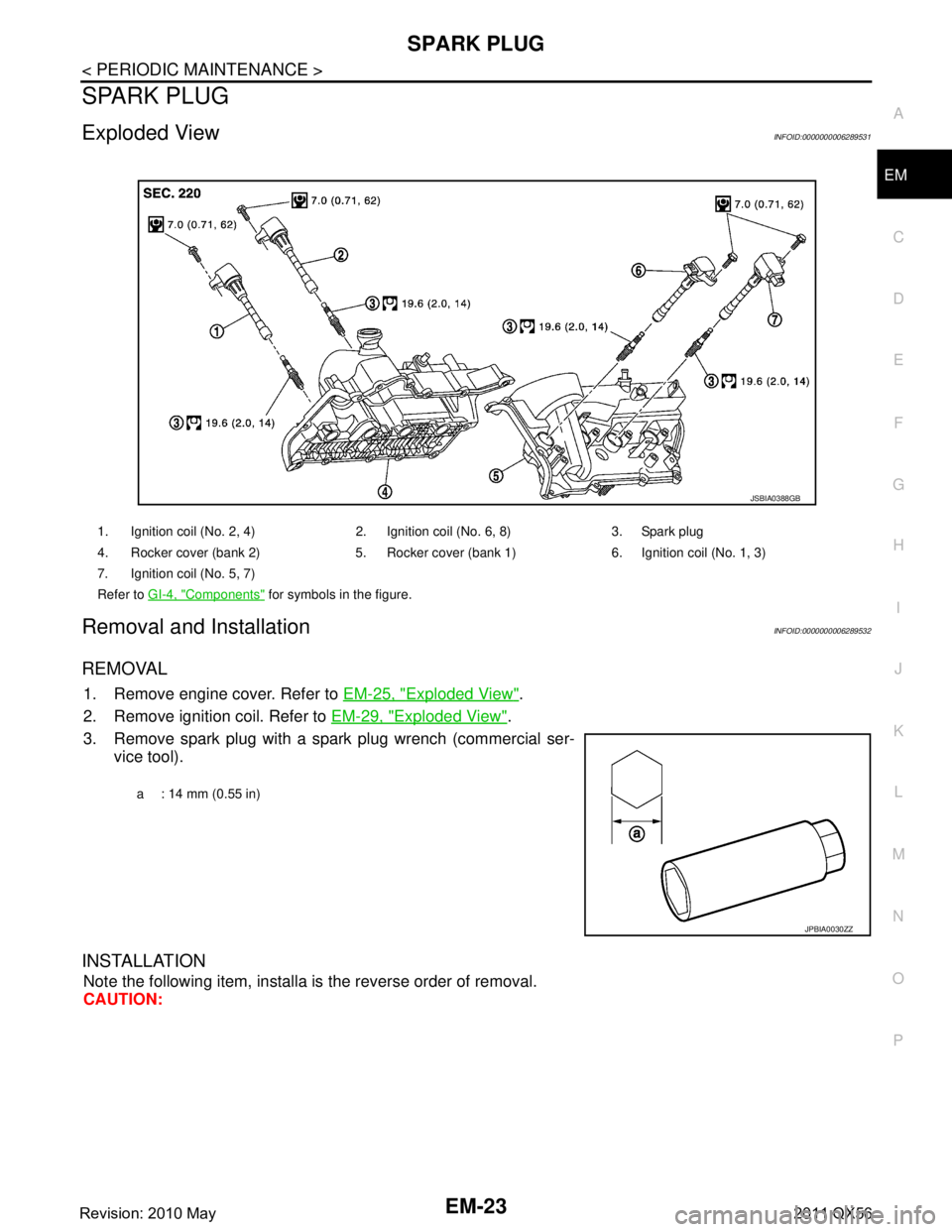
Exploded ViewINFOID:0000000006289531
Removal and InstallationINFOID:0000000006289532
REMOVAL
1. Remove engine cover. Refer to
EM-25, "Exploded View".
2. Remove ignition coil. Refer to EM-29, "
Exploded View".
3. Remove spark plug with a spark plug wrench (commercial ser- vice tool).
INSTALLATION
Note the following item, installa is the reverse order of removal.
CAUTION:
1. Ignition coil (No. 2, 4) 2. Ignition coil (No. 6, 8) 3. Spark plug
4. Rocker cover (bank 2) 5. Rocker cover (bank 1) 6. Ignition coil (No. 1, 3)
7. Ignition coil (No. 5, 7)
Refer to GI-4, "
Components" for symbols in the figure.
JSBIA0388GB
a : 14 mm (0.55 in)
JPBIA0030ZZ
Revision: 2010 May2011 QX56