2011 INFINITI QX56 maintenance
[x] Cancel search: maintenancePage 5263 of 5598
![INFINITI QX56 2011 Factory Service Manual
A/T FLUIDTM-175
< PERIODIC MAINTENANCE > [7AT: RE7R01B]
C
EF
G H
I
J
K L
M A
B
TM
N
O P
PERIODIC MAINTENANCE
A/T FLUID
InspectionINFOID:0000000006288673
FLUID LEAKAGE
Check transaxle surrounding ar INFINITI QX56 2011 Factory Service Manual
A/T FLUIDTM-175
< PERIODIC MAINTENANCE > [7AT: RE7R01B]
C
EF
G H
I
J
K L
M A
B
TM
N
O P
PERIODIC MAINTENANCE
A/T FLUID
InspectionINFOID:0000000006288673
FLUID LEAKAGE
Check transaxle surrounding ar](/manual-img/42/57033/w960_57033-5262.png)
A/T FLUIDTM-175
< PERIODIC MAINTENANCE > [7AT: RE7R01B]
C
EF
G H
I
J
K L
M A
B
TM
N
O P
PERIODIC MAINTENANCE
A/T FLUID
InspectionINFOID:0000000006288673
FLUID LEAKAGE
Check transaxle surrounding area (oil seal and plug etc.) for fluid leakage.
If anything is found, repair or replace damaged parts and adjust A/
T fluid level. Refer to TM-95, "
Adjustment".
JSDIA1912ZZ
Revision: 2010 May2011 QX56
Page 5389 of 5598
PRECAUTIONSVTL-3
< PRECAUTION >
C
DE
F
G H
J
K L
M A
B
VTL
N
O P
PRECAUTION
PRECAUTIONS
Precaution for Supplemental Restraint System (SRS) "AIR BAG" and "SEAT BELT
PRE-TENSIONER"
INFOID:0000000006376373
The Supplemental Restraint System such as “A IR BAG” and “SEAT BELT PRE-TENSIONER”, used along
with a front seat belt, helps to reduce the risk or severi ty of injury to the driver and front passenger for certain
types of collision. This system includes seat belt switch inputs and dual stage front air bag modules. The SRS
system uses the seat belt switches to determine the front air bag deployment, and may only deploy one front
air bag, depending on the severity of a collision and whether the front occupants are belted or unbelted.
Information necessary to service the system safely is included in the “SRS AIR BAG” and “SEAT BELT” of this
Service Manual.
WARNING:
• To avoid rendering the SRS inoper ative, which could increase the risk of personal injury or death in
the event of a collision that would result in air ba g inflation, all maintenance must be performed by
an authorized NISSAN/INFINITI dealer.
Improper maintenance, including in correct removal and installation of the SRS, can lead to personal
injury caused by unintentional act ivation of the system. For removal of Spiral Cable and Air Bag
Module, see the “SRS AIR BAG”.
Do not use electrical test equipm ent on any circuit related to the SRS unless instructed to in this
Service Manual. SRS wiring harnesses can be identi fied by yellow and/or orange harnesses or har-
ness connectors.
PRECAUTIONS WHEN USING POWER TOOLS (AIR OR ELECTRIC) AND HAMMERS
WARNING:
When working near the Air Bag Diagnosis Sensor Unit or other Air Bag System sensors with the
ignition ON or engine running, DO NOT use air or electric power tools or strike near the sensor(s)
with a hammer. Heavy vibration could activate the sensor(s) and deploy the air bag(s), possibly
causing serious injury.
When using air or electric power tools or hammers , always switch the ignition OFF, disconnect the
battery, and wait at least 3 minutes before performing any service.
Precaution Necessary for Steering Wh eel Rotation after Battery Disconnect
INFOID:0000000006376453
NOTE:
Before removing and installing any control units, first tu rn the push-button ignition switch to the LOCK posi-
tion, then disconnect both battery cables.
After finishing work, confirm that all control unit connectors are connected properly, then re-connect both
battery cables.
Always use CONSULT-III to perform self-diagnosis as a part of each function inspection after finishing work.
If a DTC is detected, perform trouble diagnos is according to self-diagnosis results.
For vehicle with steering lock unit, if the battery is disconnected or discharged, the steering wheel will lock and
cannot be turned.
If turning the steering wheel is required with the batte ry disconnected or discharged, follow the operation pro-
cedure below before starting the repair operation.
OPERATION PROCEDURE
1. Connect both battery cables. NOTE:
Supply power using jumper cables if battery is discharged.
2. Turn the push-button ignition switch to ACC position. (At this time, the steering lock will be released.)
3. Disconnect both battery cables. The steering lock wil l remain released with both battery cables discon-
nected and the steering wheel can be turned.
4. Perform the necessary repair operation.
Revision: 2010 May2011 QX56
Page 5407 of 5598
WCS
PRECAUTIONSWCS-3
< PRECAUTION >
C
DE
F
G H
I
J
K L
M B A
O P
PRECAUTION
PRECAUTIONS
Precaution for Supplemental Restraint System (SRS) "AIR BAG" and "SEAT BELT
PRE-TENSIONER"
INFOID:0000000006369725
The Supplemental Restraint System such as “A IR BAG” and “SEAT BELT PRE-TENSIONER”, used along
with a front seat belt, helps to reduce the risk or severi ty of injury to the driver and front passenger for certain
types of collision. This system includes seat belt switch inputs and dual stage front air bag modules. The SRS
system uses the seat belt switches to determine the front air bag deployment, and may only deploy one front
air bag, depending on the severity of a collision and whether the front occupants are belted or unbelted.
Information necessary to service the system safely is included in the “SRS AIR BAG” and “SEAT BELT” of this
Service Manual.
WARNING:
• To avoid rendering the SRS inoper ative, which could increase the risk of personal injury or death in
the event of a collision that would result in air ba g inflation, all maintenance must be performed by
an authorized NISSAN/INFINITI dealer.
Improper maintenance, including in correct removal and installation of the SRS, can lead to personal
injury caused by unintentional act ivation of the system. For removal of Spiral Cable and Air Bag
Module, see the “SRS AIR BAG”.
Do not use electrical test equipm ent on any circuit related to the SRS unless instructed to in this
Service Manual. SRS wiring harnesses can be identi fied by yellow and/or orange harnesses or har-
ness connectors.
PRECAUTIONS WHEN USING POWER TOOLS (AIR OR ELECTRIC) AND HAMMERS
WARNING:
When working near the Air Bag Diagnosis Sensor Unit or other Air Bag System sensors with the
ignition ON or engine running, DO NOT use air or electric power tools or strike near the sensor(s)
with a hammer. Heavy vibration could activate the sensor(s) and deploy the air bag(s), possibly
causing serious injury.
When using air or electric power tools or hammers , always switch the ignition OFF, disconnect the
battery, and wait at least 3 minutes before performing any service.
Revision: 2010 May2011 QX56
Page 5452 of 5598

WT-2
DTC Logic ...............................................................39
Diagnosis Procedure ..............................................39
C1729 VEHICLE SPEED SIGNAL ....................41
DTC Logic ............................................................ ...41
Diagnosis Procedure ..............................................41
C1750, C1751, C1752, C1753 RECEIVER ........42
DTC Logic ............................................................ ...42
Diagnosis Procedure ..............................................42
C1754 LOW TIRE PRESSURE WARNING
CONTROL UNIT ................................................
45
DTC Logic ............................................................ ...45
Diagnosis Procedure ..............................................45
C1755, C1756, C1757, C1758 POOR RE-
CEIVING CONDITIONS .....................................
47
DTC Logic ............................................................ ...47
Diagnosis Procedure ..............................................47
U1000 CAN COMM CIRCUIT ............................49
Description ........................................................... ...49
DTC Logic ...............................................................49
Diagnosis Procedure ..............................................49
U1010 CONTROL UNIT (CAN) .........................50
Description ........................................................... ...50
DTC Logic ...............................................................50
Diagnosis Procedure ..............................................50
POWER SUPPLY AND GROUND CIRCUIT .....51
Diagnosis Procedure ........................................... ...51
LOW TIRE PRESSURE WARNING LAMP .......52
Component Function Check ................................ ...52
Diagnosis Procedure ..............................................52
SYMPTOM DIAGNOSIS .............................53
TPMS SYMPTOMS ......................................... ...53
Symptom Table ................................................... ...53
LOW TIRE PRESSURE WARNING LAMP
DOES NOT TURN ON .......................................
56
Description ........................................................... ...56
Diagnosis Procedure ..............................................56
LOW TIRE PRESSURE WARNING LAMP
DOES NOT TURN OFF .....................................
57
Description ........................................................... ...57
Diagnosis Procedure ..............................................57
LOW TIRE PRESSURE WARNING LAMP
BLINKS ..............................................................
58
Description ........................................................... ...58
Diagnosis Procedure ............................................ ...58
TIRE INFLATION INDICATOR DOES NOT
ACTIVATE .........................................................
59
Description ........................................................... ...59
Diagnosis Procedure ...............................................59
ID REGISTRATION CANNOT BE COMPLET-
ED ......................................................................
60
Description ........................................................... ...60
Diagnosis Procedure ..............................................60
NOISE, VIBRATION AND HARSHNESS
(NVH) TROUBLESHOOTING ............................
61
NVH Troubleshooting Chart ................................. ...61
PERIODIC MAINTENANCE .......................62
ROAD WHEEL ................................................ ...62
Adjustment ........................................................... ...62
Tire Rotation ...........................................................63
REMOVAL AND INSTALLATION ..............64
ROAD WHEEL TIRE ASSEMBLY ................. ...64
Exploded View ..................................................... ...64
Removal and Installation .........................................64
Inspection ................................................................64
LOW TIRE PRESSURE WARNING CON-
TROL UNIT ........................................................
65
Exploded View ..................................................... ...65
Removal and Installation .........................................65
TRANSMITTER .................................................66
Exploded View ..................................................... ...66
Removal and Installation .........................................66
TIRE PRESSURE RECEIVER ...........................68
Exploded View ..................................................... ...68
FRONT TIRE PRESSURE RECEIVER .................. ...68
FRONT TIRE PRESSURE RECEIVER : Removal
and Installation ........................................................
68
REAR TIRE PRESSURE RECEIVER .......................68
REAR TIRE PRESSURE RECEIVER : Removal
and Installation ..................................................... ...
68
SERVICE DATA AND SPECIFICATIONS
(SDS) .......... ................................................
69
SERVICE DATA AND SPECIFICATIONS
(SDS) .............................................................. ...
69
Road Wheel ......................................................... ...69
Tire Air Pressure .....................................................69
Revision: 2010 May2011 QX56
Page 5453 of 5598
PRECAUTIONSWT-3
< PRECAUTION >
C
DF
G H
I
J
K L
M A
B
WT
N
O P
PRECAUTION
PRECAUTIONS
Precaution for Supplemental Restraint System (SRS) "AIR BAG" and "SEAT BELT
PRE-TENSIONER"
INFOID:0000000006256474
The Supplemental Restraint System such as “A IR BAG” and “SEAT BELT PRE-TENSIONER”, used along
with a front seat belt, helps to reduce the risk or severi ty of injury to the driver and front passenger for certain
types of collision. This system includes seat belt switch inputs and dual stage front air bag modules. The SRS
system uses the seat belt switches to determine the front air bag deployment, and may only deploy one front
air bag, depending on the severity of a collision and whether the front occupants are belted or unbelted.
Information necessary to service the system safely is included in the “SRS AIR BAG” and “SEAT BELT” of this
Service Manual.
WARNING:
• To avoid rendering the SRS inoper ative, which could increase the risk of personal injury or death in
the event of a collision that would result in air ba g inflation, all maintenance must be performed by
an authorized NISSAN/INFINITI dealer.
Improper maintenance, including in correct removal and installation of the SRS, can lead to personal
injury caused by unintentional act ivation of the system. For removal of Spiral Cable and Air Bag
Module, see the “SRS AIR BAG”.
Do not use electrical test equipm ent on any circuit related to the SRS unless instructed to in this
Service Manual. SRS wiring harnesses can be identi fied by yellow and/or orange harnesses or har-
ness connectors.
PRECAUTIONS WHEN USING POWER TOOLS (AIR OR ELECTRIC) AND HAMMERS
WARNING:
When working near the Air Bag Diagnosis Sensor Unit or other Air Bag System sensors with the
ignition ON or engine running, DO NOT use air or electric power tools or strike near the sensor(s)
with a hammer. Heavy vibration could activate the sensor(s) and deploy the air bag(s), possibly
causing serious injury.
When using air or electric power tools or hammers , always switch the ignition OFF, disconnect the
battery, and wait at least 3 minutes before performing any service.
Precaution Necessary for Steering Wh eel Rotation after Battery Disconnect
INFOID:0000000006256475
NOTE:
Before removing and installing any control units, first tu rn the push-button ignition switch to the LOCK posi-
tion, then disconnect both battery cables.
After finishing work, confirm that all control unit connectors are connected properly, then re-connect both
battery cables.
Always use CONSULT-III to perform self-diagnosis as a part of each function inspection after finishing work.
If a DTC is detected, perform trouble diagnos is according to self-diagnosis results.
For vehicle with steering lock unit, if the battery is disconnected or discharged, the steering wheel will lock and
cannot be turned.
If turning the steering wheel is required with the batte ry disconnected or discharged, follow the operation pro-
cedure below before starting the repair operation.
OPERATION PROCEDURE
1. Connect both battery cables. NOTE:
Supply power using jumper cables if battery is discharged.
2. Turn the push-button ignition switch to ACC position. (At this time, the steering lock will be released.)
3. Disconnect both battery cables. The steering lock wil l remain released with both battery cables discon-
nected and the steering wheel can be turned.
4. Perform the necessary repair operation.
Revision: 2010 May2011 QX56
Page 5512 of 5598
WT-62
< PERIODIC MAINTENANCE >
ROAD WHEEL
PERIODIC MAINTENANCE
ROAD WHEEL
AdjustmentINFOID:0000000006225545
BALANCING WHEELS (BONDING WEIGHT TYPE)
Preparation Before Adjustment
Using releasing agent, remove double-faced adhesive tape from the road wheel.
CAUTION:
Be careful not to scratch the road wheel during removal.
After removing double-faced adhesive tape, wi pe clean traces of releasing agent from the road
wheel.
Wheel Balance Adjustment
If a tire balance machine has adhesion balance weight m ode settings and drive-in weight mode setting, select
and adjust a drive-in weight mode suitable for road wheels.
1. Set road wheel on tire balance machine using the center hole as a guide. Start the tire balance machine.
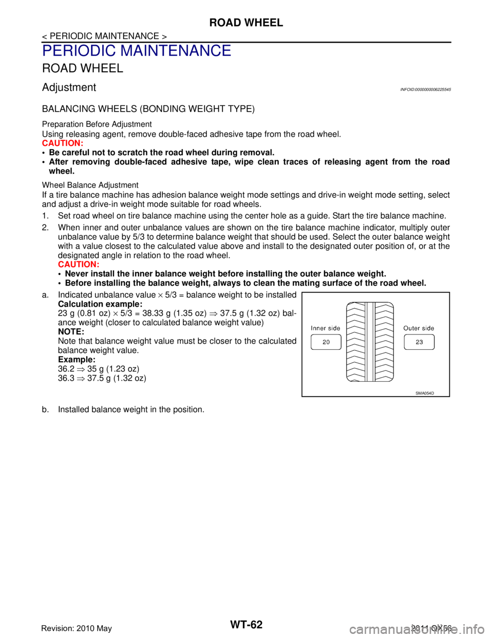
2. When inner and outer unbalance values are shown on the tire balance machine indicator, multiply outer unbalance value by 5/3 to determine balance weight t hat should be used. Select the outer balance weight
with a value closest to the calculated value above and in stall to the designated outer position of, or at the
designated angle in relation to the road wheel.
CAUTION:
Never install the inner balance weight be fore installing the outer balance weight.
Before installing the balance weight, always to clean the mating surface of the road wheel.
a. Indicated unbalance value × 5/3 = balance weight to be installed
Calculation example:
23 g (0.81 oz) × 5/3 = 38.33 g (1.35 oz) ⇒ 37.5 g (1.32 oz) bal-
ance weight (closer to calculated balance weight value)
NOTE:
Note that balance weight value must be closer to the calculated
balance weight value.
Example:
36.2 ⇒ 35 g (1.23 oz)
36.3 ⇒ 37.5 g (1.32 oz)
b. Installed balance weight in the position.
SMA054D
Revision: 2010 May2011 QX56
Page 5513 of 5598
ROAD WHEELWT-63
< PERIODIC MAINTENANCE >
C
DF
G H
I
J
K L
M A
B
WT
N
O P
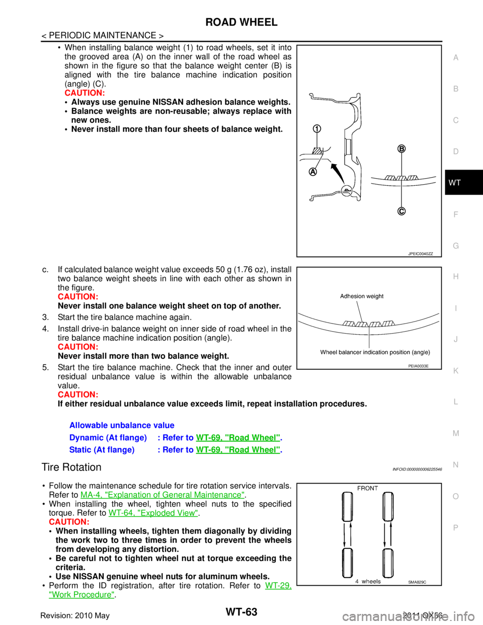
When installing balance weight (1) to road wheels, set it into the grooved area (A) on the inner wall of the road wheel as
shown in the figure so that the balance weight center (B) is
aligned with the tire balance machine indication position
(angle) (C).
CAUTION:
Always use genuine NISSAN ad hesion balance weights.
Balance weights are non-re usable; always replace with
new ones.
Never install more than four sheets of balance weight.
c. If calculated balance weight value exceeds 50 g (1.76 oz), install two balance weight sheets in line with each other as shown in
the figure.
CAUTION:
Never install one balance weight sheet on top of another.
3. Start the tire balance machine again.
4. Install drive-in balance weight on inner side of road wheel in the tire balance machine indication position (angle).
CAUTION:
Never install more than two balance weight.
5. Start the tire balance machine. Check that the inner and outer residual unbalance value is within the allowable unbalance
value.
CAUTION:
If either residual unbalan ce value exceeds limit, repeat installation procedures.
Tire RotationINFOID:0000000006225546
Follow the maintenance schedule for tire rotation service intervals.
Refer to MA-4, "
Explanation of General Maintenance".
When installing the wheel, tighten wheel nuts to the specified torque. Refer to WT-64, "
Exploded View".
CAUTION:
When installing wheels, tighte n them diagonally by dividing
the work two to three times in order to prevent the wheels
from developing any distortion.
Be careful not to tighten wh eel nut at torque exceeding the
criteria.
Use NISSAN genuine wheel nuts for aluminum wheels.
Perform the ID registration, after tire rotation. Refer to WT-29,
"Work Procedure".
JPEIC0040ZZ
Allowable unbalance value
Dynamic (At flange) : Refer to WT-69, "
Road Wheel".
Static (At flange) : Refer to WT-69, "
Road Wheel".
PEIA0033E
SMA829C
Revision: 2010 May2011 QX56
Page 5522 of 5598
PRECAUTIONSWW-3
< PRECAUTION >
C
DE
F
G H
I
J
K
M A
B
WW
N
O P
PRECAUTION
PRECAUTIONS
Precaution for Supplemental Restraint System (SRS) "AIR BAG" and "SEAT BELT
PRE-TENSIONER"
INFOID:0000000006349780
The Supplemental Restraint System such as “A IR BAG” and “SEAT BELT PRE-TENSIONER”, used along
with a front seat belt, helps to reduce the risk or severi ty of injury to the driver and front passenger for certain
types of collision. This system includes seat belt switch inputs and dual stage front air bag modules. The SRS
system uses the seat belt switches to determine the front air bag deployment, and may only deploy one front
air bag, depending on the severity of a collision and whether the front occupants are belted or unbelted.
Information necessary to service the system safely is included in the “SRS AIR BAG” and “SEAT BELT” of this
Service Manual.
WARNING:
• To avoid rendering the SRS inoper ative, which could increase the risk of personal injury or death in
the event of a collision that would result in air ba g inflation, all maintenance must be performed by
an authorized NISSAN/INFINITI dealer.
Improper maintenance, including in correct removal and installation of the SRS, can lead to personal
injury caused by unintentional act ivation of the system. For removal of Spiral Cable and Air Bag
Module, see the “SRS AIR BAG”.
Do not use electrical test equipm ent on any circuit related to the SRS unless instructed to in this
Service Manual. SRS wiring harnesses can be identi fied by yellow and/or orange harnesses or har-
ness connectors.
PRECAUTIONS WHEN USING POWER TOOLS (AIR OR ELECTRIC) AND HAMMERS
WARNING:
When working near the Air Bag Diagnosis Sensor Unit or other Air Bag System sensors with the
ignition ON or engine running, DO NOT use air or electric power tools or strike near the sensor(s)
with a hammer. Heavy vibration could activate the sensor(s) and deploy the air bag(s), possibly
causing serious injury.
When using air or electric power tools or hammers , always switch the ignition OFF, disconnect the
battery, and wait at least 3 minutes before performing any service.
Precaution Necessary for Steering Wh eel Rotation after Battery Disconnect
INFOID:0000000006300446
NOTE:
Before removing and installing any control units, first tu rn the push-button ignition switch to the LOCK posi-
tion, then disconnect both battery cables.
After finishing work, confirm that all control unit connectors are connected properly, then re-connect both
battery cables.
Always use CONSULT-III to perform self-diagnosis as a part of each function inspection after finishing work.
If a DTC is detected, perform trouble diagnos is according to self-diagnosis results.
For vehicle with steering lock unit, if the battery is disconnected or discharged, the steering wheel will lock and
cannot be turned.
If turning the steering wheel is required with the batte ry disconnected or discharged, follow the operation pro-
cedure below before starting the repair operation.
OPERATION PROCEDURE
1. Connect both battery cables. NOTE:
Supply power using jumper cables if battery is discharged.
2. Turn the push-button ignition switch to ACC position. (At this time, the steering lock will be released.)
3. Disconnect both battery cables. The steering lock wil l remain released with both battery cables discon-
nected and the steering wheel can be turned.
4. Perform the necessary repair operation.
Revision: 2010 May2011 QX56