2011 INFINITI QX56 maintenance
[x] Cancel search: maintenancePage 4990 of 5598

PRECAUTIONSST-3
< PRECAUTION >
C
DE
F
H I
J
K L
M A
B
ST
N
O P
PRECAUTION
PRECAUTIONS
Precaution for Supplemental Restraint System (SRS) "AIR BAG" and "SEAT BELT
PRE-TENSIONER"
INFOID:0000000006272045
The Supplemental Restraint System such as “A IR BAG” and “SEAT BELT PRE-TENSIONER”, used along
with a front seat belt, helps to reduce the risk or severi ty of injury to the driver and front passenger for certain
types of collision. This system includes seat belt switch inputs and dual stage front air bag modules. The SRS
system uses the seat belt switches to determine the front air bag deployment, and may only deploy one front
air bag, depending on the severity of a collision and whether the front occupants are belted or unbelted.
Information necessary to service the system safely is included in the “SRS AIR BAG” and “SEAT BELT” of this
Service Manual.
WARNING:
• To avoid rendering the SRS inoper ative, which could increase the risk of personal injury or death in
the event of a collision that would result in air ba g inflation, all maintenance must be performed by
an authorized NISSAN/INFINITI dealer.
Improper maintenance, including in correct removal and installation of the SRS, can lead to personal
injury caused by unintentional act ivation of the system. For removal of Spiral Cable and Air Bag
Module, see the “SRS AIR BAG”.
Do not use electrical test equipm ent on any circuit related to the SRS unless instructed to in this
Service Manual. SRS wiring harnesses can be identi fied by yellow and/or orange harnesses or har-
ness connectors.
PRECAUTIONS WHEN USING POWER TOOLS (AIR OR ELECTRIC) AND HAMMERS
WARNING:
When working near the Air Bag Diagnosis Sensor Unit or other Air Bag System sensors with the
ignition ON or engine running, DO NOT use air or electric power tools or strike near the sensor(s)
with a hammer. Heavy vibration could activate the sensor(s) and deploy the air bag(s), possibly
causing serious injury.
When using air or electric power tools or hammers , always switch the ignition OFF, disconnect the
battery, and wait at least 3 minutes before performing any service.
Precaution Necessary for Steering Wh eel Rotation after Battery Disconnect
INFOID:0000000006272046
NOTE:
Before removing and installing any control units, first tu rn the push-button ignition switch to the LOCK posi-
tion, then disconnect both battery cables.
After finishing work, confirm that all control unit connectors are connected properly, then re-connect both
battery cables.
Always use CONSULT-III to perform self-diagnosis as a part of each function inspection after finishing work.
If a DTC is detected, perform trouble diagnos is according to self-diagnosis results.
For vehicle with steering lock unit, if the battery is disconnected or discharged, the steering wheel will lock and
cannot be turned.
If turning the steering wheel is required with the batte ry disconnected or discharged, follow the operation pro-
cedure below before starting the repair operation.
OPERATION PROCEDURE
1. Connect both battery cables. NOTE:
Supply power using jumper cables if battery is discharged.
2. Turn the push-button ignition switch to ACC position. (At this time, the steering lock will be released.)
3. Disconnect both battery cables. The steering lock wil l remain released with both battery cables discon-
nected and the steering wheel can be turned.
4. Perform the necessary repair operation.
Revision: 2010 May2011 QX56
Page 5017 of 5598

ST-30
< PERIODIC MAINTENANCE >
POWER STEERING FLUID
PERIODIC MAINTENANCE
POWER STEERING FLUID
InspectionINFOID:0000000006225597
FLUID LEVEL
1. Check fluid level with engine stopped.
2. Ensure that fluid level is between MIN and MAX.
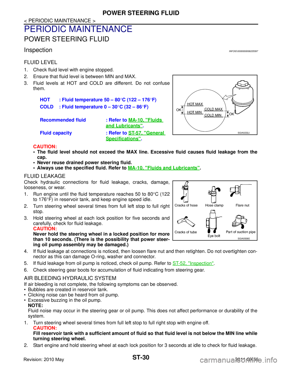
3. Fluid levels at HOT and COLD are different. Do not confuse
them.
CAUTION:
The fluid level should not exceed the MAX line. Excessive flui d causes fluid leakage from the
cap.
Never reuse drained power steering fluid.
Always use the specified fluid. Refer to MA-10, "
Fluids and Lubricants".
FLUID LEAKAGE
Check hydraulic connections for fluid leakage, cracks, damage,
looseness, or wear.
1. Run engine until the fluid temperature reaches 50 to 80 °C (122
to 176 °F) in reservoir tank, and keep engine speed idle.
2. Turn steering wheel several times from full left stop to full right stop.
3. Hold steering wheel at each lock position for five seconds and carefully, check for fluid leakage.
CAUTION:
Never hold the steering wheel in a locked position for more
than 10 seconds. (There is the possibility that power steer-
ing oil pump assembly may be damaged.)
4. If fluid leakage at connections is noticed, then loos en flare nut and then retighten. Do not overtighten con-
nector as this can damage O-ring, washer and connector.
5. If fluid leakage from oil pump is noticed, check oil pump. Refer to ST-52, "
Inspection".
6. Check steering gear boots for accumulation of fluid indicating from steering gear.
AIR BLEEDING HYDRAULIC SYSTEM
If air bleeding is not complete, the following symptoms can be observed.
Bubbles are created in reservoir tank.
Clicking noise can be heard from oil pump.
Excessive buzzing in the oil pump. NOTE:
Fluid noise may occur in the steering gear or oil pump. This does not affect performance or durability of the
system.
1. Turn steering wheel several times from full left stop to full right stop with engine off. CAUTION:
Fill reservoir tank with a sufficien t amount of fluid so that fluid level is not below the MIN line while
turning steering wheel.
2. Start engine and hold steering wheel at each lock position for 3 seconds at idle to check for fluid leakage.
HOT : Fluid temperature 50 – 80
°C (122 – 176 °F)
COLD : Fluid temperature 0 – 30 °C (32 – 86 °F)
Recommended fluid : Refer to MA-10, "
Fluids
and Lubricants".
Fluid capacity : Refer to ST-57, "
General
Specifications".
SGIA0232J
SGIA0506E
Revision: 2010 May2011 QX56
Page 5018 of 5598

POWER STEERING FLUIDST-31
< PERIODIC MAINTENANCE >
C
DE
F
H I
J
K L
M A
B
ST
N
O P
3. Repeat step 2 above several times at approximately 3 seconds intervals. CAUTION:
Never hold the steering wheel in a locked positio n for more than 10 seconds. (There is the possi-
bility that oil pump may be damaged.)
4. Check fluid for bubbles and while contamination.
5. Stop engine if bubbles and white contamination do not drain out. Perform step 2 and 3 above after waiting
until bubbles and white contamination drain out.
6. Stop the engine, and then check fluid level.
Revision: 2010 May2011 QX56
Page 5019 of 5598

ST-32
< PERIODIC MAINTENANCE >
STEERING WHEEL
STEERING WHEEL
InspectionINFOID:0000000006225598
STEERING WHEEL AXIAL END PLAY
1. Check installation conditions of steering gear assembly, front suspension assembly, axle and steering col-
umn assembly.
2. Check if movement exists when steering wheel is moved up and down, to the left and right and to the axial direction.
3. Check the following items when steering w heel axial end play is out of the standard.
Check the steering column assembly mounting condition. Refer to ST-34, "
Exploded View".
Check steering gear assembly mounting condition for looseness. Refer to ST-41, "
Exploded View".
STEERING WHEEL PLAY
1. Turn steering wheel so that front wheels come to the straight-ahead position.
2. Start engine and lightly turn steering wheel to the left and right until front wheels start to move.
3. Measure steering wheel movement on the outer circumference.
4. Check the following items when steeri ng wheel play is out of the standard.
Check backlash for each joint of steering column assembly.
Check installation condition of steering gear assembly. Steering wheel axial end play : Refer to
ST-57, "
Steering Wheel Axial End Play and Play".
Steering wheel play : Refer to ST-57, "
Steering Wheel Axial End Play and Play".
Revision: 2010 May2011 QX56
Page 5047 of 5598

STC-2
< PRECAUTION >
PRECAUTIONS
PRECAUTION
PRECAUTIONS
Precaution for Supplemental Restraint System (SRS) "AIR BAG" and "SEAT BELT
PRE-TENSIONER"
INFOID:0000000006303358
The Supplemental Restraint System such as “A IR BAG” and “SEAT BELT PRE-TENSIONER”, used along
with a front seat belt, helps to reduce the risk or severi ty of injury to the driver and front passenger for certain
types of collision. This system includes seat belt switch inputs and dual stage front air bag modules. The SRS
system uses the seat belt switches to determine the front air bag deployment, and may only deploy one front
air bag, depending on the severity of a collision and w hether the front occupants are belted or unbelted.
Information necessary to service the system safely is included in the “SRS AIR BAG” and “SEAT BELT” of this
Service Manual.
WARNING:
• To avoid rendering the SRS inopera tive, which could increase the risk of personal injury or death in
the event of a collision that would result in air bag inflation, all maintenance must be performed by
an authorized NISS AN/INFINITI dealer.
Improper maintenance, including in correct removal and installation of the SRS, can lead to personal
injury caused by unintent ional activation of the system. For re moval of Spiral Cable and Air Bag
Module, see the “SRS AIR BAG”.
Do not use electrical test equipmen t on any circuit related to the SRS unless instructed to in this
Service Manual. SRS wiring harnesses can be identi fied by yellow and/or orange harnesses or har-
ness connectors.
PRECAUTIONS WHEN USING POWER TOOLS (AIR OR ELECTRIC) AND HAMMERS
WARNING:
When working near the Air Bag Diagnosis Sensor Unit or other Air Bag System sensors with the ignition ON or engine running, DO NOT use air or electric power tools or strike near the sensor(s)
with a hammer. Heavy vibration could activate the sensor(s) and deploy the air bag(s), possibly
causing serious injury.
When using air or electric power tools or hammers , always switch the ignition OFF, disconnect the
battery, and wait at least 3 minu tes before performing any service.
Precaution Necessary for Steering W heel Rotation after Battery Disconnect
INFOID:0000000006303360
NOTE:
Before removing and installing any control units, first tu rn the push-button ignition switch to the LOCK posi-
tion, then disconnect bot h battery cables.
After finishing work, confirm that all control unit connectors are connected properly, then re-connect both
battery cables.
Always use CONSULT-III to perform self-diagnosis as a part of each function inspection after finishing work.
If a DTC is detected, perform trouble diagnos is according to self-diagnosis results.
For vehicle with steering lock unit, if the battery is disconnected or discharged, the steering wheel will lock and
cannot be turned.
If turning the steering wheel is required with the bat tery disconnected or discharged, follow the operation pro-
cedure below before starting the repair operation.
OPERATION PROCEDURE
1. Connect both battery cables. NOTE:
Supply power using jumper cables if battery is discharged.
2. Turn the push-button ignition switch to ACC position. (At this time, the steering lock will be released.)
3. Disconnect both battery cables. The steering lock wi ll remain released with both battery cables discon-
nected and the steering wheel can be turned.
4. Perform the necessary repair operation.
Revision: 2010 May2011 QX56
Page 5070 of 5598

STR-2
< PRECAUTION >
PRECAUTIONS
PRECAUTION
PRECAUTIONS
Precaution for Supplemental Restraint System (SRS) "AIR BAG" and "SEAT BELT
PRE-TENSIONER"
INFOID:0000000006275515
The Supplemental Restraint System such as “A IR BAG” and “SEAT BELT PRE-TENSIONER”, used along
with a front seat belt, helps to reduce the risk or severi ty of injury to the driver and front passenger for certain
types of collision. This system includes seat belt switch inputs and dual stage front air bag modules. The SRS
system uses the seat belt switches to determine the front air bag deployment, and may only deploy one front
air bag, depending on the severity of a collision and w hether the front occupants are belted or unbelted.
Information necessary to service the system safely is included in the “SRS AIR BAG” and “SEAT BELT” of this
Service Manual.
WARNING:
• To avoid rendering the SRS inopera tive, which could increase the risk of personal injury or death in
the event of a collision that would result in air bag inflation, all maintenance must be performed by
an authorized NISS AN/INFINITI dealer.
Improper maintenance, including in correct removal and installation of the SRS, can lead to personal
injury caused by unintent ional activation of the system. For re moval of Spiral Cable and Air Bag
Module, see the “SRS AIR BAG”.
Do not use electrical test equipmen t on any circuit related to the SRS unless instructed to in this
Service Manual. SRS wiring harnesses can be identi fied by yellow and/or orange harnesses or har-
ness connectors.
PRECAUTIONS WHEN USING POWER TOOLS (AIR OR ELECTRIC) AND HAMMERS
WARNING:
When working near the Air Bag Diagnosis Sensor Unit or other Air Bag System sensors with the ignition ON or engine running, DO NOT use air or electric power tools or strike near the sensor(s)
with a hammer. Heavy vibration could activate the sensor(s) and deploy the air bag(s), possibly
causing serious injury.
When using air or electric power tools or hammers , always switch the ignition OFF, disconnect the
battery, and wait at least 3 minu tes before performing any service.
Precaution Necessary for Steering W heel Rotation after Battery Disconnect
INFOID:0000000006275516
NOTE:
Before removing and installing any control units, first tu rn the push-button ignition switch to the LOCK posi-
tion, then disconnect bot h battery cables.
After finishing work, confirm that all control unit connectors are connected properly, then re-connect both
battery cables.
Always use CONSULT-III to perform self-diagnosis as a part of each function inspection after finishing work.
If a DTC is detected, perform trouble diagnos is according to self-diagnosis results.
For vehicle with steering lock unit, if the battery is disconnected or discharged, the steering wheel will lock and
cannot be turned.
If turning the steering wheel is required with the bat tery disconnected or discharged, follow the operation pro-
cedure below before starting the repair operation.
OPERATION PROCEDURE
1. Connect both battery cables. NOTE:
Supply power using jumper cables if battery is discharged.
2. Turn the push-button ignition switch to ACC position. (At this time, the steering lock will be released.)
3. Disconnect both battery cables. The steering lock wi ll remain released with both battery cables discon-
nected and the steering wheel can be turned.
4. Perform the necessary repair operation.
Revision: 2010 May2011 QX56
Page 5092 of 5598

TM-4
Component Inspection (Shift Lock Solenoid) ........159
SELECTOR LEVER POSITION INDICATOR ..161
Component Function Check ................................ ..161
Diagnosis Procedure .............................................161
Component Inspection (Selector Lever Position
Indicator) ................................................................
163
SYMPTOM DIAGNOSIS ............................165
SYSTEM SYMPTOM ...................................... .165
Symptom Table ................................................... ..165
PERIODIC MAINTENANCE ..................... ..175
A/T FLUID ....................................................... .175
Inspection ............................................................ ..175
REMOVAL AND INSTALLATION ..............176
A/T SHIFT SELECTOR ................................... .176
Exploded View ..................................................... ..176
Removal and Installation .......................................176
Inspection and Adjustment ....................................177
CONTROL CABLE ..........................................178
Exploded View ..................................................... ..178
Removal and Installation .......................................178
Inspection and Adjustment ....................................179
SELECTOR LEVER POSITION INDICATOR ..180
Removal and Installation ..................................... ..180
TOW MODE SWITCH ......................................181
Removal and Installation ..................................... ..181
CONTROL VALVE & TCM ..............................182
Exploded View ..................................................... ..182
Removal and Installation .......................................182
Inspection and Adjustment ....................................186
PARKING COMPONENTS ..............................187
2WD ........................................................................ ..187
2WD : Exploded View ............................................187
2WD : Removal and Installation ............................187
2WD : Inspection ...................................................190
REAR OIL SEAL ..............................................192
2WD ........................................................................ ..192
2WD : Exploded View ............................................192
2WD : Removal and Installation ............................192
2WD : Inspection ...................................................193
4WD ........................................................................ ..193
4WD : Exploded View ............................................193
4WD : Removal and Installation ............................193
4WD : Inspection and Adjustment .........................194
OUTPUT SPEED SENSOR .............................195
2WD ........................................................................ ..195
2WD : Exploded View ...........................................195
2WD : Removal and Installation ............................195
2WD : Inspection and Adjustment .........................198
AIR BREATHER HOSE ....................................199
2WD ........................................................................ .199
2WD : Exploded View ...........................................199
2WD : Removal and Installation ............................199
4WD ........................................................................ .200
4WD : Exploded View ...........................................200
4WD : Removal and Installation ............................200
FLUID COOLER SYSTEM ...............................202
Exploded View ..................................................... .202
Removal and Installation .......................................202
Inspection and Adjustment ....................................204
UNIT REMOVAL AND INSTALLATION ...205
TRANSMISSION ASSEMBLY ..........................205
2WD ........................................................................ .205
2WD : Exploded View ...........................................205
2WD : Removal and Installation ............................205
2WD : Inspection and Adjustment .........................207
4WD ........................................................................ .207
4WD : Exploded View ...........................................208
4WD : Removal and Installation ............................208
4WD : Inspection and Adjustment .........................210
UNIT DISASSEMBLY AND ASSEMBLY ..211
TRANSMISSION ASSEMBLY ..........................211
Exploded View ..................................................... .211
Oil Channel ...........................................................222
Location of Needle Bearings and Bearing Races .222
Location of Snap Rings .........................................225
Disassembly ..........................................................226
Assembly ..............................................................243
Inspection ..............................................................267
OIL PUMP, 2346 BRAKE, FRONT BRAKE
PISTON .............................................................
270
Exploded View ..................................................... .270
Disassembly ..........................................................270
Assembly ..............................................................274
Inspection and Adjustment ....................................277
UNDER DRIVE CARRIER, FRONT BRAKE
HUB ..................................................................
279
Exploded View ..................................................... .279
Disassembly ..........................................................279
Assembly ..............................................................280
Inspection ..............................................................280
FRONT CARRIER, INPUT CLUTCH, REAR
INTERNAL GEAR .............................................
282
Exploded View ..................................................... .282
Disassembly ..........................................................283
Revision: 2010 May2011 QX56
Page 5094 of 5598
![INFINITI QX56 2011 Factory Service Manual
TM-6
< PRECAUTION >[7AT: RE7R01B]
PRECAUTIONS
PRECAUTION
PRECAUTIONS
Precaution for Supplemental Restraint S
ystem (SRS) "AIR BAG" and "SEAT BELT
PRE-TENSIONER"
INFOID:0000000006226734
The Supplemen INFINITI QX56 2011 Factory Service Manual
TM-6
< PRECAUTION >[7AT: RE7R01B]
PRECAUTIONS
PRECAUTION
PRECAUTIONS
Precaution for Supplemental Restraint S
ystem (SRS) "AIR BAG" and "SEAT BELT
PRE-TENSIONER"
INFOID:0000000006226734
The Supplemen](/manual-img/42/57033/w960_57033-5093.png)
TM-6
< PRECAUTION >[7AT: RE7R01B]
PRECAUTIONS
PRECAUTION
PRECAUTIONS
Precaution for Supplemental Restraint S
ystem (SRS) "AIR BAG" and "SEAT BELT
PRE-TENSIONER"
INFOID:0000000006226734
The Supplemental Restraint System such as “A IR BAG” and “SEAT BELT PRE-TENSIONER”, used along
with a front seat belt, helps to reduce the risk or severi ty of injury to the driver and front passenger for certain
types of collision. This system includes seat belt switch inputs and dual stage front air bag modules. The SRS
system uses the seat belt switches to determine the front air bag deployment, and may only deploy one front
air bag, depending on the severity of a collision and w hether the front occupants are belted or unbelted.
Information necessary to service the system safely is included in the “SRS AIR BAG” and “SEAT BELT” of this
Service Manual.
WARNING:
• To avoid rendering the SRS inopera tive, which could increase the risk of personal injury or death in
the event of a collision that would result in air bag inflation, all maintenance must be performed by
an authorized NISS AN/INFINITI dealer.
Improper maintenance, including in correct removal and installation of the SRS, can lead to personal
injury caused by unintent ional activation of the system. For re moval of Spiral Cable and Air Bag
Module, see the “SRS AIR BAG”.
Do not use electrical test equipmen t on any circuit related to the SRS unless instructed to in this
Service Manual. SRS wiring harnesses can be identi fied by yellow and/or orange harnesses or har-
ness connectors.
PRECAUTIONS WHEN USING POWER TOOLS (AIR OR ELECTRIC) AND HAMMERS
WARNING:
When working near the Air Bag Diagnosis Sensor Unit or other Air Bag System sensors with the ignition ON or engine running, DO NOT use air or electric power tools or strike near the sensor(s)
with a hammer. Heavy vibration could activate the sensor(s) and deploy the air bag(s), possibly
causing serious injury.
When using air or electric power tools or hammers , always switch the ignition OFF, disconnect the
battery, and wait at least 3 minu tes before performing any service.
General PrecautionsINFOID:0000000006226735
Turn ignition switch OFF an d disconnect the battery cable
from the negative terminal before connecting or disconnect-
ing the A/T assembly connector. Because battery voltage is
applied to TCM even if igniti on switch is turned OFF.
Perform “DTC (Diagnostic Trouble Code) CONFIRMATION
PROCEDURE” after performing each TROUBLE DIAGNOSIS.
If the repair is completed DTC should not be displayed in the
“DTC CONFIRMATION PROCEDURE”.
Always use the specified brand of ATF. Refer to MA-10, "
Fluids
and Lubricants".
Use lint-free paper not cloth rags during work.
Dispose of the waste oil using the methods prescribed by law, ordi-
nance, etc. after replacing the ATF.
Before proceeding with disassembly, thoroughly clean the outside of the transmission. It is important to prevent the internal parts from
becoming contaminated by dirt or other foreign matter.
SEF289H
SEF217U
Revision: 2010 May2011 QX56