2011 INFINITI QX56 maintenance
[x] Cancel search: maintenancePage 3754 of 5598

MWI
SYSTEMMWI-11
< SYSTEM DESCRIPTION >
C
DE
F
G H
I
J
K L
M B A
O P
ARRANGEMENT OF COMBINATION METER
Information
display Odo/trip meter Displays mileage.
MWI-20, "
INFOR-
MATION DIS-
PLAY : System
Description"
Shift position indicator Displays shift position.
Trip computerCurrent fuel consumption Displays current fuel consumption.
Average fuel consumption Displays average fuel consumption.
Distance to empty Displays distance to empty.
Average vehicle speed Displays average vehicle speed.
Travel time Displays travel time.
Travel distance Displays mileage.
Ambient temperature Displays ambient temperature.
Interrupt indi-
cation Warning
Door open
warning
Warns when a door is open.
Parking brake
release warning Warns if traveling when the parking brake is
under operating condition.
Low fuel warn-
ing Warns when being low on fuel.
Low washer flu-
id warning Displayed/Hidden, depending on washer
fluid level.
Alert Travel time
Causes an interrupt when exceeding ran-
domly set time.
Low ambient
temperature Causes an interrupt when ambient tempera-
ture reaches below 3
°C (37 °F).
Maintenance Tire
Causes an interrupt when exceeding ran-
domly set distance.
Oil filter Causes an interrupt when exceeding ran-
domly set distance.
Engine oil Causes an interrupt when exceeding ran-
domly set distance.
Other Causes an interrupt when exceeding ran-
domly set distance.
Meter illumination level Indicates the brightness of the meter illumi-
nation in stages.
Setting Alert
Timer
Allows the user to set a display time for
“Travel time”.
ICY Allows the ON/OFF setting of the low ambi-
ent temperature (alert) function.
Maintenance Tire
Alerts when reaching mileage set in “SET-
TING”.
Filter Alerts when reaching mileage set in “SET-
TING”.
Oil Alerts when reaching mileage set in “SET-
TING”.
Other Alerts when reaching mileage set in “SET-
TING”.
Options Language
Allows the user to set language for informa-
tion display.
Unit Allows unit settings.
Effects Allows the ON/OFF setting of the engine-
start effect function.
System Description Reference
Revision: 2010 May2011 QX56
Page 3766 of 5598

MWI
SYSTEMMWI-23
< SYSTEM DESCRIPTION >
C
DE
F
G H
I
J
K L
M B A
O P
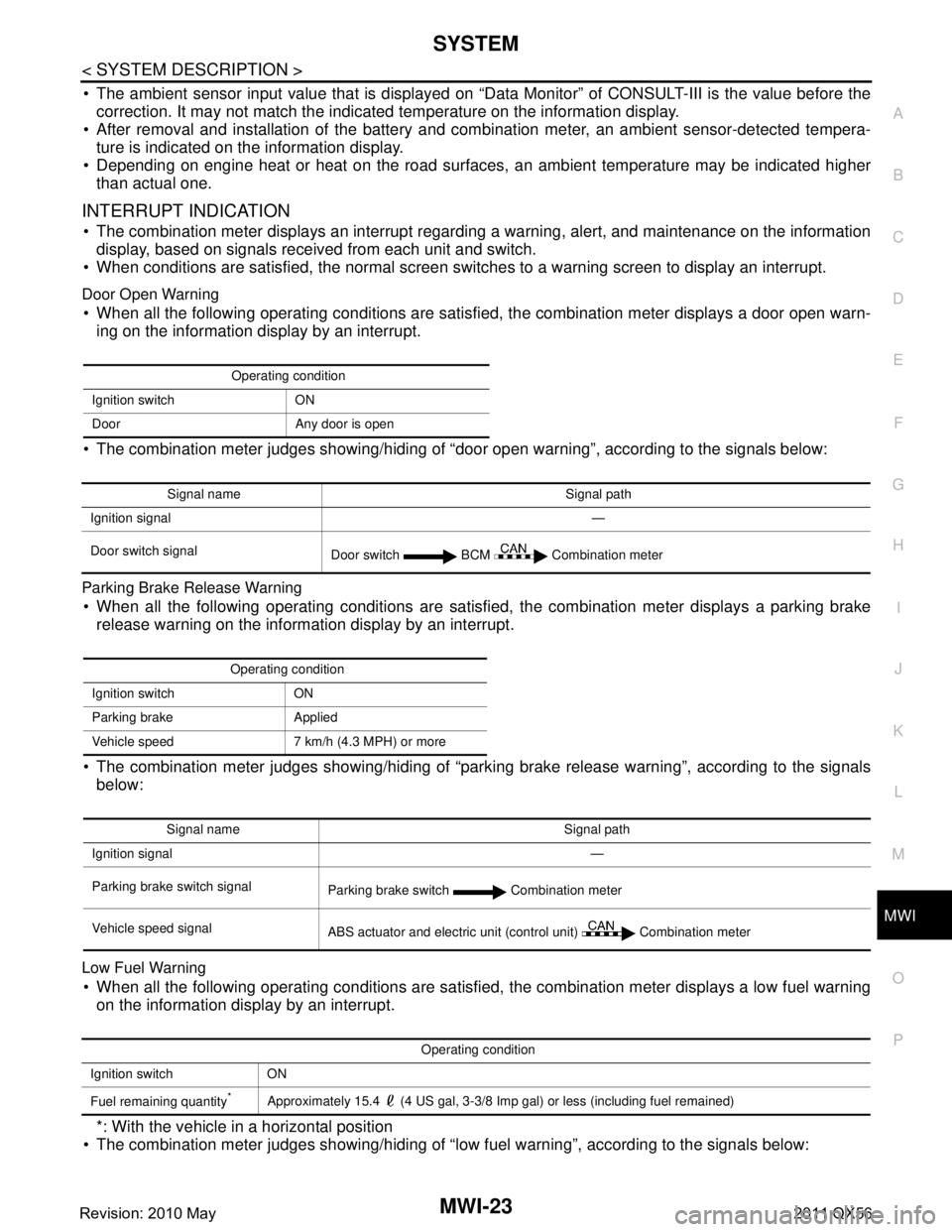
The ambient sensor input value that is displayed on “Data Monitor” of CONSULT-III is the value before the
correction. It may not match the indica ted temperature on the information display.
After removal and installation of the battery and comb ination meter, an ambient sensor-detected tempera-
ture is indicated on the information display.
Depending on engine heat or heat on the road surfaces, an ambient temperature may be indicated higher
than actual one.
INTERRUPT INDICATION
The combination meter displays an interrupt regarding a warning, alert, and maintenance on the information
display, based on signals received from each unit and switch.
When conditions are satisfied, the normal screen swit ches to a warning screen to display an interrupt.
Door Open Warning
When all the following operating conditions are satisfied, the combination meter displays a door open warn-
ing on the information display by an interrupt.
The combination meter judges showing/hiding of “door open warning”, according to the signals below:
Parking Brake Release Warning
When all the following operating conditions are satisfi ed, the combination meter displays a parking brake
release warning on the information display by an interrupt.
The combination meter judges showing/hiding of “parki ng brake release warning”, according to the signals
below:
Low Fuel Warning
When all the following operating conditions are satisfied, the combination meter displays a low fuel warning on the information display by an interrupt.
*: With the vehicle in a horizontal position
The combination meter judges showing/hiding of “low fuel warning”, according to the signals below:
Operating condition
Ignition switch ON
Door Any door is open
Signal name Signal path
Ignition signal —
Door switch signal Door switch BCM Combination meter
Operating condition
Ignition switch ON
Parking brake Applied
Vehicle speed 7 km/h (4.3 MPH) or more
Signal name Signal path
Ignition signal —
Parking brake switch signal Parking brake switch Combination meter
Vehicle speed signal ABS actuator and electric unit (control unit) Combination meter
Operating condition
Ignition switch ON
Fuel remaining quantity
*Approximately 15.4 (4 US gal, 3-3/8 Imp gal) or less (including fuel remained)
Revision: 2010 May2011 QX56
Page 3768 of 5598

MWI
SYSTEMMWI-25
< SYSTEM DESCRIPTION >
C
DE
F
G H
I
J
K L
M B A
O P
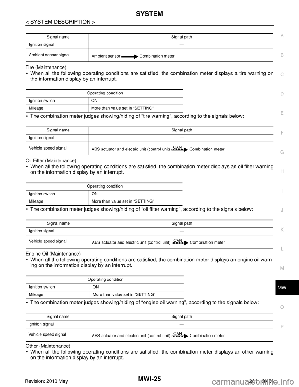
Tire (Maintenance) When all the following operating conditions are satisfied, the combination meter displays a tire warning on
the information display by an interrupt.
The combination meter judges showing/hiding of “tire warning”, according to the signals below:
Oil Filter (Maintenance)
When all the following operating conditions are satisfied, the combination meter displays an oil filter warning on the information display by an interrupt.
The combination meter judges showing/hiding of “oil filter warning”, according to the signals below:
Engine Oil (Maintenance)
When all the following operating conditions are satisfied, the combination meter displays an engine oil warn-
ing on the information display by an interrupt.
The combination meter judges showing/hiding of “engine oil warning”, according to the signals below:
Other (Maintenance)
When all the following operating conditions are satisfied, the combination meter displays an other warning on the information display by an interrupt.
Signal name Signal path
Ignition signal —
Ambient sensor signal Ambient sensor Combination meter
Operating condition
Ignition switch ON
Mileage More than value set in “SETTING”
Signal name Signal path
Ignition signal —
Vehicle speed signal ABS actuator and electric unit (control unit) Combination meter
Operating condition
Ignition switch ON
Mileage More than value set in “SETTING”
Signal name Signal path
Ignition signal —
Vehicle speed signal ABS actuator and electric unit (control unit) Combination meter
Operating condition
Ignition switch ON
Mileage More than value set in “SETTING”
Signal name Signal path
Ignition signal —
Vehicle speed signal ABS actuator and electric unit (control unit) Combination meter
Revision: 2010 May2011 QX56
Page 3769 of 5598

MWI-26
< SYSTEM DESCRIPTION >
SYSTEM
The combination meter judges showing/hiding of “other warning”, according to the signals below:
Meter Illumination Level Indication
When receiving the following signals, the combination meter causes an interrupt on the information display to
indicate an illumination level.
WARNING CHECK INDICATION
The combination meter can cause an interrupt on the information display to indicate a warning, based onsignals received from each unit and switch.
The indicated warning can be checked with “WARNING” during the satisfaction of an interrupt indication
condition for each warning.
SETTING
Warning indication timing and time can be set.
Alert
Setting values for travel time, and low ambient te mperature can be adjusted to meet the user's needs.
Maintenance
Setting values for engine oil, oil filter, tire, and other maintenance items can be adjusted to meet the user's
needs.
Options
Setting values for unit and effect items can be adjusted to meet the user's needs.
Operating condition
Ignition switch ON
Mileage More than value set in “SETTING”
Signal name Signal path
Ignition signal —
Vehicle speed signal ABS actuator and electric unit (control unit) Combination meter
Signal name Signal path
Ignition signal —
Illumination control switch signal (+) Trip reset and illumination control switch Combination meter
Illumination control switch signal ( −)
Setting item Setting range Setting unit
Alert Timer No setting, 0.5 h - 6 h 0.5 h
ICY ON/OFF —
Setting item Setting range
Maintenance Tire
No setting, 500 km - 30,000 km
(No setting, 250 mile - 18,500 mile)
Filter No setting, 500 km - 30,000 km
(No setting, 250 mile - 18,500 mile)
Oil No setting, 500 km - 30,000 km
(No setting, 250 mile - 18,500 mile)
Other No setting, 500 km - 30,000 km
(No setting, 250 mile - 18,500 mile)
Revision: 2010 May2011 QX56
Page 3832 of 5598

PB-1
BRAKES
C
DE
G H
I
J
K L
M
SECTION PB
A
B
PB
N
O P
CONTENTS
PARKING BRAKE SYSTEM
PREPARATION ............. ...............................2
PREPARATION .............................................. .....2
Commercial Service Tools .................................. ......2
PERIODIC MAINTENANCE ..........................3
PARKING BRAKE SYSTEM .......................... .....3
Inspection and Adjustment .................................. ......3
PARKING BRAKE SHOE ...................................4
Adjustment .......................................................... ......4
REMOVAL AND INSTALLATION ................5
PARKING BRAKE CONTROL ....................... .....5
Exploded View .................................................... ......5
Removal and Installation ..................................... .....5
Adjustment ................................................................6
PARKING BRAKE SHOE ..................................7
Exploded View ..........................................................7
Removal and Installation ..........................................7
Inspection and Adjustment .......................................8
SERVICE DATA AND SPECIFICATIONS
(SDS) ............... .............................................
10
SERVICE DATA AND SPECIFICATIONS
(SDS) .................................................................
10
Parking Drum Brake ............................................ ....10
Parking Brake Control .............................................10
Revision: 2010 May2011 QX56
Page 3834 of 5598

PARKING BRAKE SYSTEMPB-3
< PERIODIC MAINTENANCE >
C
DE
G H
I
J
K L
M A
B
PB
N
O P
PERIODIC MAINTENANCE
PARKING BRAKE SYSTEM
Inspection and AdjustmentINFOID:0000000006222510
INSPECTION
1. Operate the parking brake pedal with a force of 196 N ( 20 kg, 44 lb). Check that the pedal stroke is within
the specified number of notches. (Check it by listening to clicks of ratchet.)
2. When brake warning lamp turns ON, check that the pedal stroke is within the specified number of
notches. (Check it by listening to clicks of ratchet.)
Inspect Components
Check the following items and replace if necessary.
• Check each component for installation condition such as looseness.
Check the parking brake pedal assembly for bend, damage and cracks.
Check the cables and equalizer for wear, damage and cracks.
Check the parking brake switch. Refer to BRC-118, "
Component Inspection".
ADJUSTMENT
1. Remove the rear tires with power tool.
2. Fix the disc rotor using wheel nuts (2 points at least).
3. Release the parking brake pedal by turning the adjusting nut and loosening the cable.
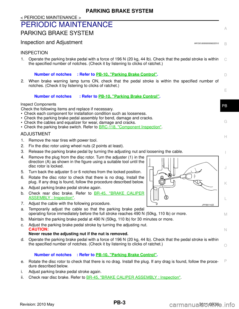
4. Remove the plug from the disc rotor. Turn the adjuster (1) in the
direction (A) as shown in the figure using a suitable tool until the
disc rotor is locked.
5. Turn back the adjuster 5 or 6 notches from the locked position.
6. Rotate the disc rotor to check that there is no drag. Install the plug. If any drag is found, follow the procedure described below.
a. Adjust parking brake pedal stroke again.
b. Check rear disc brake. Refer to BR-45, "
BRAKE CALIPER
ASSEMBLY : Inspection".
7. Adjust the cable with the following procedure.
a. Temporarily adjust the cable so that the parking brake pedal operating force immediately before the full stroke reaches 490 N (50kg, 110 lb) or more.
b. Maintain the parking brake pedal at 490 N (50kg, 110 lb) for 30 minutes or more.
c. Adjust the parking brake pedal st roke by turning the adjusting nut.
CAUTION:
Never reuse the adjusting nu t if the nut is removed.
d. Operate the parking brake pedal with a force of 196 N ( 20 kg, 44 lb). Check that the pedal stroke is within
the specified number of notches. (Check it by listening to clicks of ratchet.)
e. Rotate the disc rotor to check that there is no drag. Install the plug. If any drag is found, follow the proce-
dure described below.
i. Adjust parking brake pedal stroke again.
ii. Check rear disc brake. Refer to BR-45, "
BRAKE CALIPER ASSEMBLY : Inspection".
Number of notches : Refer to
PB-10, "
Parking Brake Control".
Number of notches : Refer to PB-10, "
Parking Brake Control".
Number of notches : Refer to PB-10, "
Parking Brake Control".
JPFIB0114ZZ
Revision: 2010 May2011 QX56
Page 3835 of 5598

PB-4
< PERIODIC MAINTENANCE >
PARKING BRAKE SHOE
PARKING BRAKE SHOE
AdjustmentINFOID:0000000006222511
1. Adjust parking brake pedal stroke. Refer to PB-3, "Inspection and Adjustment".
2. Perform parking brake break-in (drag on) operati on by driving vehicle under the following conditions:
Drive forward
Vehicle speed: Approx. 83 km/h (51. 6 MPH) set (constant and forward)
Parking brake pedal operating force: 255 N ( 26.0 kg, 57.3 lb) (9 notches) set contact
Time: Approx. 33 sec.
CAUTION:
• To prevent lining from getting t oo hot, allow a cool off period of approx. 5 minutes after every
break-in operation.
Never perform excessive break-in operations, b ecause doing so may cause uneven or early wear
of the lining.
3. After the break-in procedure, check park ing brake pedal stroke of parking brake.
CAUTION:
If it is out of the specification, adjust again. Refer to Refer to PB-3, "
Inspection and Adjustment".
Revision: 2010 May2011 QX56
Page 3844 of 5598
![INFINITI QX56 2011 Factory Service Manual
PCS
PRECAUTIONSPCS-3
< PRECAUTION > [IPDM E/R]
C
D
E
F
G H
I
J
K L
B A
O P
N
PRECAUTION
PRECAUTIONS
Precaution for Supplemental
Restraint System (SRS) "AIR BAG" and "SEAT BELT
PRE-TENSIONER"
INFOID INFINITI QX56 2011 Factory Service Manual
PCS
PRECAUTIONSPCS-3
< PRECAUTION > [IPDM E/R]
C
D
E
F
G H
I
J
K L
B A
O P
N
PRECAUTION
PRECAUTIONS
Precaution for Supplemental
Restraint System (SRS) "AIR BAG" and "SEAT BELT
PRE-TENSIONER"
INFOID](/manual-img/42/57033/w960_57033-3843.png)
PCS
PRECAUTIONSPCS-3
< PRECAUTION > [IPDM E/R]
C
D
E
F
G H
I
J
K L
B A
O P
N
PRECAUTION
PRECAUTIONS
Precaution for Supplemental
Restraint System (SRS) "AIR BAG" and "SEAT BELT
PRE-TENSIONER"
INFOID:0000000006220159
The Supplemental Restraint System such as “A IR BAG” and “SEAT BELT PRE-TENSIONER”, used along
with a front seat belt, helps to reduce the risk or severi ty of injury to the driver and front passenger for certain
types of collision. This system includes seat belt switch inputs and dual stage front air bag modules. The SRS
system uses the seat belt switches to determine the front air bag deployment, and may only deploy one front
air bag, depending on the severity of a collision and whether the front occupants are belted or unbelted.
Information necessary to service the system safely is included in the “SRS AIR BAG” and “SEAT BELT” of this
Service Manual.
WARNING:
• To avoid rendering the SRS inoper ative, which could increase the risk of personal injury or death in
the event of a collision that would result in air ba g inflation, all maintenance must be performed by
an authorized NISSAN/INFINITI dealer.
Improper maintenance, including in correct removal and installation of the SRS, can lead to personal
injury caused by unintentional act ivation of the system. For removal of Spiral Cable and Air Bag
Module, see the “SRS AIR BAG”.
Do not use electrical test equipm ent on any circuit related to the SRS unless instructed to in this
Service Manual. SRS wiring harnesses can be identi fied by yellow and/or orange harnesses or har-
ness connectors.
PRECAUTIONS WHEN USING POWER TOOLS (AIR OR ELECTRIC) AND HAMMERS
WARNING:
When working near the Air Bag Diagnosis Sensor Unit or other Air Bag System sensors with the
ignition ON or engine running, DO NOT use air or electric power tools or strike near the sensor(s)
with a hammer. Heavy vibration could activate the sensor(s) and deploy the air bag(s), possibly
causing serious injury.
When using air or electric power tools or hammers , always switch the ignition OFF, disconnect the
battery, and wait at least 3 minutes before performing any service.
Revision: 2010 May2011 QX56