2011 INFINITI QX56 maintenance
[x] Cancel search: maintenancePage 2930 of 5598
FL-1
ENGINE
C
DE
F
G H
I
J
K L
M
SECTION FL
A
FL
N
O P
CONTENTS
FUEL SYSTEM
PRECAUTION ................ ...............................2
PRECAUTIONS .............................................. .....2
General Precautions ........................................... ......2
PREPARATION ............................................3
PREPARATION .............................................. .....3
Special Service Tool ........................................... ......3
Commercial Service Tools ........................................3
PERIODIC MAINTENANCE ..........................4
FUEL SYSTEM ............................................... .....4
Inspection ............................................................ ......4
Quick Connector .......................................................4
REMOVAL AND INSTALLATION ................5
FUEL LEVEL SENSOR UNIT, FUEL FILTER
AND FUEL PUMP ASSEMBLY ..................... .....
5
Exploded View .................................................... ......5
Removal and Installation ..................................... .....5
Inspection .................................................................7
FUEL TANK ..................................... ..................8
Exploded View ..................................................... .....8
Removal and Installation ..........................................8
Inspection .................................................................9
EVAP CANISTER ..............................................10
Exploded View .........................................................10
Hydraulic Layout ......................................................10
Removal and Installation .........................................12
Disassembly and Assembly .....................................12
Inspection ................................................................12
SERVICE DATA AND SPECIFICATIONS
(SDS) ............... .............................................
13
SERVICE DATA AND SPECIFICATIONS
(SDS) .................................................................
13
Fuel Tank ............................................................. ....13
Revision: 2010 May2011 QX56
Page 2933 of 5598
FL-4
< PERIODIC MAINTENANCE >
FUEL SYSTEM
PERIODIC MAINTENANCE
FUEL SYSTEM
InspectionINFOID:0000000006289682
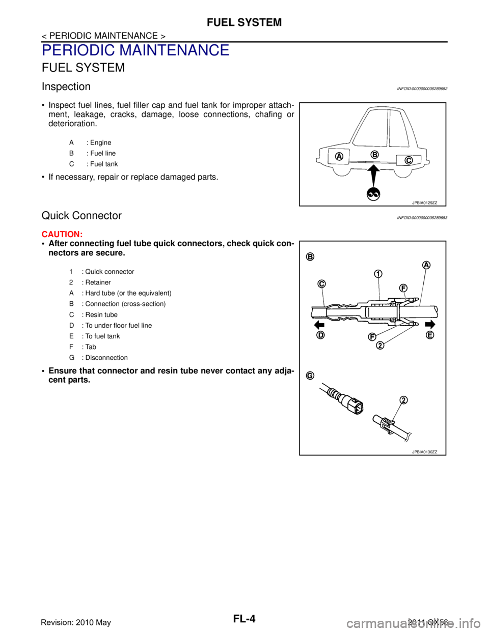
• Inspect fuel lines, fuel filler cap and fuel tank for improper attach-ment, leakage, cracks, damage, loose connections, chafing or
deterioration.
If necessary, repair or replace damaged parts.
Quick ConnectorINFOID:0000000006289683
CAUTION:
After connecting fuel tube quick connectors, check quick con-
nectors are secure.
Ensure that connector and resi n tube never contact any adja-
cent parts.
A : Engine
B : Fuel line
C: Fuel tank
JPBIA0129ZZ
1 : Quick connector
2: Retainer
A : Hard tube (or the equivalent)
B : Connection (cross-section)
C : Resin tube
D : To under floor fuel line
E : To fuel tank
F: Tab
G : Disconnection
JPBIA0130ZZ
Revision: 2010 May2011 QX56
Page 2943 of 5598
FSU-1
SUSPENSION
C
DF
G H
I
J
K L
M
SECTION FSU
A
B
FSU
N
O PCONTENTS
FRONT SUSPENSION
PRECAUTION ................ ...............................2
PRECAUTIONS .............................................. .....2
Precaution for Supplemental Restraint System
(SRS) "AIR BAG" and "SEAT BELT PRE-TEN-
SIONER" ............................................................. ......
2
Precaution Necessary for Steering Wheel Rota-
tion after Battery Disconnect .....................................
2
Precaution for Procedure without Cowl Top Cover ......3
Precautions for Suspension ......................................3
PREPARATION ............................................4
PREPARATION .............................................. .....4
Special Service Tools .......................................... ......4
Commercial Service Tools ........................................4
SYMPTOM DIAGNOSIS ...............................5
NOISE, VIBRATION AND HARSHNESS
(NVH) TROUBLESHOOTING ........................ .....
5
NVH Troubleshooting Chart ................................ ......5
PERIODIC MAINTENANCE ..........................6
FRONT SUSPENSION ASSEMBLY .............. .....6
Inspection ............................................................ ......6
WHEEL ALIGNMENT ..........................................7
Inspection ............................................................ ......7
Adjustment ................................................................7
REMOVAL AND INSTALLATION ................9
FRONT COIL SPRING AND SHOCK AB-
SORBER ............................................................
9
Exploded View ..................................................... .....9
Removal and Installation .........................................10
Disassembly and Assembly .....................................11
Inspection and Adjustment ......................................12
Disposal ...................................................................13
LOWER LINK ....................................................14
Exploded View .........................................................14
Removal and Installation .........................................14
Inspection ................................................................15
UPPER LINK ......................... ............................17
Exploded View ..................................................... ....17
Removal and Installation .........................................17
Inspection ................................................................18
FRONT STABILIZER ........................................20
Exploded View .........................................................20
Removal and Installation .........................................20
Inspection ................................................................20
SERVICE DATA AND SPECIFICATIONS
(SDS) ............... .............................................
21
SERVICE DATA AND SPECIFICATIONS
(SDS) .................................................................
21
Wheel Alignment ................................................. ....21
Ball Joint ..................................................................21
Wheel Height ...........................................................21
Revision: 2010 May2011 QX56
Page 2944 of 5598

FSU-2
< PRECAUTION >
PRECAUTIONS
PRECAUTION
PRECAUTIONS
Precaution for Supplemental Restraint System (SRS) "AIR BAG" and "SEAT BELT
PRE-TENSIONER"
INFOID:0000000006271944
The Supplemental Restraint System such as “A IR BAG” and “SEAT BELT PRE-TENSIONER”, used along
with a front seat belt, helps to reduce the risk or severi ty of injury to the driver and front passenger for certain
types of collision. This system includes seat belt switch inputs and dual stage front air bag modules. The SRS
system uses the seat belt switches to determine the front air bag deployment, and may only deploy one front
air bag, depending on the severity of a collision and w hether the front occupants are belted or unbelted.
Information necessary to service the system safely is included in the “SRS AIR BAG” and “SEAT BELT” of this
Service Manual.
WARNING:
• To avoid rendering the SRS inopera tive, which could increase the risk of personal injury or death in
the event of a collision that would result in air bag inflation, all maintenance must be performed by
an authorized NISS AN/INFINITI dealer.
Improper maintenance, including in correct removal and installation of the SRS, can lead to personal
injury caused by unintent ional activation of the system. For re moval of Spiral Cable and Air Bag
Module, see the “SRS AIR BAG”.
Do not use electrical test equipmen t on any circuit related to the SRS unless instructed to in this
Service Manual. SRS wiring harnesses can be identi fied by yellow and/or orange harnesses or har-
ness connectors.
PRECAUTIONS WHEN USING POWER TOOLS (AIR OR ELECTRIC) AND HAMMERS
WARNING:
When working near the Air Bag Diagnosis Sensor Unit or other Air Bag System sensors with the ignition ON or engine running, DO NOT use air or electric power tools or strike near the sensor(s)
with a hammer. Heavy vibration could activate the sensor(s) and deploy the air bag(s), possibly
causing serious injury.
When using air or electric power tools or hammers , always switch the ignition OFF, disconnect the
battery, and wait at least 3 minu tes before performing any service.
Precaution Necessary for Steering W heel Rotation after Battery Disconnect
INFOID:0000000006271945
NOTE:
Before removing and installing any control units, first tu rn the push-button ignition switch to the LOCK posi-
tion, then disconnect bot h battery cables.
After finishing work, confirm that all control unit connectors are connected properly, then re-connect both
battery cables.
Always use CONSULT-III to perform self-diagnosis as a part of each function inspection after finishing work.
If a DTC is detected, perform trouble diagnos is according to self-diagnosis results.
For vehicle with steering lock unit, if the battery is disconnected or discharged, the steering wheel will lock and
cannot be turned.
If turning the steering wheel is required with the bat tery disconnected or discharged, follow the operation pro-
cedure below before starting the repair operation.
OPERATION PROCEDURE
1. Connect both battery cables. NOTE:
Supply power using jumper cables if battery is discharged.
2. Turn the push-button ignition switch to ACC position. (At this time, the steering lock will be released.)
3. Disconnect both battery cables. The steering lock wi ll remain released with both battery cables discon-
nected and the steering wheel can be turned.
4. Perform the necessary repair operation.
Revision: 2010 May2011 QX56
Page 2948 of 5598
FSU-6
< PERIODIC MAINTENANCE >
FRONT SUSPENSION ASSEMBLY
PERIODIC MAINTENANCE
FRONT SUSPENSION ASSEMBLY
InspectionINFOID:0000000006225639
MOUNTING INSPECTION
Check the mounting conditions (looseness, backlash) of each component and component conditions (wear,
damage) are normal.
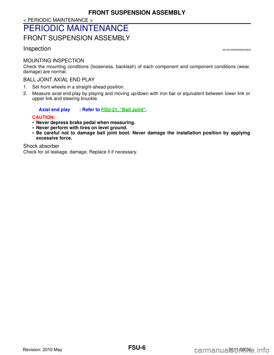
BALL JOINT AXIAL END PLAY
1. Set front wheels in a straight-ahead position.
2. Measure axial end play by playing and moving up/dow n with iron bar or equivalent between lower link or
upper link and steering knuckle.
CAUTION:
Never depress brake pedal when measuring.
Never perform with tires on level ground.
Be careful not to damage ball joint boot. Never damage the installation position by applying
excessive force.
Shock absorber
Check for oil leakage, damage. Replace it if necessary. Axial end play : Refer to
FSU-21, "
Ball Joint".
Revision: 2010 May2011 QX56
Page 2949 of 5598
WHEEL ALIGNMENTFSU-7
< PERIODIC MAINTENANCE >
C
DF
G H
I
J
K L
M A
B
FSU
N
O P
WHEEL ALIGNMENT
InspectionINFOID:0000000006225640
DESCRIPTION
Measure wheel alignment under unladen conditions.
NOTE:
“Unladen conditions” means that fuel, engine coolant, and lubricant are full. Spare tire, jack, hand tools and
mats are in designated positions.
PRELIMINARY CHECK
Check the following:
Tires for improper air pressure and wear
Road wheels for runout: Refer to WT-64, "
Inspection".
Wheel bearing axial end play: Refer to FA X - 7 , "
Inspection" (2WD), FAX-16, "Inspection" (4WD).
Lower link and upper link ball joint axial end play: Refer to FSU-15, "
Inspection" and FSU-18, "Inspection".
Shock absorber operation.
Each mounting part of axle and suspension for looseness and deformation
Lower link for cracks, deformation and other damage
Vehicle height (posture)
GENERAL INFORMATION AND RECOMMENDATIONS
A four-wheel thrust alignment should be performed.
- This type of alignment is recomm ended for any NISSAN/INFINITI vehicle.
- The four-wheel “thrust” process helps ensure that t he vehicle is properly aligned and the steering wheel is
centered.
- The alignment rack itself should be capable of accepting any NISSAN/INFINITI vehicle.
- The rack should be checked to ensure that it is level.
Make sure the machine is properly calibrated.
- Your alignment equipment should be regularly ca librated in order to give correct information.
- Check with the manufacturer of your specific equi pment for their recommended Service/Calibration Sched-
ule.
ALIGNMENT PROCESS
IMPORTANT:
Use only the alignment specificati ons listed in this Service Manual.
When displaying the alignment settings, many alignment machines use “indicators”: (Green/red, plus or
minus, Go/No Go). Never use these indicators.
- The alignment specifications programmed into your machine that operate these indicators may not be cor-
rect.
- This may result in an ERROR.
Some newer alignment machines are equipped with an optional “Rolling Compensation” method to “com-
pensate” the sensors (alignment targets or head units). Never use this “Rolling Compensation” method.
- Use the “Jacking Compensation Method”. After installi ng the alignment targets or head units, raise the vehi-
cle and rotate the wheels 1/2 turn both ways.
- See Instructions in the alignment machine you're using for more information on this.
AdjustmentINFOID:0000000006225641
CAMBER, CASTER
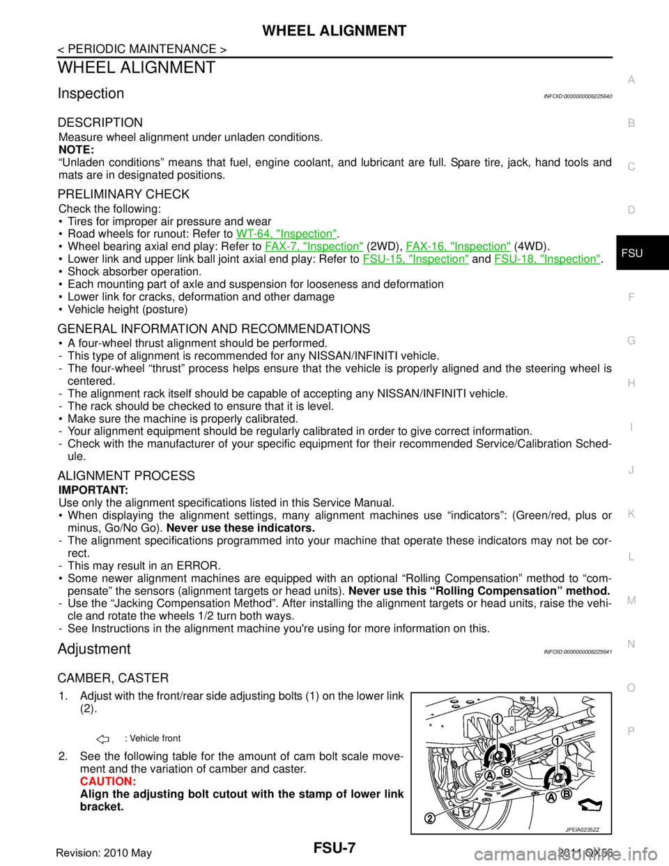
1. Adjust with the front/rear side adjusting bolts (1) on the lower link
(2).
2. See the following table for the amount of cam bolt scale move- ment and the variation of camber and caster.
CAUTION:
Align the adjusting bolt cutout with the stamp of lower link
bracket.
: Vehicle front
JPEIA0235ZZ
Revision: 2010 May2011 QX56
Page 2950 of 5598
FSU-8
< PERIODIC MAINTENANCE >
WHEEL ALIGNMENT
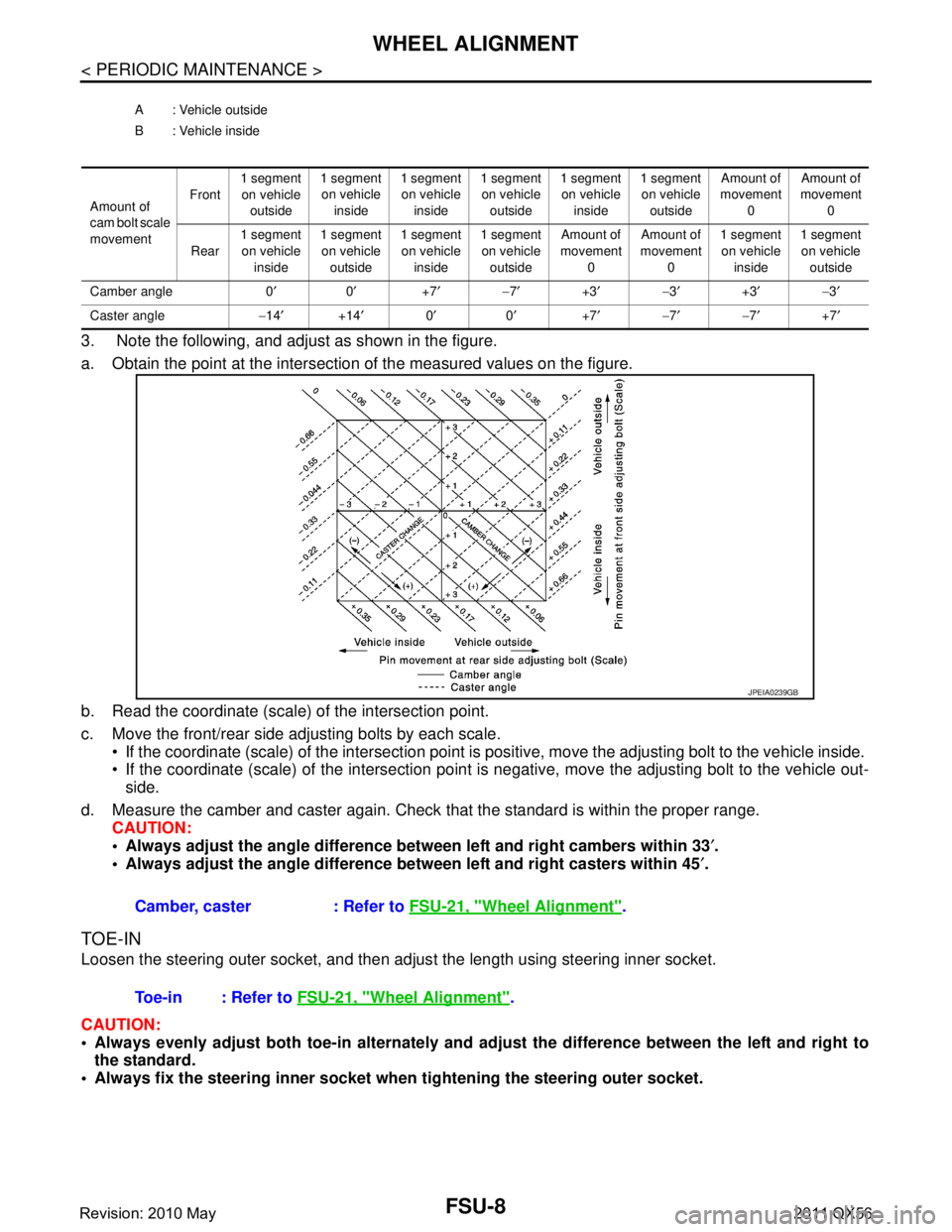
3. Note the following, and adjust as shown in the figure.
a. Obtain the point at the intersection of the measured values on the figure.
b. Read the coordinate (scale) of the intersection point.
c. Move the front/rear side adjusting bolts by each scale. If the coordinate (scale) of the intersection point is positive, move the adjusting bolt to the vehicle inside.
If the coordinate (scale) of the intersection point is negative, move the adjusting bolt to the vehicle out-
side.
d. Measure the camber and caster again. Check that the standard is within the proper range.
CAUTION:
Always adjust the angle difference betw een left and right cambers within 33′.
Always adjust the angle difference be tween left and right casters within 45′.
TOE-IN
Loosen the steering outer socket, and then adjus t the length using steering inner socket.
CAUTION:
Always evenly adjust both toe-in alternately and adjust the difference between the left and right to
the standard.
Always fix the steering inner socket when tightening the steering outer socket.
A : Vehicle outside
B : Vehicle inside
Amount of
cam bolt scale
movement Front
1 segment
on vehicle outside 1 segment
on vehicle inside 1 segment
on vehicle inside 1 segment
on vehicle outside 1 segment
on vehicle inside 1 segment
on vehicle outside Amount of
movement 0 Amount of
movement 0
Rear 1 segment
on vehicle inside 1 segment
on vehicle outside 1 segment
on vehicle inside 1 segment
on vehicle outside Amount of
movement 0 Amount of
movement 0 1 segment
on vehicle inside 1 segment
on vehicle outside
Camber angle 0 ′0′ +7′− 7′ +3′− 3′ +3′− 3′
Caster angle −14 ′ +14′ 0′ 0′ +7′− 7′− 7′ +7′
Camber, caster : Refer to FSU-21, "Wheel Alignment".
JPEIA0239GB
Toe-in : Refer to FSU-21, "Wheel Alignment".
Revision: 2010 May2011 QX56
Page 2980 of 5598

GI-16
< HOW TO USE THIS MANUAL >
ABBREVIATIONS
I
K
L
M
N
O
ABBREVIATION DESCRIPTIONI/M Inspection and maintenanceIA Intake air
IAC Idle air control IAT Intake air temperature
IBA Intelligent brake assist IC Ignition control
ICC Intelligent cruise control
ICM Ignition control module
IPDM E/R Intelligent power distribution module engine room ISC Idle speed controlISS Input shaft speed
ABBREVIATION DESCRIPTION KS Knock sensor
ABBREVIATION DESCRIPTION LCD Liquid crystal display
LCU Local control unitLDP Lane departure prevention
LDW Lane departure warning LED Light emitting diode LH Left-hand
LIN Local interconnect network
ABBREVIATION DESCRIPTION M/T Manual transaxle/transmission
MAF Mass airflow
MAP Manifold absolute pressure MI Malfunction indicator
MIL Malfunction indicator lamp
ABBREVIATION DESCRIPTION NOX Nitrogen oxides
ABBREVIATION DESCRIPTION O2 Oxygen
O2S Oxygen sensor
OBD On board diagnostic OC Oxidation catalytic converter
OD OverdriveOL Open loop
OSS Output shaft speed
Revision: 2010 May2011 QX56