2011 INFINITI QX56 check engine
[x] Cancel search: check enginePage 3075 of 5598
REFRIGERANTHA-19
< BASIC INSPECTION >
C
DE
F
G H
J
K L
M A
B
HA
N
O P
Never look directly into UV lamp light source.
NOTE:
For continuous operating time of UV lamp, fo llow the manufacturer operating instructions.
Illuminate piping joints from different angles us ing UV lamp and check that there is no leakage.
Use a mirror in area that is difficult to see to check refrigerant leakage.
Refrigerant leakage from evaporator can be detected by soaking cotton swab or a similar material with
drain hose water and illuminating it using UV lamp.
Dust, dirt, and packing materials adhesive used for condenser, evaporator, and other locations may flu- oresce. Be careful not to misidentify leakage.
5. Repair or replace parts where refrigerant leak age occurs and wipe off fluorescent leak detection dye.
NOTE:
Completely wipe off fluorescent leak detection dy e from gaps between parts, screw threads, and others
using a cotton swab or similar materials.
6. Use a UV lamp to check that no fluorescent leak detection dye remains after finishing work. WARNING:
Never look directly into UV lamp light source.
NOTE:
For continuous operating time of UV lamp, fo llow the manufacturer operating instructions.
Dust, dirt, and packing materials adhesive used for condenser, evaporator, and other locations may flu-
oresce. Be careful not to misidentify leakage.
CHECK REFRIGERANT LEAKAGE USIN G ELECTRICAL LEAK DETECTOR
WARNING:
Never check refrigerant leakage while the engine is running.
CAUTION:
Be careful of the following items so that in accurate checks or misidentifications are avoided.
Never allow refrigerant vapor, shop chemical vapors, cigarette smoke, or others around the vehicle.
Always check refrigerant leakage in a low air flow environment so that refrigerant may not disperse
when leakage occurs.
1. Stop the engine.
2. Connect recovery/recycling/recharging equipment or manifold gauge set to A/C service valve.
3. Check that A/C refrigerant pressure is 345 kPa (3.52 kg/cm
2, 50 psi) or more when temperature is 16 °C
(61 °F) or more. When pressure is lower than the spec ified value, recycle refrigerant completely and fill
refrigerant to the specified level.
NOTE:
Leakages may not be detected if A/C refri gerant pressure is 345 kPa (3.52 kg/cm
2, 50 psi) or less when
temperature is less than 16 °C (61 °F).
4. Clean area where refrigerant leakage check is per formed, and check refrigerant leakage along all sur-
faces of pipe connections and A/C system com ponents using electrical leak detector probe.
CAUTION:
Continue checking when a leakage is found. Always continue and complete checking along all
pipe connections and A/C system co mponents for additional leakage.
When a leakage is detected, clean leakage area using compressed air and check again.
When checking leakage of cooling unit inside, al ways clean inside of drain hose so that the
probe surface may not be exposed to water or dirt.
NOTE:
Always check leakage starting from high-pressure side and continue to low-pressure side.
When checking leakage of cooling unit inside, operate blower fan motor for 15 minutes or more at the maximum fan speed while the engine is stopped, and then insert electrical leak detector probe into drain
hose and hold for 10 minutes or more.
When disconnecting shut-off valve that is connected to A/C service valve, always evacuate remaining
refrigerant so that misidentification can be avoided.
5. Repair or replace parts where refrigerant leak age is detected. (Leakage is detected but leakage area is
unknown. GO TO 6.)
6. Start the engine and set A/C control in the following conditions. A/C switch ON
Air flow: VENT (ventilation)
Intake door position: Recirculation
Revision: 2010 May2011 QX56
Page 3076 of 5598
HA-20
< BASIC INSPECTION >
REFRIGERANT
Temperature setting: Full cold
Fan speed: Maximum speed set
7. Run the engine at approximately 1,500 rpm for 2 minutes or more.
8. Stop the engine. Check again for refrigerant leakage. GO TO 4.
WARNING:
Be careful not to get burned when the engine is hot.
NOTE:
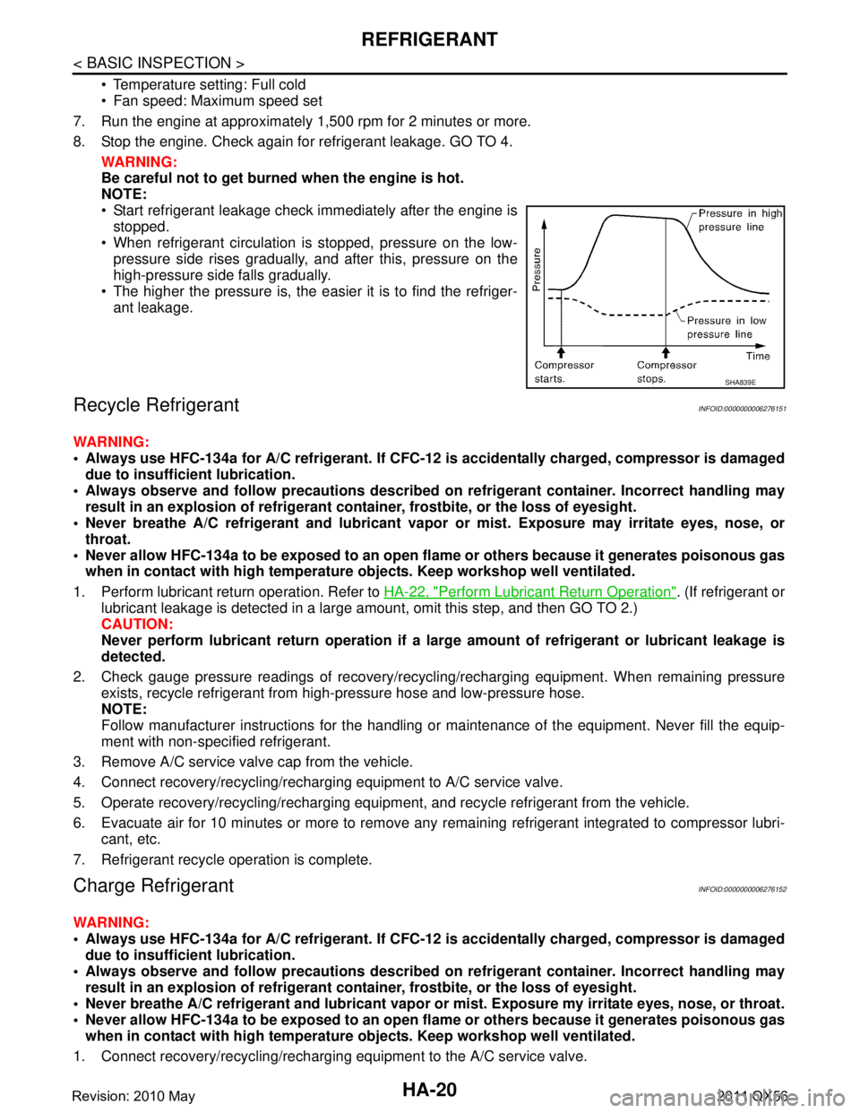
Start refrigerant leakage check immediately after the engine is stopped.
When refrigerant circulation is stopped, pressure on the low-
pressure side rises gradually, and after this, pressure on the
high-pressure side falls gradually.
The higher the pressure is, the easier it is to find the refriger-
ant leakage.
Recycle RefrigerantINFOID:0000000006276151
WARNING:
Always use HFC-134a for A/C refrigerant. If CFC-12 is accidentally charged, compressor is damaged
due to insufficient lubrication.
Always observe and follow precaution s described on refrigerant container. Incorrect handling may
result in an explosion of refrigerant co ntainer, frostbite, or the loss of eyesight.
Never breathe A/C refrigerant and lubricant vapor or mist. Exposure may irritate eyes, nose, or
throat.
Never allow HFC-134a to be exposed to an open flam e or others because it generates poisonous gas
when in contact with high temperature ob jects. Keep workshop well ventilated.
1. Perform lubricant return operation. Refer to HA-22, "
Perform Lubricant Return Operation". (If refrigerant or
lubricant leakage is detected in a large am ount, omit this step, and then GO TO 2.)
CAUTION:
Never perform lubricant return op eration if a large amount of refrigerant or lubricant leakage is
detected.
2. Check gauge pressure readings of recovery/recyc ling/recharging equipment. When remaining pressure
exists, recycle refrigerant from high-pressure hose and low-pressure hose.
NOTE:
Follow manufacturer instructions for the handling or maintenance of the equipment. Never fill the equip-
ment with non-specified refrigerant.
3. Remove A/C service valve cap from the vehicle.
4. Connect recovery/recycling/rechargi ng equipment to A/C service valve.
5. Operate recovery/recycling/recharging equipm ent, and recycle refrigerant from the vehicle.
6. Evacuate air for 10 minutes or more to remove any remaining refrigerant integrated to compressor lubri-
cant, etc.
7. Refrigerant recycle operation is complete.
Charge RefrigerantINFOID:0000000006276152
WARNING:
Always use HFC-134a for A/C refrigerant. If CFC-12 is accidentally charged, compressor is damaged
due to insufficient lubrication.
Always observe and follow precaution s described on refrigerant container. Incorrect handling may
result in an explosion of refrigerant co ntainer, frostbite, or the loss of eyesight.
Never breathe A/C refrigerant and lubricant vapor or mist. Exposure my irritate eyes, nose, or throat.
Never allow HFC-134a to be exposed to an open flam e or others because it generates poisonous gas
when in contact with high temperature ob jects. Keep workshop well ventilated.
1. Connect recovery/recycling/recharging equipment to the A/C service valve.
SHA839E
Revision: 2010 May2011 QX56
Page 3078 of 5598
HA-22
< BASIC INSPECTION >
LUBRICANT
LUBRICANT
DescriptionINFOID:0000000006276153
MAINTENANCE OF LUBRICANT LEVEL
The compressor lubricant is circulating in the system together with the refrigerant. It is necessary to fill com-
pressor with lubricant when replacing A/C system pa rts or when a large amount of refrigerant leakage is
detected. It is important to always maintain lubricant level within the specified level. Otherwise, the following
conditions may occur.
Insufficient lubricant amount: Stuck compressor
Excessive lubricant amount: Insufficient cooling (caused by insufficient heat exchange)
InspectionINFOID:0000000006276154
If a compressor is malfunctioning (internal noise, insufficient cooling), check the compressor oil.
1.COMPRESSOR OIL JUDGMENT
1. Remove the compressor. Refer to HA-30, "
Exploded View".
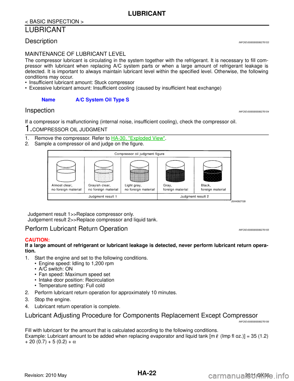
2. Sample a compressor oil and judge on the figure.
Judgement result 1>>Replace compressor only.
Judgement result 2>>Replace compressor and liquid tank.
Perform Lubricant Return OperationINFOID:0000000006276155
CAUTION:
If a large amount of refrigerant or lubricant leakag e is detected, never perform lubricant return opera-
tion.
1. Start the engine and set to the following conditions.
Engine speed: Idling to 1,200 rpm
A/C switch: ON
Fan speed: Maximum speed set
Intake door position: Recirculation
Temperature setting: Full cold
2. Perform lubricant return operation for approximately 10 minutes.
3. Stop the engine.
4. Lubricant return operation is complete.
Lubricant Adjusting Procedure for Comp onents Replacement Except Compressor
INFOID:0000000006276156
Fill with lubricant for the amount that is calculated according to the following conditions.
Example: Lubricant amount to be added when replacing evapor ator and liquid tank [m (Imp fl oz.)] = 35 (1.2)
+ 20 (0.7) + 5 (0.2) + α
Name A/C System Oil Type S
JSIIA0927GB
Revision: 2010 May2011 QX56
Page 3081 of 5598
PERFORMANCE TESTHA-25
< BASIC INSPECTION >
C
DE
F
G H
J
K L
M A
B
HA
N
O P
PERFORMANCE TEST
InspectionINFOID:0000000006276158
INSPECTION PROCEDURE
1. Connect recovery/recycling/recharging equipment (for HFC-134a) or manifold gauge.
2. Start the engine, and set to the following condition.
Test condition
3. Maintain test condition until A/C system becomes stable. (Approximately 10 minutes)
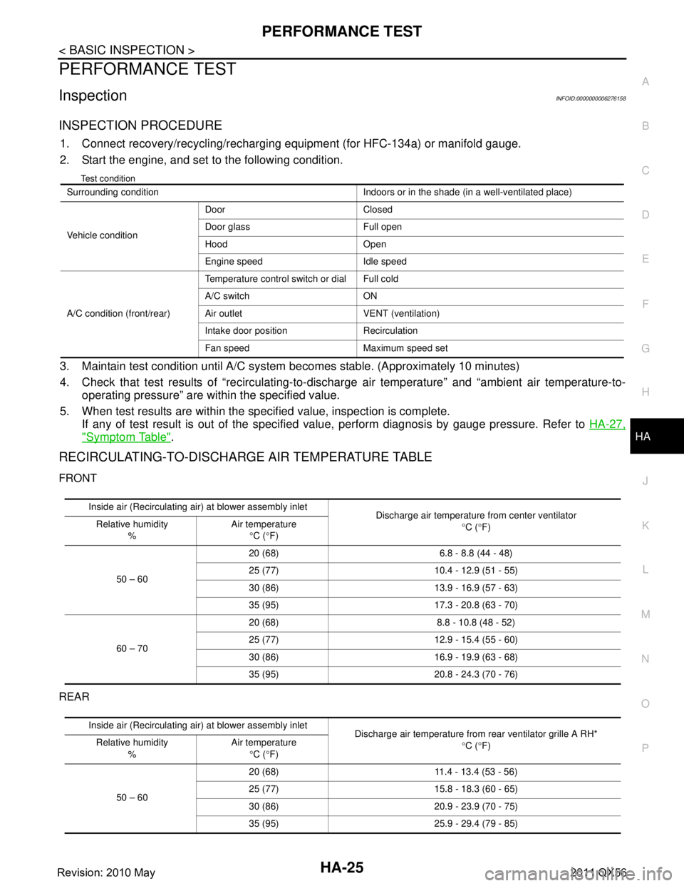
4. Check that test results of “recirculating-to-disc harge air temperature” and “ambient air temperature-to-
operating pressure” are within the specified value.
5. When test results are within the specified value, inspection is complete. If any of test result is out of the specified value, perform diagnosis by gauge pressure. Refer to HA-27,
"Symptom Table".
RECIRCULATING-TO-DISCHARGE AIR TEMPERATURE TABLE
FRONT
REAR
Surrounding condition Indoors or in the shade (in a well-ventilated place)
Vehicle conditionDoor Closed
Door glass Full open
Hood Open
Engine speed Idle speed
A/C condition (front/rear) Temperature control switch or dial Full cold
A/C switch ON
Air outlet VENT (ventilation)
Intake door position Recirculation
Fan speed Maximum speed set
Inside air (Recirculating air) at blower assembly inlet
Discharge air temperature from center ventilator
°C ( °F)
Relative humidity
% Air temperature
°C ( °F)
50 – 60 20 (68) 6.8 - 8.8 (44 - 48)
25 (77) 10.4 -
12.9 (51 - 55)
30 (86) 13.9 - 16.9 (57 - 63)
35 (95) 17.3 - 20.8 (63 - 70)
60 – 70 20 (68) 8.8 - 10.8 (48 - 52)
25 (77) 12.9 -
15.4 (55 - 60)
30 (86) 16.9 - 19.9 (63 - 68)
35 (95) 20.8 - 24.3 (70 - 76)
Inside air (Recirculating air) at blower assembly inlet
Discharge air temperature from rear ventilator grille A RH*
°C ( °F)
Relative humidity
% Air temperature
°C ( °F)
50 – 60 20 (68) 11.4 -
13.4 (53 - 56)
25 (77) 15.8 - 18.3 (60 - 65)
30 (86) 20.9 - 23.9 (70 - 75)
35 (95) 25.9 - 29.4 (79 - 85)
Revision: 2010 May2011 QX56
Page 3092 of 5598
HA-36
< REMOVAL AND INSTALLATION >
COOLER PIPE AND HOSE
9. Partly remove rear half of front fender protector RH. Refer to EXT-23, "FENDER PROTECTOR : Exploded
View".
10. Remove high-pressure pipe.
INSTALLATION
Note the following items, and install in the reverse order of removal.
CAUTION:
Replace O-rings with new ones. Then apply compressor oil to them when installing.
Check for leakages when recharging refrigerant. Refer to HA-18, "
Leak Test".
LOW-PRESSURE PIPE
LOW-PRESSURE PIPE : Removal and InstallationINFOID:0000000006276176
CAUTION:
Perform lubricant return operation before each re frigeration system disassembly. However, if a large
amount of refrigerant or lubrican t is detected, never perform lubricant return operation. Refer to HA-
22, "Perform Lubricant Return Operation".
REMOVAL
1. Use a refrigerant collecting equipment (for HF C-134a) to discharge the refrigerant. Refer to HA-22, "Per-
form Lubricant Return Operation".
2. Drain engine coolant from cooling system. Refer to CO-8, "
Draining".
3. Remove engine cover. Refer to EM-25, "
Removal and Installation".
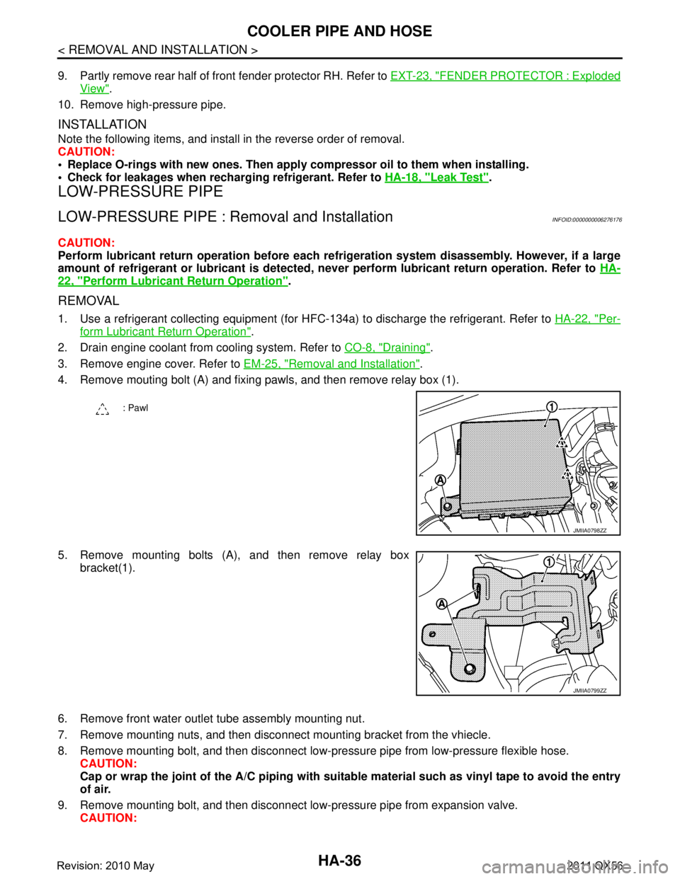
4. Remove mouting bolt (A) and fixing pawls, and then remove relay box (1).
5. Remove mounting bolts (A), and then remove relay box bracket(1).
6. Remove front water outlet tube assembly mounting nut.
7. Remove mounting nuts, and then disconnec t mounting bracket from the vhiecle.
8. Remove mounting bolt, and then disconnect low-pressure pipe from low-pressure flexible hose. CAUTION:
Cap or wrap the joint of the A/C piping with suitab le material such as vinyl tape to avoid the entry
of air.
9. Remove mounting bolt, and then disconnect low-pressure pipe from expansion valve. CAUTION:
: Pawl
JMIIA0798ZZ
JMIIA0799ZZ
Revision: 2010 May2011 QX56
Page 3099 of 5598
A/C UNIT ASSEMBLYHA-43
< REMOVAL AND INSTALLATION >
C
DE
F
G H
J
K L
M A
B
HA
N
O P
Perform lubricant return operati on before each refrigeration system disassembly. However, if a large
amount of refrigerant or lubricant is detected, n ever perform lubricant return operation. Refer to HA-
22, "Perform Lubricant Return Operation".
REMOVAL
1. Use a refrigerant collecting equipment (for HF C-134a) to discharge the refrigerant. Refer to HA-20, "Recy-
cle Refrigerant". (If equipped)
2. Drain engine coolant from cooling system. Refer to CO-8, "
Draining".
3. Remove clamps, and then disconnect front heater outlet hose from heater pipe.
CAUTION:
Some coolant may spill when heater hoses are disconnected.
Close off the coolant inlet and outlet on the heater core (2 locations) with shop cloths.
4. Remove mounting bolt, and then disconnect low-pressure pipe and high-pressure pipe from expansion valve.
CAUTION:
Cap or wrap the joint of the A/C piping and expan sion valve with suitable material such as vinyl
tape to avoid the entry of air.
5. Remove instrument panel assembly. Refer to IP-14, "
Removal and Installation".
6. Remove steering column mounting bolt and nuts. Refer to ST-34, "
Removal and Installation".
7. Move steering column assembly to a position where it does not inhibit work.
8. Disconnect harness clips, harness connectors, ground bol ts and blackets from steering member, and then
move the vehicle harness to the position without hindrance for work.
9. Remove mounting nuts, and then remove instrument stay (RH and LH).
10. Remove A/C unit assembly mounting bolts.
11. Remove mounting bolts, and then remove steering member from the vehicle.
12. Disconnect drain hose from A/C unit assembly, and then remove A/C unit assembly from the vehicle.
13. Remove mounting bolts, and then disconnect heater & cooling unit and blower unitassembly.
INSTALLATION
Note the following items, and install in the reverse order of removal.
CAUTION:
Replace O-rings with new ones. Then apply compressor oil to them when installing.
Check for leakages when recharging refrigerant. Refer to HA-18, "
Leak Test".
NOTE:
Refer to CO-9, "
Refilling" when filling radiator with engine coolant.
EVAPORATOR
EVAPORATOR : Removal and InstallationINFOID:0000000006276184
REMOVAL
1. Remove heater & cooling unit assembly. Refer to HA-41, "Exploded View".
2. Remove heater core. Refer to HA-44, "
HEATER CORE : Removal and Installation".
3. Remove mounting screws, and then remove evaporator pipe cover.
4. Remove air mix door motor (RH). Refer to HAC-153, "
AIR MIX DOOR MOTOR : Removal and Installa-
tion".
5. Remove mounting screws, and then remove A/C cover.
6. Remove foot duct LH. Refer to VTL-11, "
FLOOR DUCT 1 : Removal and Installation".
7. Remove mounting screws, and then remove A/C lower case.
8. Remove intake sensor. Refer to HAC-150, "
Removal and Installation".
9. Remove evaporator assembly from heater & cooling unit assembly.
10. Remove mounting bolts, and then remove evaporator from evaporator assembly.
CAUTION:
Cap or wrap the joint of the evaporator and evaporat or pipe assembly with suitable material such as
vinyl tape to avoid the entry of air.
Revision: 2010 May2011 QX56
Page 3105 of 5598
REAR A/C UNITHA-49
< REMOVAL AND INSTALLATION >
C
DE
F
G H
J
K L
M A
B
HA
N
O P
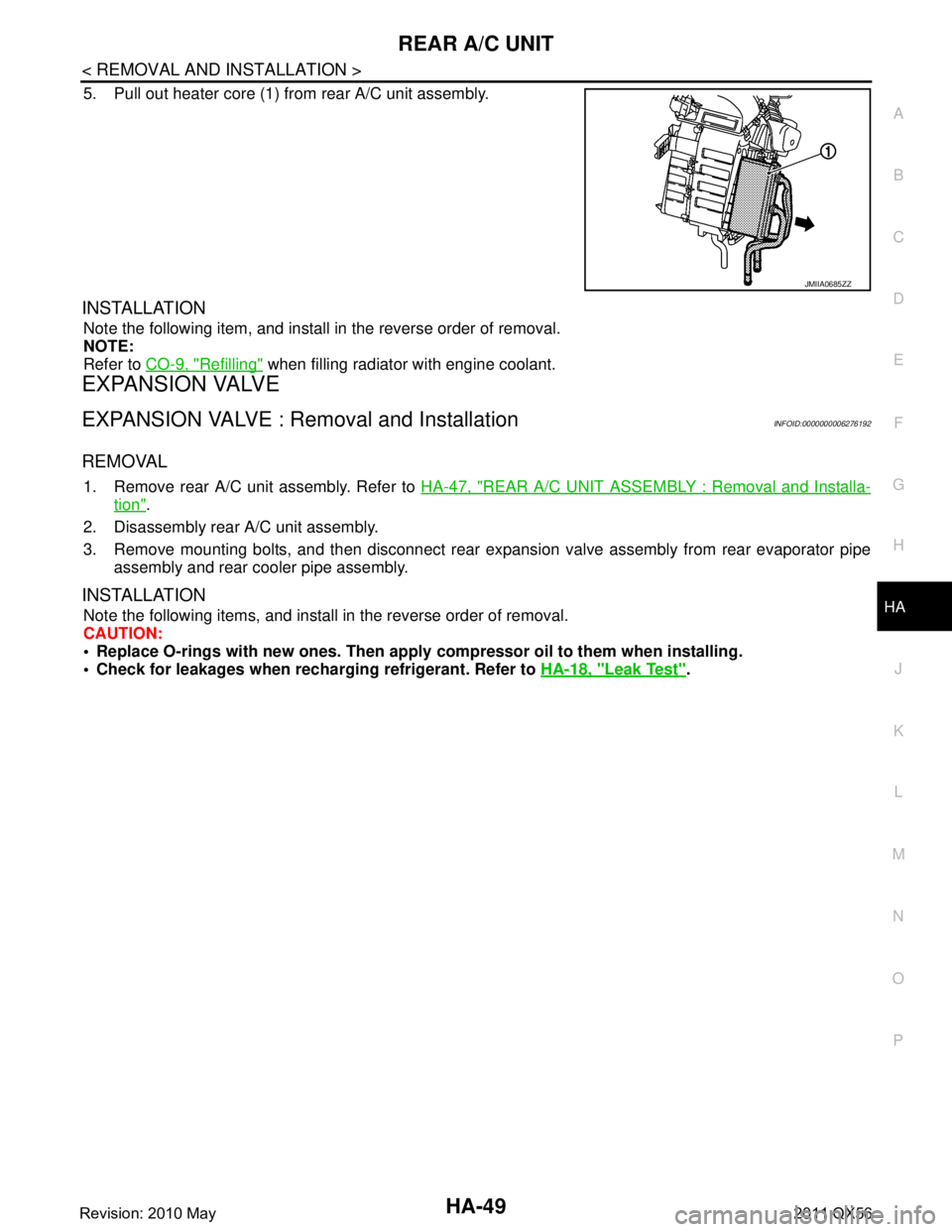
5. Pull out heater core (1) from rear A/C unit assembly.
INSTALLATION
Note the following item, and install in the reverse order of removal.
NOTE:
Refer to CO-9, "
Refilling" when filling radiator with engine coolant.
EXPANSION VALVE
EXPANSION VALVE : Removal and InstallationINFOID:0000000006276192
REMOVAL
1. Remove rear A/C unit assembly. Refer to HA-47, "REAR A/C UNIT ASSEMBLY : Removal and Installa-
tion".
2. Disassembly rear A/C unit assembly.
3. Remove mounting bolts, and then disconnect rear exp ansion valve assembly from rear evaporator pipe
assembly and rear cooler pipe assembly.
INSTALLATION
Note the following items, and install in the reverse order of removal.
CAUTION:
Replace O-rings with new ones. Then apply compressor oil to them when installing.
Check for leakages when recharging refrigerant. Refer to HA-18, "
Leak Test".
JMIIA0685ZZ
Revision: 2010 May2011 QX56
Page 3145 of 5598
![INFINITI QX56 2011 Factory Service Manual
DIAGNOSIS SYSTEM (HVAC)HAC-39
< SYSTEM DESCRIPTION > [AUTOMATIC AIR CONDITIONING]
C
D
E
F
G H
J
K L
M A
B
HAC
N
O P
DIAGNOSIS SYSTEM (HVAC)
DescriptionINFOID:0000000006275884
Air conditioning system INFINITI QX56 2011 Factory Service Manual
DIAGNOSIS SYSTEM (HVAC)HAC-39
< SYSTEM DESCRIPTION > [AUTOMATIC AIR CONDITIONING]
C
D
E
F
G H
J
K L
M A
B
HAC
N
O P
DIAGNOSIS SYSTEM (HVAC)
DescriptionINFOID:0000000006275884
Air conditioning system](/manual-img/42/57033/w960_57033-3144.png)
DIAGNOSIS SYSTEM (HVAC)HAC-39
< SYSTEM DESCRIPTION > [AUTOMATIC AIR CONDITIONING]
C
D
E
F
G H
J
K L
M A
B
HAC
N
O P
DIAGNOSIS SYSTEM (HVAC)
DescriptionINFOID:0000000006275884
Air conditioning system performs self-diagnosis, operat ion check, function diagnosis, and various settings
using diagnosis function of each control unit.
CONSULT-III FunctionINFOID:0000000006275885
CONSULT-III performs the following functions via CAN communication with A/C auto amp.
NOTE:
Diagnosis should be performed with engine running. D oor motor operation speeds become slower and NO
results may be returned even for normal operation if battery voltage drops below 12 V during self-diagnosis.
SELF-DIAGNOSIS RESULTS
Refer to HAC-45, "DTC Index".
DATA MONITOR
Display item list
ECU Diagnostic item
(CONSULT-III)
A/C auto amp. HVACSelf Diagnostic Result
Data Monitor
Active Test
Work support
AV c o n t r o l u n i t MULTI AV
Self Diagnostic Result
Multi AV system on board diagnosis function
ECM ENGINESelf Diagnostic Result
Data Monitor
IPDM E/R IPDM E/RSelf Diagnostic Result
Data Monitor
Auto active test
Diagnostic mode Description
Self diagnostic result Displays the diagnosis results judged by A/C auto amp.
Data monitor Displays the input/output signal of A/C auto amp.
Active test The signals used to activate each device are forcibly supplied from A/C auto amp.
Work support Changes the setting for each setting function.
ECU identification Displays the part number of A/C auto amp.
Monitor item [Unit] Description
AMB TEMP SEN [ °C ( °F)] Ambient sensor value converted from ambient sensor signal received from ambient sen-
sor
IN-VEH TEMP [ °C ( °F)] Front in-vehicle sensor value converted from front in-vehicle sensor signal received from
front in-vehicle sensor
INT TEMP SEN [ °C ( °F)] Intake sensor value converted from intake sensor signal received from intake sensor
SUNLOAD SEN [w/m
2]Sunload sensor value converted from sunload sensor signal (driver side) received from
sunload sensor
AMB SEN CAL [ °C ( °F)] Ambient temperature value calculated by A/C auto amp.
IN-VEH CAL [ °C ( °F)] In-vehicle temperature (front side) value calculated by A/C auto amp.
INT TEMP CAL [ °C ( °F)] Front evaporator fin temperature value calculated by A/C auto amp.
SUNL SEN CAL [w/m
2]Sunload value (driver side) calculated by A/C auto amp.
Revision: 2010 May2011 QX56