Page 3706 of 5598

MIR-1
DRIVER CONTROLS
C
DE
F
G H
I
J
K
M
SECTION MIR
A
B
MIR
N
O P
CONTENTS
MIRRORS
PRECAUTION ................ ...............................3
PRECAUTIONS .............................................. .....3
Precaution for Supplemental Restraint System
(SRS) "AIR BAG" and "SEAT BELT PRE-TEN-
SIONER" ............................................................. ......
3
Precaution Necessary for Steering Wheel Rota-
tion after Battery Disconnect .....................................
3
PREPARATION ............................................5
PREPARATION .............................................. .....5
Commercial Service Tools ................................. ......5
SYSTEM DESCRIPTION ..............................6
COMPONENT PARTS ................................... .....6
DOOR MIRROR ..................................................... ......6
DOOR MIRROR : Component Parts Location ..........6
DOOR MIRROR : Component Description ...............6
INSIDE MIRROR .................................................... ......7
INSIDE MIRROR : Component Description ..............7
SYSTEM ..............................................................8
DOOR MIRROR SYSTEM ..................................... ......8
DOOR MIRROR SYSTEM : System Diagram ..........8
DOOR MIRROR SYSTEM : System Description ......8
AUTO ANTI-DAZZLING INSIDE MIRROR SYS-
TEM ........................................................................ ......
9
AUTO ANTI-DAZZLING INSIDE MIRROR SYS-
TEM : System Description .........................................
9
ECU DIAGNOSIS INFORMATION ..............10
DRIVER SEAT CONTROL UNIT, AUTOMAT-
IC DRIVE POSITIONER CONTROL UNIT ..... ....
10
List of ECU Reference ........................................ ....10
WIRING DIAGRAM ......................................11
DOOR MIRROR SYSTEM .................................11
Wiring Diagram .................................................... ....11
AUTO ANTI-DAZZLING INSIDE MIRROR
SYSTEM ............................................................
19
Wiring Diagram - INSIDE MIRROR SYSTEM - ... ....19
BASIC INSPECTION ....... ............................21
DIAGNOSIS AND REPAIR WORKFLOW ........21
Work Flow ............................................................ ....21
DTC/CIRCUIT DIAGNOSIS .........................22
DOOR MIRROR REMOTE CONTROL
SWITCH .............................................................
22
OPEN/CLOSE SWITCH ......................................... ....22
OPEN/CLOSE SWITCH : Component Inspection ....22
SYMPTOM DIAGNOSIS ..............................23
REVERSE INTERLOCK DOOR MIRROR
DOES NOT OPERATE ......................................
23
Diagnosis Procedure ........................................... ....23
SQUEAK AND RATTLE TROUBLE DIAG-
NOSES ..............................................................
24
Work Flow ................................................................24
Inspection Procedure ...............................................26
Diagnostic Worksheet ..............................................28
REMOVAL AND INSTALLATION ...............30
INSIDE MIRROR ...............................................30
Exploded View ..................................................... ....30
Removal and Installation .........................................30
OUTSIDE MIRROR ...........................................32
Exploded View .........................................................32
DOOR MIRROR ASSEMBLY ....................................32
Revision: 2010 May2011 QX56
Page 3707 of 5598
MIR-2
DOOR MIRROR ASSEMBLY : Removal and In-
stallation .................................................................
32
DOOR MIRROR ASSEMBLY : Disassembly and
Assembly ............................................................. ...
33
GLASS MIRROR .................................................... ...35
GLASS MIRROR : Removal and Installation ..........35
DOOR MIRROR COVER ........................................ ...35
DOOR MIRROR COVER : Removal and Installa-
tion ..........................................................................
36
SIDE CAMERA FINISHER ASSEMBLY ...................36
SIDE CAMERA FINISHER ASSEMBLY : Remov-
al and Installation ................................................. ...
36
DOOR MIRROR REMOTE CONTROL
SWITCH .............................................................
38
Removal and Installation ...................................... ...38
Revision: 2010 May2011 QX56
Page 3711 of 5598

MIR-6
< SYSTEM DESCRIPTION >
COMPONENT PARTS
SYSTEM DESCRIPTION
COMPONENT PARTS
DOOR MIRROR
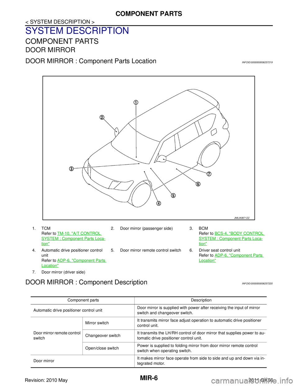
DOOR MIRROR : Component Parts LocationINFOID:0000000006257219
DOOR MIRROR : Component DescriptionINFOID:0000000006257220
1. TCMRefer to TM-10, "
A/T CONTROL
SYSTEM : Componen t Parts Loca-
tion"
2. Door mirror (passenger side) 3. BCM
Refer to BCS-4, "
BODY CONTROL
SYSTEM : Component Parts Loca-
tion"
4. Automatic drive positioner control
unit
Refer to ADP-6, "
Component Parts
Location"
5. Door mirror remote control switch 6. Driver seat control unit
Refer to ADP-6, "
Component Parts
Location"
7. Door mirror (driver side)
JMLIA0871ZZ
Component parts Description
Automatic drive positioner control unit Door mirror is supplied with power after receiving the input of mirror
switch and changeover switch.
Door mirror re mote control
switch Mirror switch
It transmits mirror face adjust operation to automatic drive positioner
control unit.
Changeover switch It transmits the LH/RH control of door mirror that supplies power to au-
tomatic drive positioner control unit.
Open/close switch Power is supplied to folding mirro
r from door mirror remote control
switch when operating switch.
Door mirror It makes mirror face operate from side to side and up and down via in-
tegrated motor.
Revision: 2010 May2011 QX56
Page 3713 of 5598

MIR-8
< SYSTEM DESCRIPTION >
SYSTEM
SYSTEM
DOOR MIRROR SYSTEM
DOOR MIRROR SYSTEM : System DiagramINFOID:0000000006257222
DOOR MIRROR SYSTEM : System DescriptionINFOID:0000000006257223
MANUAL FUNCTION
Description
Automatic drive positioner control unit controls door mirror.
Automatic drive positioner control unit inputs changeover switch signal and perform the LH/RH control of
door mirror motor supplying electric power when changeover switch is operated.
Automatic drive positioner control unit inputs mirror s witch signal and supplies electric power to door mirror.
The ignition switch signal (ACC/ON) is transmitted from BCM to driver seat control unit via CAN communica-
tion and from driver seat control unit to automatic drive positioner control unit via UART communication.
Operation Conditions
If the following conditions are not satisfied, operation is not performed.
Ignition switch: ON or ACC
Changeover switch: Select either left or right
REVERSE INTERLOCK DOOR MIRROR SYSTEM
Description
Select either of the door mirror faces by changeover switch, and then set mirror face downward.
When ignition switch is ON position and A/T shift selector is in R position, TCM sends the R signal to driver
seat control unit.
The R signal is transmitted to automatic drive positioner control unit from driver seat control unit via UART
communication.
When the R signal is detected, automatic drive positioner control unit activated mirror motor.
Operation Conditions
If the following conditions are not satisfied, operation is not performed.
Ignition switch: ON
JMLIA0872GB
Revision: 2010 May2011 QX56
Page 3714 of 5598
SYSTEMMIR-9
< SYSTEM DESCRIPTION >
C
DE
F
G H
I
J
K
M A
B
MIR
N
O P
Changeover switch: Select either left or right
A/T shift selector: R position
NOTE:
During the reverse interlock door mirror system, if all of the above conditions are not satisfied, mirror face
returns to original angle.
AUTO ANTI-DAZZLING INSIDE MIRROR SYSTEM
AUTO ANTI-DAZZLING INSIDE MIRRO R SYSTEM : System DescriptionINFOID:0000000006257224
The sensor built in inside mirror detects the bri ghtness of headlight of the vehicle behind and automatically
changes the light transmission to decrease the brightness.
Revision: 2010 May2011 QX56
Page 3716 of 5598
DOOR MIRROR SYSTEMMIR-11
< WIRING DIAGRAM >
C
DE
F
G H
I
J
K
M A
B
MIR
N
O P
WIRING DIAGRAM
DOOR MIRROR SYSTEM
Wiring DiagramINFOID:0000000006257226
JCLWM5426GB
Revision: 2010 May2011 QX56
Page 3717 of 5598
MIR-12
< WIRING DIAGRAM >
DOOR MIRROR SYSTEM
JCLWM5427GB
Revision: 2010 May2011 QX56
Page 3718 of 5598
DOOR MIRROR SYSTEMMIR-13
< WIRING DIAGRAM >
C
DE
F
G H
I
J
K
M A
B
MIR
N
O P
JCLWM5428GB
Revision: 2010 May2011 QX56