2011 INFINITI QX56 door
[x] Cancel search: doorPage 3750 of 5598

MWI
COMPONENT PARTSMWI-7
< SYSTEM DESCRIPTION >
C
DE
F
G H
I
J
K L
M B A
O P
METER SYSTEM : Com ponent DescriptionINFOID:0000000006221691
CLOCK
Unit Description
Combination meter Controls the following with the signals received from each unit via CAN communication and the sig-
nals from switches and sensors.
Speedometer
Tachometer
Engine coolant temperature gauge
Fuel gauge
Engine oil pressure gauge
Voltmeter
Warning lamps
Indicator lamps
Meter illumination control
Meter effect function
Information display
Trip computer switch Transmits the following signals to the combination meter.
Enter switch signal
Select switch signal
Trip reset and illumination con-
trol switch Transmits the following signals to the combination meter.
Trip reset switch signal
Illumination control switch signal (+)
Illumination control switch signal (
−)
ECM Transmits the following signals to the combination meter via CAN communication.
Engine speed signal
Engine coolant temperature signal
Engine status signal
Fuel consumption monitor signal
ABS actuator and electric unit
(control unit) Transmits the vehicle speed signal to the combination meter via CAN communication.
IPDM E/R Transmits the oil pressure switch signal to the BCM via CAN communication.
BCM Transmits the following signals to the combination meter via CAN communication.
Oil pressure switch signal
Position light request signal
Dimmer signal
Door switch signal
Meter ring illumination request signal
Starter relay status signal
TCM Transmits the shift position signal to the combination meter via CAN communication.
A/T shift selector Transmits the following signals to the combination meter.
Manual mode signal
Non-manual mode signal
Manual mode shift up signal
Manual mode shift down signal
Fuel level sensor unit Transmits the fuel level sensor signal to the combination meter.
Oil pressure switch Transmits the oil pressure switch signal to the IPDM E/R.
Ambient sensor Transmits the ambient sensor signal to the combination meter.
A/C auto amp. Transmits the A/C auto amp. connection recognition signal to the combination meter.
Parking brake switch Transmits the parking brake switch signal to the combination meter.
Washer level switch Transmits the washer level switch signal to the combination meter.
Revision: 2010 May2011 QX56
Page 3754 of 5598
MWI
SYSTEMMWI-11
< SYSTEM DESCRIPTION >
C
DE
F
G H
I
J
K L
M B A
O P
ARRANGEMENT OF COMBINATION METER
Information
display Odo/trip meter Displays mileage.
MWI-20, "
INFOR-
MATION DIS-
PLAY : System
Description"
Shift position indicator Displays shift position.
Trip computerCurrent fuel consumption Displays current fuel consumption.
Average fuel consumption Displays average fuel consumption.
Distance to empty Displays distance to empty.
Average vehicle speed Displays average vehicle speed.
Travel time Displays travel time.
Travel distance Displays mileage.
Ambient temperature Displays ambient temperature.
Interrupt indi-
cation Warning
Door open
warning
Warns when a door is open.
Parking brake
release warning Warns if traveling when the parking brake is
under operating condition.
Low fuel warn-
ing Warns when being low on fuel.
Low washer flu-
id warning Displayed/Hidden, depending on washer
fluid level.
Alert Travel time
Causes an interrupt when exceeding ran-
domly set time.
Low ambient
temperature Causes an interrupt when ambient tempera-
ture reaches below 3
°C (37 °F).
Maintenance Tire
Causes an interrupt when exceeding ran-
domly set distance.
Oil filter Causes an interrupt when exceeding ran-
domly set distance.
Engine oil Causes an interrupt when exceeding ran-
domly set distance.
Other Causes an interrupt when exceeding ran-
domly set distance.
Meter illumination level Indicates the brightness of the meter illumi-
nation in stages.
Setting Alert
Timer
Allows the user to set a display time for
“Travel time”.
ICY Allows the ON/OFF setting of the low ambi-
ent temperature (alert) function.
Maintenance Tire
Alerts when reaching mileage set in “SET-
TING”.
Filter Alerts when reaching mileage set in “SET-
TING”.
Oil Alerts when reaching mileage set in “SET-
TING”.
Other Alerts when reaching mileage set in “SET-
TING”.
Options Language
Allows the user to set language for informa-
tion display.
Unit Allows unit settings.
Effects Allows the ON/OFF setting of the engine-
start effect function.
System Description Reference
Revision: 2010 May2011 QX56
Page 3755 of 5598
MWI-12
< SYSTEM DESCRIPTION >
SYSTEM
METER SYSTEM : Fail-Safe
INFOID:0000000006221695
FA I L - S A F E
The combination meter activates the fail-safe contro l if CAN communication with each unit is malfunctioning.
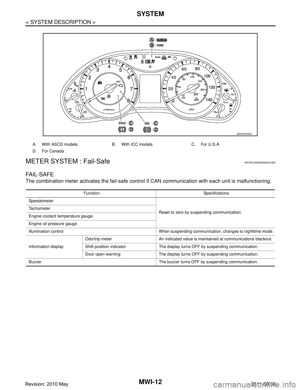
A. With ASCD models B. With ICC models C. For U.S.A.
D. For Canada
JSNIA3234ZZ
Function Specifications
Speedometer
Reset to zero by suspending communication.
Tachometer
Engine coolant temperature gauge
Engine oil pressure gauge
Illumination control When suspending communication, changes to nighttime mode.
Information display Odo/trip meter An indicated value is maintained at communications blackout.
Shift position indicator The display turns OFF by suspending communication.
Door open warning The display turns OFF by suspending communication.
Buzzer The buzzer turns OFF by suspending communication.
Revision: 2010 May2011 QX56
Page 3759 of 5598
MWI-16
< SYSTEM DESCRIPTION >
SYSTEM
OIL PRESSURE WARNING LAMP : System Description
INFOID:0000000006221709
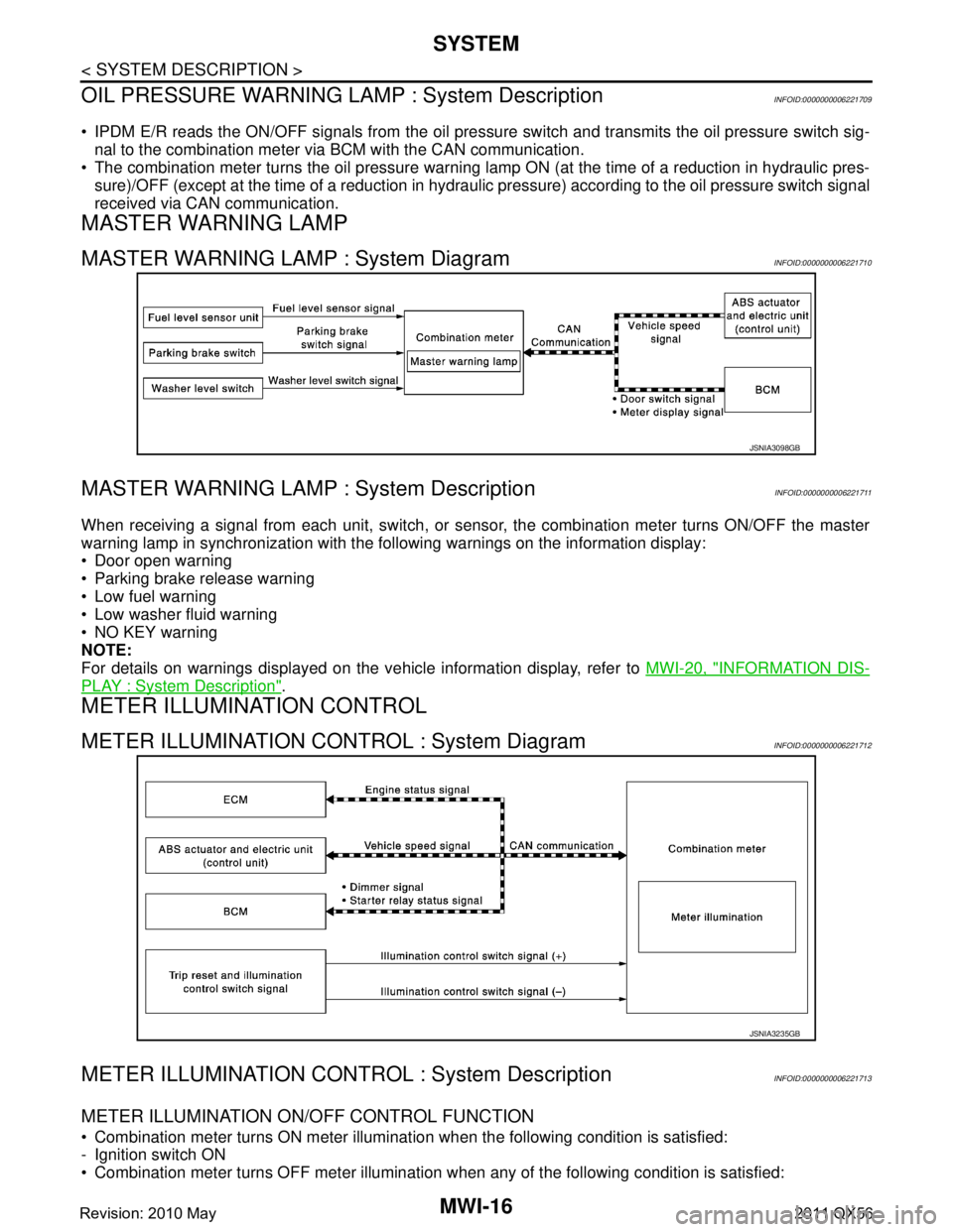
IPDM E/R reads the ON/OFF signals fr om the oil pressure switch and transmits the oil pressure switch sig-
nal to the combination meter via BCM with the CAN communication.
The combination meter turns the oil pressure warning lamp ON (at the time of a reduction in hydraulic pres-
sure)/OFF (except at the time of a reduction in hydraulic pressure) according to the oil pressure switch signal
received via CAN communication.
MASTER WARNING LAMP
MASTER WARNING LAMP : System DiagramINFOID:0000000006221710
MASTER WARNING LAMP : System DescriptionINFOID:0000000006221711
When receiving a signal from each unit, switch, or s ensor, the combination meter turns ON/OFF the master
warning lamp in synchronization with the following warnings on the information display:
Door open warning
Parking brake release warning
Low fuel warning
Low washer fluid warning
NO KEY warning
NOTE:
For details on warnings displayed on the vehicle information display, refer to MWI-20, "
INFORMATION DIS-
PLAY : System Description".
METER ILLUMINATION CONTROL
METER ILLUMINATION CONTROL : System DiagramINFOID:0000000006221712
METER ILLUMINATION CONTRO L : System DescriptionINFOID:0000000006221713
METER ILLUMINATION ON/OFF CONTROL FUNCTION
Combination meter turns ON meter illumination when the following condition is satisfied:
- Ignition switch ON
Combination meter turns OFF meter illumination when any of the following condition is satisfied:
JSNIA3098GB
JSNIA3235GB
Revision: 2010 May2011 QX56
Page 3760 of 5598
MWI
SYSTEMMWI-17
< SYSTEM DESCRIPTION >
C
DE
F
G H
I
J
K L
M B A
O P
- During a crank with vehicle speed less than 1 km/h (0.6 MPH)
- Ignition switch OFF or ACC
The combination meter receives the following signals to control meter illumination.
METER ILLUMINATION CONTROL FUNCTION
The combination meter controls meter illumination, based on the following signal.
- Dimmer signal
The combination meter switches mode between Daytim e mode and Nighttime mode, according to the fol-
lowing conditions.
*: For further information, refer to INL-11, "
AUTO LIGHT ADJUSTMENT SYSTEM : System Description".
The operation of the illumination control switch allo ws the brightness adjustment of meter illumination.
METER EFFECT FUNCTION
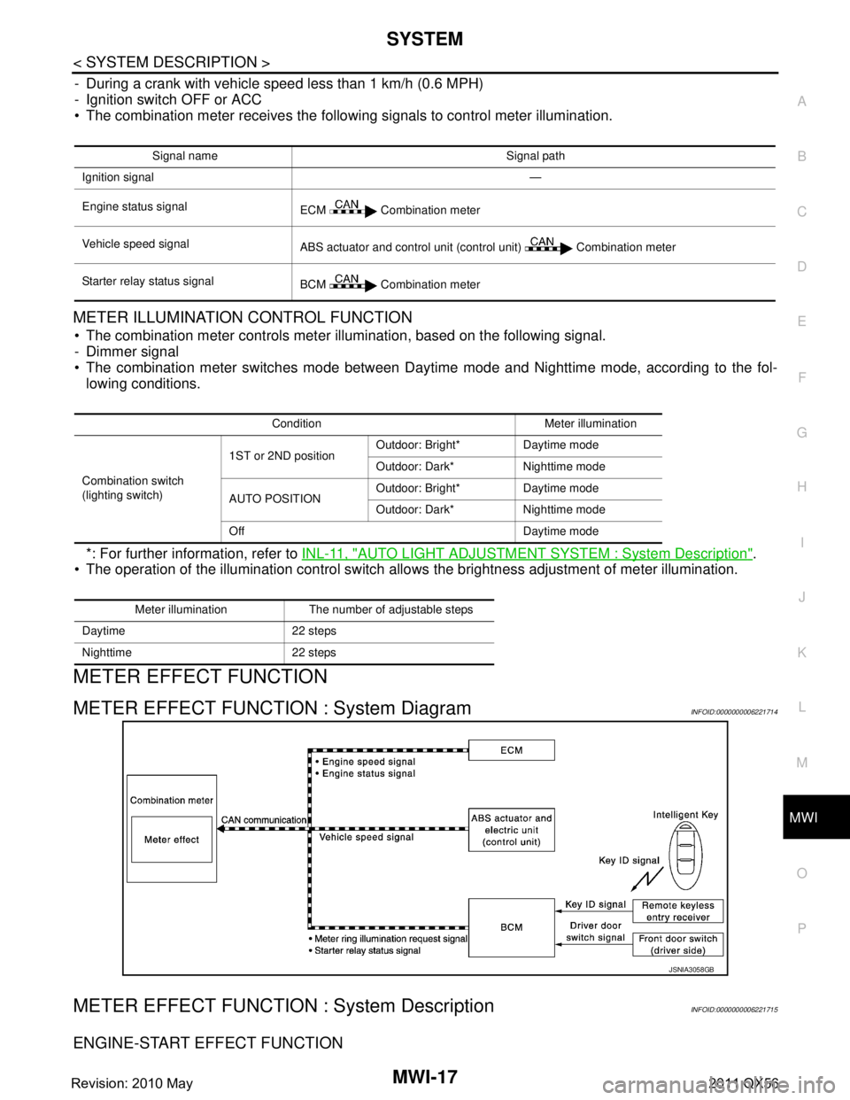
METER EFFECT FUNCTION : System DiagramINFOID:0000000006221714
METER EFFECT FUNCTION : System DescriptionINFOID:0000000006221715
ENGINE-START EFFECT FUNCTION
Signal name Signal path
Ignition signal —
Engine status signal ECM Combination meter
Vehicle speed signal ABS actuator and control unit (control unit) Combination meter
Starter relay status signal BCM Combination meter
Condition Meter illumination
Combination switch
(lighting switch) 1ST or 2ND position
Outdoor: Bright* Daytime mode
Outdoor: Dark* Nighttime mode
AUTO POSITION Outdoor: Bright* Daytime mode
Outdoor: Dark* Nighttime mode
Off Daytime mode
Meter illumination The number of adjustable steps
Daytime 22 steps
Nighttime 22 steps
JSNIA3058GB
Revision: 2010 May2011 QX56
Page 3762 of 5598
MWI
SYSTEMMWI-19
< SYSTEM DESCRIPTION >
C
DE
F
G H
I
J
K L
M B A
O P
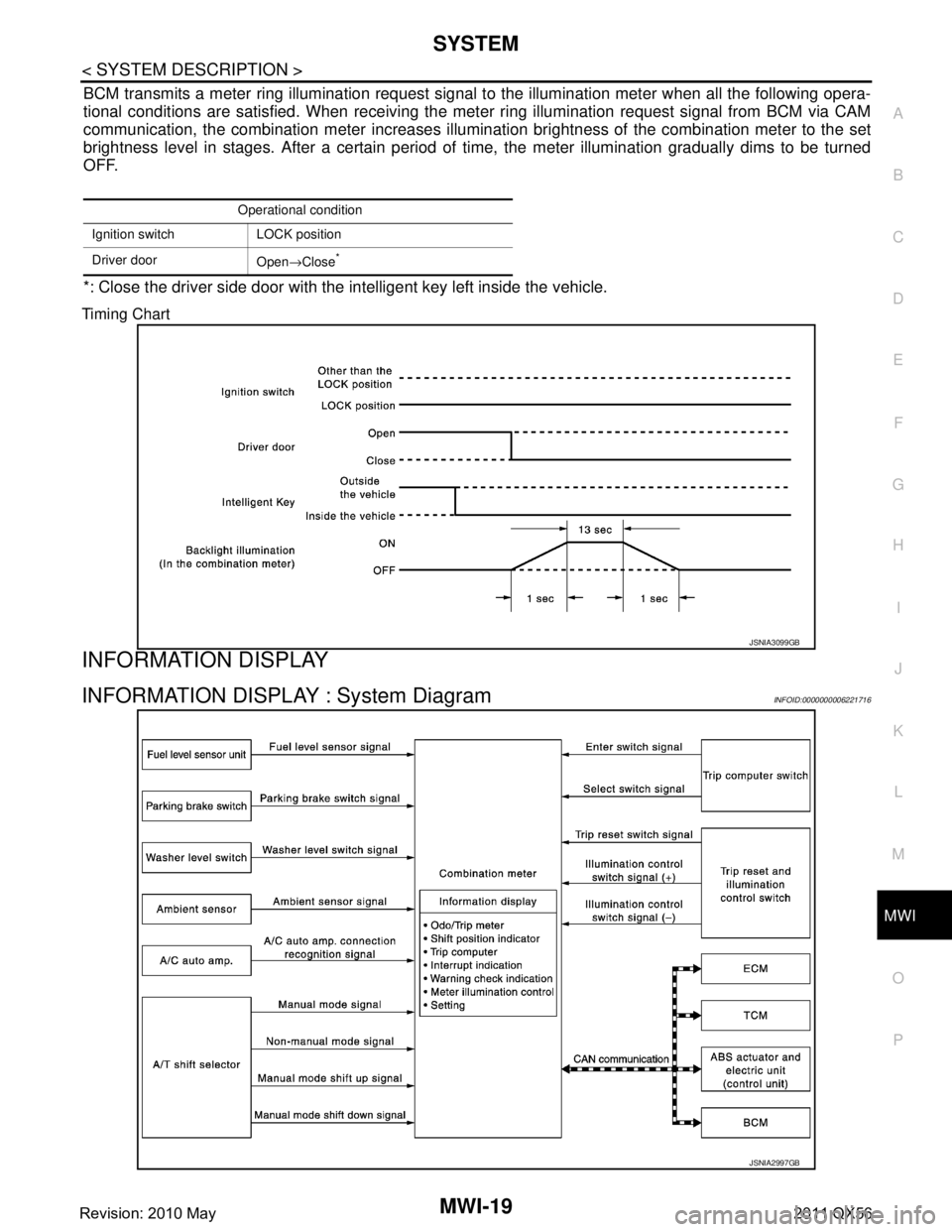
BCM transmits a meter ring illumination request signal to the illumination meter when all the following opera-
tional conditions are satisfied. When receiving the meter ring illumination request signal from BCM via CAM
communication, the combination meter increases illuminat ion brightness of the combination meter to the set
brightness level in stages. After a certain period of time, the meter illumination gradually dims to be turned
OFF.
*: Close the driver side door with the intelligent key left inside the vehicle.
Timing Chart
INFORMATION DISPLAY
INFORMATION DISPLAY : System DiagramINFOID:0000000006221716
Operational condition
Ignition switch LOCK position
Driver door Open→Close
*
JSNIA3099GB
JSNIA2997GB
Revision: 2010 May2011 QX56
Page 3766 of 5598
MWI
SYSTEMMWI-23
< SYSTEM DESCRIPTION >
C
DE
F
G H
I
J
K L
M B A
O P
The ambient sensor input value that is displayed on “Data Monitor” of CONSULT-III is the value before the
correction. It may not match the indica ted temperature on the information display.
After removal and installation of the battery and comb ination meter, an ambient sensor-detected tempera-
ture is indicated on the information display.
Depending on engine heat or heat on the road surfaces, an ambient temperature may be indicated higher
than actual one.
INTERRUPT INDICATION
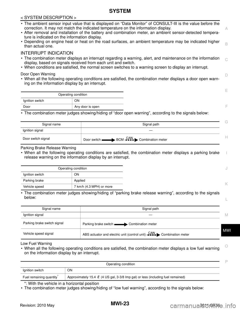
The combination meter displays an interrupt regarding a warning, alert, and maintenance on the information
display, based on signals received from each unit and switch.
When conditions are satisfied, the normal screen swit ches to a warning screen to display an interrupt.
Door Open Warning
When all the following operating conditions are satisfied, the combination meter displays a door open warn-
ing on the information display by an interrupt.
The combination meter judges showing/hiding of “door open warning”, according to the signals below:
Parking Brake Release Warning
When all the following operating conditions are satisfi ed, the combination meter displays a parking brake
release warning on the information display by an interrupt.
The combination meter judges showing/hiding of “parki ng brake release warning”, according to the signals
below:
Low Fuel Warning
When all the following operating conditions are satisfied, the combination meter displays a low fuel warning on the information display by an interrupt.
*: With the vehicle in a horizontal position
The combination meter judges showing/hiding of “low fuel warning”, according to the signals below:
Operating condition
Ignition switch ON
Door Any door is open
Signal name Signal path
Ignition signal —
Door switch signal Door switch BCM Combination meter
Operating condition
Ignition switch ON
Parking brake Applied
Vehicle speed 7 km/h (4.3 MPH) or more
Signal name Signal path
Ignition signal —
Parking brake switch signal Parking brake switch Combination meter
Vehicle speed signal ABS actuator and electric unit (control unit) Combination meter
Operating condition
Ignition switch ON
Fuel remaining quantity
*Approximately 15.4 (4 US gal, 3-3/8 Imp gal) or less (including fuel remained)
Revision: 2010 May2011 QX56
Page 3774 of 5598
![INFINITI QX56 2011 Factory Service Manual
MWI
DIAGNOSIS SYSTEM (COMBINATION METER)
MWI-31
< SYSTEM DESCRIPTION >
C
D E
F
G H
I
J
K L
M B A
O P
W TEMP METER
[ ° C] XValue of engine coolant temperature signal is received from ECM via CAN com INFINITI QX56 2011 Factory Service Manual
MWI
DIAGNOSIS SYSTEM (COMBINATION METER)
MWI-31
< SYSTEM DESCRIPTION >
C
D E
F
G H
I
J
K L
M B A
O P
W TEMP METER
[ ° C] XValue of engine coolant temperature signal is received from ECM via CAN com](/manual-img/42/57033/w960_57033-3773.png)
MWI
DIAGNOSIS SYSTEM (COMBINATION METER)
MWI-31
< SYSTEM DESCRIPTION >
C
D E
F
G H
I
J
K L
M B A
O P
W TEMP METER
[ ° C] XValue of engine coolant temperature signal is received from ECM via CAN com-
munication.
NOTE:
215 is displayed when the malfunction signal is input.
ABS W/L
[On/Off] Status of ABS warning lamp detected fr
om ABS warning lamp signal is received
from ABS actuator and electric unit (control unit) via CAN communication.
VDC/TCS IND
[On/Off] Status of VDC OFF indicator lamp detected from VDC OFF indicator lamp signal
is received from ABS actuator
and electric unit (control unit) via CAN communica-
tion.
SLIP IND
[On/Off] Status of VDC warning lamp detected from VDC warning lamp signal received
from ABS actuator and electric unit (control unit) via CAN communication.
BRAKE W/L
[On/Off] Status of brake warning lamp detected from brake warning lamp signal is received
from ABS actuator and electric unit (control unit) via CAN communication.
NOTE:
Displays “Off” if the brake warning lamp is illuminated when the valve check starts,
the parking brake switch is turned ON or the brake fluid level switch is turned ON.
DOOR W/L
[On/Off] Status of door open warning detected from door switch signal received from BCM
via CAN communication.
HI-BEAM IND
[On/Off] Status of high beam indicator lamp detected from high beam request signal is re-
ceived from BCM via CAN communication.
TURN IND
[On/Off] Status of turn indicator lamp detected from turn indicator signal is received from
BCM via CAN communication.
FR FOG IND
[Off] This item is displayed, but cannot be monitored.
RR FOG IND
[Off] This item is displayed, but cannot be monitored.
LIGHT IND
[On/Off] Status of light indicator lamp detected from position light request signal is received
from BCM via CAN communication.
OIL W/L
[On/Off] Status of oil pressure warning lamp detected from oil pressure switch signal is re-
ceived from BCM via CAN communication.
MIL
[On/Off] Status of malfunction indicator lamp detected from malfunctioning indicator lamp
signal is received from ECM via CAN communication.
GLOW IND
[Off] This item is displayed, but cannot be monitored.
CRUISE IND
[On/Off] Status of CRUISE indicator detected from ASCD status signal is received from
ECM via CAN communicat ion. (ASCD models)
Status of CRUISE indicator de tected from meter display signal is received from
ADAS control unit via CAN communication. (ICC models)
SET IND
[On/Off] Status of SET indicator detected from meter display signal is received from ADAS
control unit via CAN communication.
CRUISE W/L
[On/Off] Status of CRUISE warning lamp
judged from ICC warning lamp signal received
from ADAS control unit with CAN communication line.
BA W/L
[On/Off] Status of IBA OFF indicator lamp judged from IBA OFF indicator lamp signal re-
ceived from ADAS control unit with CAN communication line.
ATC/T-AMT W/L
[On/Off] Status of A/T CHECK warning lamp judged
from A/T CHECK indicator lamp signal
received from TCM with CAN communication line.
ATF TEMP W/L
[Off] This item is displayed, but cannot be monitored.
4WD W/L
[On/Off] Status of 4WD warning lamp judged from 4WD warning lamp signal received from
4WD control unit with
CAN communication line.
FUEL W/L
[On/Off] Low-fuel warning lamp status detected by the identified fuel level.
WASHER W/L
[On/Off] Status of low washer fluid warning judged from washer level switch input to com-
bination meter.
Display item [Unit]
MAIN
SIGNALS Description
Revision: 2010 May2011 QX56