2011 INFINITI QX56 roof
[x] Cancel search: roofPage 3359 of 5598
INT-10
< SYMPTOM DIAGNOSIS >
SQUEAK AND RATTLE TROUBLE DIAGNOSES
1. Trunk lid dumpers out of adjustment
2. Trunk lid striker out of adjustment
3. Trunk lid torsion bars knocking together
4. A loose license plate or bracket
Most of these incidents can be repaired by adjusting, securing, or insulating the item(s) or component(s) caus-
ing the noise.
SUNROOF/HEADLINING
Noises in the sunroof / headlining area can often be traced to one of the following items:
1. Sunroof lid, rail, linkage, or seals making a rattle or light knocking noise
2. Sunvisor shaft shaking in the holder
3. Front or rear windshield touching headlining and squeaking
Again, pressing on the components to stop the noise while duplicating the conditions can isolate most of these
incidents. Repairs usually consist of insulating with felt cloth tape.
SEATS
When isolating seat noise it is important to note t he position the seat is in and the load placed on the seat
when the noise occurs. These conditions should be duplic ated when verifying and isolating the cause of the
noise.
Causes of seat noise include:
1. Headrest rods and holder
2. A squeak between the seat pad cushion and frame
3. The rear seatback lock and bracket
These noises can be isolated by moving or pressing on the suspected components while duplicating the con-
ditions under which the noise occurs. Most of thes e incidents can be repaired by repositioning the component
or applying urethane tape to the contact area.
UNDERHOOD
Some interior noise may be caused by components under the hood or on the engine wall. The noise is then
transmitted into the passenger compartment.
Causes of transmitted underhood noise include:
1. Any component mounted to the engine wall
2. Components that pass through the engine wall
3. Engine wall mounts and connectors
4. Loose radiator mounting pins
5. Hood bumpers out of adjustment
6. Hood striker out of adjustment
These noises can be difficult to isolate since they cannot be reached from the interior of the vehicle. The best
method is to secure, move, or insulate one component at a time and test drive the vehicle. Also, engine RPM
or load can be changed to isolate the noise. Repairs can usually be made by moving, adjusting, securing, or
insulating the component causing the noise.
Revision: 2010 May2011 QX56
Page 3378 of 5598
HEADLININGINT-29
< REMOVAL AND INSTALLATION >
C
DE
F
G H
I
K L
M A
B
INT
N
O P
Removal and InstallationINFOID:0000000006220257
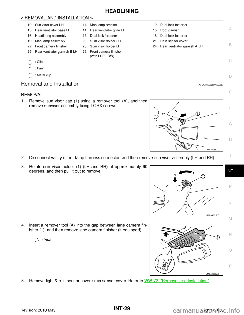
REMOVAL
1. Remove sun visor cap (1) using a remover tool (A), and then remove sunvisor assembly fixing TORX screws.
2. Disconnect vanity mirror lamp harness connector, and then remove sun visor assembly (LH and RH).
3. Rotate sun visor holder (1) (LH and RH) at approximately 90 degrees, and then pull it out to remove.
4. Insert a remover tool (A) into the gap between lane camera fin- isher (1), and then remove lane camera finisher (if equipped).
5. Remove light & rain sensor cover / rain sensor cover. Refer to WW-72, "
Removal and Installation".
10. Sun visor cover LH 11. Map lamp bracket 12. Dual lock fastener
13. Rear ventilator base LH 14. Rear ventilator grille LH 15. Roof garnish
16. Headlining assembly 17. Dual lock fastener 18. Dual lock fastener
19. Map lamp assembly 20. Sum visor holder RH 21. Rain sensor cover
22. Front camera finisher 23. Sum visor holder LH 24. Rear ventilator garnish A LH
25. Rear ventilator garnish B LH 26. Front camera finisher
(with LDP/LDW)
: Clip
: Pawl
: Metal clip
JMJIA4055ZZ
JMJIA4061ZZ
: Pawl
JMJIA4053ZZ
Revision: 2010 May2011 QX56
Page 3379 of 5598
INT-30
< REMOVAL AND INSTALLATION >
HEADLINING
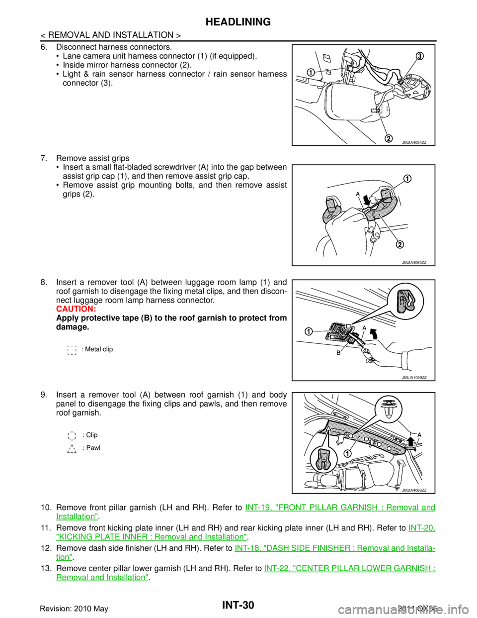
6. Disconnect harness connectors. Lane camera unit harness connector (1) (if equipped).
Inside mirror harness connector (2).
Light & rain sensor harness connector / rain sensor harness
connector (3).
7. Remove assist grips Insert a small flat-bladed screwdriver (A) into the gap between
assist grip cap (1), and then remove assist grip cap.
Remove assist grip mounting bolts, and then remove assist grips (2).
8. Insert a remover tool (A) between luggage room lamp (1) and roof garnish to disengage the fixing metal clips, and then discon-
nect luggage room lamp harness connector.
CAUTION:
Apply protective tape (B) to the roof garnish to protect from
damage.
9. Insert a remover tool (A) between roof garnish (1) and body panel to disengage the fixing clips and pawls, and then remove
roof garnish.
10. Remove front pillar garnish (LH and RH). Refer to INT-19, "
FRONT PILLAR GARNISH : Removal and
Installation".
11. Remove front kicking plate inner (LH and RH) and rear kicking plate inner (LH and RH). Refer to INT-20,
"KICKING PLATE INNER : Removal and Installation".
12. Remove dash side finisher (LH and RH). Refer to INT-18, "
DASH SIDE FINISHER : Removal and Installa-
tion".
13. Remove center pillar lower garnish (LH and RH). Refer to INT-22, "
CENTER PILLAR LOWER GARNISH :
Removal and Installation".
JMJIA4054ZZ
JMJIA4063ZZ
: Metal clip
JMLIA1059ZZ
: Clip
: Pawl
JMJIA4066ZZ
Revision: 2010 May2011 QX56
Page 3380 of 5598
HEADLININGINT-31
< REMOVAL AND INSTALLATION >
C
DE
F
G H
I
K L
M A
B
INT
N
O P
14. Remove luggage side lower finisher (LH and RH). Refer to INT-36, "LUGGAGE SIDE LOWER FINISHER
: Removal and Installation".
15. Remove front body side welt (LH and RH) and rear body side welt (LH and RH). Refer to INT-20, "
BODY
SIDE WELT : Removal and Installation".
16. Remove center pillar upper garnish (LH and RH). Refer to INT-22, "
CENTER PILLAR UPPER GARNISH :
Removal and Installation".
17. Remove rear pillar finisher (LH and RH). Refer to INT-37, "
REAR PILLAR FINISHER : Removal and
Installation".
18. Remove back pillar garnish (LH and RH). Refer to INT-37, "
BACK PILLAR GARNISH : Removal and
Installation".
19. Remove luggage side upper finisher (LH and RH). Refer to INT-38, "
LUGGAGE SIDE UPPER FINISHER
: Removal and Installation".
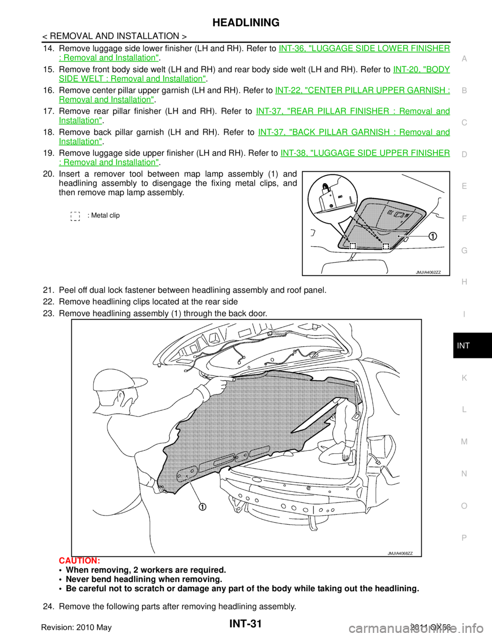
20. Insert a remover tool between map lamp assembly (1) and headlining assembly to disengage the fixing metal clips, and
then remove map lamp assembly.
21. Peel off dual lock fastener between headlining assembly and roof panel.
22. Remove headlining clips located at the rear side
23. Remove headlining assembly (1) through the back door.
CAUTION:
When removing, 2 workers are required.
Never bend headlini ng when removing.
Be careful not to scratch or damage any part of the body while taking out the headlining.
24. Remove the following parts after removing headlining assembly.
: Metal clip
JMJIA4062ZZ
JMJIA4068ZZ
Revision: 2010 May2011 QX56
Page 3400 of 5598
IP-10
< SYMPTOM DIAGNOSIS >
SQUEAK AND RATTLE TROUBLE DIAGNOSES
1. Trunk lid dumpers out of adjustment
2. Trunk lid striker out of adjustment
3. Trunk lid torsion bars knocking together
4. A loose license plate or bracket
Most of these incidents can be repaired by adjusting, securing, or insulating the item(s) or component(s) caus-
ing the noise.
SUNROOF/HEADLINING
Noises in the sunroof / headlining area can often be traced to one of the following items:
1. Sunroof lid, rail, linkage, or seals making a rattle or light knocking noise
2. Sunvisor shaft shaking in the holder
3. Front or rear windshield touching headlining and squeaking
Again, pressing on the components to stop the noise while duplicating the conditions can isolate most of these
incidents. Repairs usually consist of insulating with felt cloth tape.
SEATS
When isolating seat noise it is important to note t he position the seat is in and the load placed on the seat
when the noise occurs. These conditions should be duplic ated when verifying and isolating the cause of the
noise.
Causes of seat noise include:
1. Headrest rods and holder
2. A squeak between the seat pad cushion and frame
3. The rear seatback lock and bracket
These noises can be isolated by moving or pressing on the suspected components while duplicating the con-
ditions under which the noise occurs. Most of thes e incidents can be repaired by repositioning the component
or applying urethane tape to the contact area.
UNDERHOOD
Some interior noise may be caused by components under the hood or on the engine wall. The noise is then
transmitted into the passenger compartment.
Causes of transmitted underhood noise include:
1. Any component mounted to the engine wall
2. Components that pass through the engine wall
3. Engine wall mounts and connectors
4. Loose radiator mounting pins
5. Hood bumpers out of adjustment
6. Hood striker out of adjustment
These noises can be difficult to isolate since they cannot be reached from the interior of the vehicle. The best
method is to secure, move, or insulate one component at a time and test drive the vehicle. Also, engine RPM
or load can be changed to isolate the noise. Repairs can usually be made by moving, adjusting, securing, or
insulating the component causing the noise.
Revision: 2010 May2011 QX56
Page 3732 of 5598
SQUEAK AND RATTLE TROUBLE DIAGNOSESMIR-27
< SYMPTOM DIAGNOSIS >
C
DE
F
G H
I
J
K
M A
B
MIR
N
O P
Most of these incidents can be repaired by adjusting, securing or insulatingthe item(s) or component(s) caus-
ing the noise.
SUNROOF/HEADLINING
Noises in the sunroof/headlining area can often be traced to one of the following:
1. Sunroof lid, rail, linkage or seals making a rattle or light knockingnoise
2. Sunvisor shaft shaking in the holder
3. Front or rear windshield touching headlining and squeaking
Again, pressing on the components to stop the noise whil e duplicatingthe conditions can isolate most of these
incidents. Repairs usually consistof insulating with felt cloth tape.
SEATS
When isolating seat noise it's important to note the pos ition the seatis in and the load placed on the seat when
the noise is present. These conditionsshould be duplic ated when verifying and isolating the cause of the
noise.
Cause of seat noise include:
1. Headrest rods and holder
2. A squeak between the seat pad cushion and frame
3. The rear seatback lock and bracket
These noises can be isolated by moving or pressing on the suspectedcomponents while duplicating the condi-
tions under which the noise occurs. Most of these incidents can be repaired by repositioning the component
orapplying urethane tape to the contact area.
UNDERHOOD
Some interior noise may be caused by components under the hood or onthe engine wall. The noise is then
transmitted into the passenger compartment.
Causes of transmitted underhood noise include:
1. Any component mounted to the engine wall
2. Components that pass through the engine wall
3. Engine wall mounts and connectors
4. Loose radiator mounting pins
5. Hood bumpers out of adjustment
6. Hood striker out of adjustment
These noises can be difficult to isolate since they cannot be reached from the interior of the vehicle. The best
method is to secure, move or insulate one component at a time and test drive the vehicle. Also, engine RPM
or load can be changed to isolate the noise. Repairs c an usually be made by moving, adjusting, securing, or
insulating the component causing the noise.
Revision: 2010 May2011 QX56
Page 4086 of 5598
PWC-1
BODY EXTERIOR, DOORS, ROOF & VEHICLE SECURITY
C
D
E
F
G H
I
J
L
M
SECTION PWC
A
B
PWC
N
O P
CONTENTS
POWER WINDOW CONTROL SYSTEM
PRECAUTION ................ ...............................4
PRECAUTIONS .............................................. .....4
Precaution for Supplemental Restraint System
(SRS) "AIR BAG" and "SEAT BELT PRE-TEN-
SIONER" ............................................................. ......
4
Precaution Necessary for Steering Wheel Rota-
tion after Battery Disconnect .....................................
4
SYSTEM DESCRIPTION ..............................6
COMPONENT PARTS ................................... .....6
Component Parts Location ................................ ......6
Component Description .............................................7
SYSTEM ..............................................................8
System Diagram ................................................. ......8
System Description ...................................................8
Fail-safe ..................................................................10
DIAGNOSIS SYSTEM (BCM) ............................11
COMMON ITEM ..................................................... ....11
COMMON ITEM : CONSULT-III Function (BCM -
COMMON ITEM) .....................................................
11
RETAIND PWR ...................................................... ....12
RETAIND PWR : CONSULT-III Function (BCM -
RETAINED PWR) ...................................................
12
ECU DIAGNOSIS INFORMATION ..............13
BCM (BODY CONTROL MODULE) ............... ....13
List of ECU Reference ........................................ ....13
POWER WINDOW MAIN SWITCH ....................14
Reference Value ................................................. ....14
Fail-safe ..................................................................15
FRONT POWER WINDOW SWITCH (PAS-
SENGER SIDE) ..................................................
16
Reference Value ................................................. ....16
Fail-safe ..................................................................17
REAR POWER WINDOW SWITCH LH ............18
Reference Value .................................................. ....18
Fail-safe ...................................................................19
REAR POWER WINDOW SWITCH RH ............20
Reference Value ......................................................20
Fail-safe ...................................................................21
WIRING DIAGRAM ......................................22
POWER WINDOW SYSTEM .............................22
Wiring Diagram .................................................... ....22
BASIC INSPECTION ...................................30
DIAGNOSIS AND REPAIR WORKFLOW ........30
Work Flow ............................................................ ....30
ADDITIONAL SERVICE WHEN REMOVING
BATTERY NEGATIVE TERMINAL ...................
31
Description ...............................................................31
Work Procedure .......................................................31
ADDITIONAL SERVICE WHEN REPLACING
CONTROL UNIT ................................................
32
Description ...............................................................32
Work Procedure .......................................................32
SYSTEM INITIALIZATION ................................33
Description ........................................................... ....33
Work Procedure .......................................................33
CHECK ANTI-PINCH FUNCTION .....................34
Description ...............................................................34
Work Procedure .......................................................34
DTC/CIRCUIT DIAGNOSIS .........................35
POWER SUPPLY AND GROUND CIRCUIT ....35
POWER WINDOW MAIN SWITCH ........................ ....35
POWER WINDOW MAIN SWITCH : Diagnosis
Procedure ................................................................
35
Revision: 2010 May2011 QX56
Page 4215 of 5598
RF-1
BODY EXTERIOR, DOORS, ROOF & VEHICLE SECURITY
C
D
E
F
G H
I
J
L
M
SECTION RF
A
B
RF
N
O P
CONTENTS
ROOF
PRECAUTION ................ ...............................3
PRECAUTIONS .............................................. .....3
Precaution for Supplemental Restraint System
(SRS) "AIR BAG" and "SEAT BELT PRE-TEN-
SIONER" ............................................................. ......
3
PREPARATION ............................................4
PREPARATION .............................................. .....4
Commercial Service Tool .................................... ......4
SYSTEM DESCRIPTION ..............................5
COMPONENT PARTS ................................... .....5
Component Parts Location ................................ ......5
Component Description ............................................5
SYSTEM ..............................................................6
System Diagram ................................................. ......6
System Description ...................................................6
ECU DIAGNOSIS INFORMATION ...............7
BCM (BODY CONTROL MODULE) ............... .....7
List of ECU Reference ........................................ ......7
SUNROOF SYSTEM ...................................... .....8
Reference Value ................................................. ......8
WIRING DIAGRAM .......................................9
SUNROOF MOTOR ASSEMBLY ................... .....9
Wiring Diagram ................................................... ......9
BASIC INSPECTION ...................................16
DIAGNOSIS AND REPAIR WORKFLOW ..... ....16
WorkFlow ............................................................ ....16
INSPECTION AND ADJUSTMENT ....................17
ADDITIONAL SERVICE WHEN REPLACING
CONTROL UNIT .................................................... ....
17
ADDITIONAL SERVICE WHEN REPLACING
CONTROL UNIT : Description .................................
17
ADDITIONAL SERVICE WHEN REPLACING
CONTROL UNIT : Special Repair Requirement ......
17
DTC/CIRCUIT DIAGNOSIS .........................18
POWER SUPPLY AND GROUND CIRCUIT ....18
Diagnosis Procedure .......................................... ....18
VEHICLE SPEED SIGNAL CIRCUIT ................20
Component Function Check ..................................20
Diagnosis Procedure ..............................................20
SUNROOF SWITCH ..........................................21
Component Function Check ..................................21
Diagnosis Procedure ..............................................21
Component Inspection .............................................22
SYMPTOM DIAGNOSIS ..............................23
SUNROOF DOES NOT OPERATE PROPER-
LY ......................................................................
23
Description ........................................................... ....23
Diagnosis Procedure ...............................................23
SUNROOF DOES NOT OPERATE ANTI-
PINCH FUNCTION ............................................
24
Diagnosis Procedure ........................................... ....24
RETAINED POWER OPERATION DOES NOT
OPERATE PROPERLY .....................................
25
Diagnosis Procedure ...............................................25
SQUEAK AND RATTLE TROUBLE DIAG-
NOSES ..............................................................
26
Work Flow ................................................................26
Inspection Procedure ...............................................28
Diagnostic Worksheet ..............................................30
REMOVAL AND INSTALLATION ...............32
GLASS LID ........................................................32
Revision: 2010 May2011 QX56