2011 INFINITI QX56 roof
[x] Cancel search: roofPage 1537 of 5598
DLK-1
BODY EXTERIOR, DOORS, ROOF & VEHICLE SECURITY
C
D
E
F
G H
I
J
L
M
SECTION DLK
A
B
DLK
N
O P
CONTENTS
DOOR & LOCK
PRECAUTION ................ ...............................8
PRECAUTIONS .............................................. .....8
Precaution for Supplemental Restraint System
(SRS) "AIR BAG" and "SEAT BELT PRE-TEN-
SIONER" ............................................................. ......
8
Precaution Necessary for Steering Wheel Rota-
tion after Battery Disconnect .....................................
8
Precautions For Xenon Headlamp Service ...............9
Work ..........................................................................9
PREPARATION ...........................................10
PREPARATION .............................................. ....10
Commercial Service Tools .................................. ....10
SYSTEM DESCRIPTION .............................11
COMPONENT PARTS ................................... ....11
DOOR LOCK SYSTEM .............................................11
DOOR LOCK SYSTEM :
Component Parts Location ................................ ....
11
DOOR LOCK SYSTEM : Component Description ....12
AUTOMATIC BACK DOOR SYSTEM .......................13
AUTOMATIC BACK DOOR SYSTEM :
Component Parts Location ................................ ....
14
AUTOMATIC BACK DOOR SYSTEM :
Component Description ..........................................
15
SYSTEM (POWER DOOR LOCK SYSTEM) .....16
System Diagram .................................................. ....16
System Description .................................................16
SYSTEM (INTELLIGENT KEY SYSTEM) ..........18
INTELLIGENT KEY SYSTEM ...................................18
INTELLIGENT KEY SYSTEM : System Diagram ....18
INTELLIGENT KEY SYSTEM : System Descrip-
tion ..........................................................................
18
DOOR LOCK FUNCTION ...................................... ....19
DOOR LOCK FUNCTION : System Diagram ..........19
DOOR LOCK FUNCTION : System Description .....19
BACK DOOR OPEN FUNCTION ........................... ....21
BACK DOOR OPEN FUNCTION : System Dia-
gram ........................................................................
21
BACK DOOR OPEN FUNCTION : System De-
scription ...................................................................
21
REMOTE KEYLESS ENTRY FUNCTION ..................23
REMOTE KEYLESS ENTRY FUNCTION : Sys-
tem Diagram ........................................................ ....
23
REMOTE KEYLESS ENTRY FUNCTION : Sys-
tem Description ........................................................
23
KEY REMINDER FUNCTION ................................ ....25
KEY REMINDER FUNCTION : System Diagram ....25
KEY REMINDER FUNCTION : System Descrip-
tion ...........................................................................
26
WELCOME LIGHT FUNCTION ............................. ....26
WELCOME LIGHT FUNCTION : System Diagram
....
26
WELCOME LIGHT FUNCTION : System Descrip-
tion ...........................................................................
26
WARNING FUNCTION .......................................... ....27
WARNING FUNCTION : System Description ..........27
SYSTEM (AUTOMATIC BACK DOOR SYS-
TEM) ..................................................................
31
System Diagram .................................................. ....31
System Description ..................................................31
SYSTEM (INTEGRATED HOMELINK
TRANSMITTER) ................................................
37
System Description .............................................. ....37
DIAGNOSIS SYSTEM (BCM) ...........................38
COMMON ITEM ..................................................... ....38
COMMON ITEM : CONSULT-III Function (BCM -
COMMON ITEM) .....................................................
38
Revision: 2010 May2011 QX56
Page 1748 of 5598
DLK-212
< SYMPTOM DIAGNOSIS >
SQUEAK AND RATTLE TROUBLE DIAGNOSES
Most of these incidents can be repaired by adjusting, securing or insulating the item(s) or component(s) caus-
ing the noise.
SUNROOF/HEADLINING
Noises in the sunroof/headlining area c an often be traced to one of the following:
1. Sunroof lid, rail, linkage or seals making a rattle or light knocking noise
2. Sunvisor shaft shaking in the holder
3. Front or rear windshield touching headlining and squeaking
Again, pressing on the components to stop the noise while duplicating the conditions can isolate most of these
incidents. Repairs usually consist of insulating with felt cloth tape.
SEATS
When isolating seat noise it is important to note t he position the seat is in and the load placed on the seat
when the noise is present. These conditions should be duplicated when verifying and isolating the cause of
the noise.
Cause of seat noise include:
1. Headrest rods and holder
2. A squeak between the seat pad cushion and frame
3. Rear seatback lock and bracket
These noises can be isolated by moving or pressing on the suspected components while duplicating the con-
ditions under which the noise occurs. Most of thes e incidents can be repaired by repositioning the component
or applying urethane tape to the contact area.
UNDERHOOD
Some interior noise may be caused by components under the hood or on the engine wall. The noise is then
transmitted into the passenger compartment.
Causes of transmitted underhood noise include:
1. Any component mounted to the engine wall
2. Components that pass through the engine wall
3. Engine wall mounts and connectors
4. Loose radiator mounting pins
5. Hood bumpers out of adjustment
6. Hood striker out of adjustment
These noises can be difficult to isolate since they cannot be reached from the interior of the vehicle. The best
method is to secure, move or insulate one component at a time and test drive the \
vehicle. Also, engine RPM
or load can be changed to isolate the noise. Repairs can usually be made by moving, adjusting, securing, or
insulating the component causing the noise.
Revision: 2010 May2011 QX56
Page 1768 of 5598
DLK-232
< REMOVAL AND INSTALLATION >
BACK DOOR
BACK DOOR
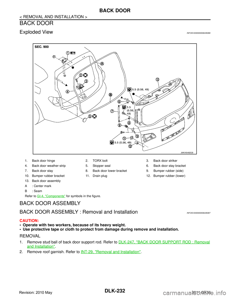
Exploded ViewINFOID:0000000006226086
BACK DOOR ASSEMBLY
BACK DOOR ASSEMBLY : Removal and InstallationINFOID:0000000006226087
CAUTION:
Operate with two workers, because of its heavy weight.
Use protective tape or cloth to protect fr om damage during remove and installation.
REMOVAL
1. Remove stud ball of back door support rod. Refer to DLK-247, "BACK DOOR SUPPORT ROD : Removal
and Installation".
2. Remove roof garnish. Refer to INT-29, "
Removal and Installation".
1. Back door hinge 2. TORX bolt 3. Back door striker
4. Back door weather-strip 5. Stopper seal 6. Back door stay bracket
7. Back door stay 8. Back door lower bracket 9. Bumper rubber (side)
10. Bumper rubber bracket 11. Drain plug 12. Bumper rubber (lower)
13. Back door assembly
A : Center mark
B: Seam
Refer to GI-4, "
Components" for symbols in the figure.
JMKIA5482GB
Revision: 2010 May2011 QX56
Page 1769 of 5598
BACK DOORDLK-233
< REMOVAL AND INSTALLATION >
C
DE
F
G H
I
J
L
M A
B
DLK
N
O P
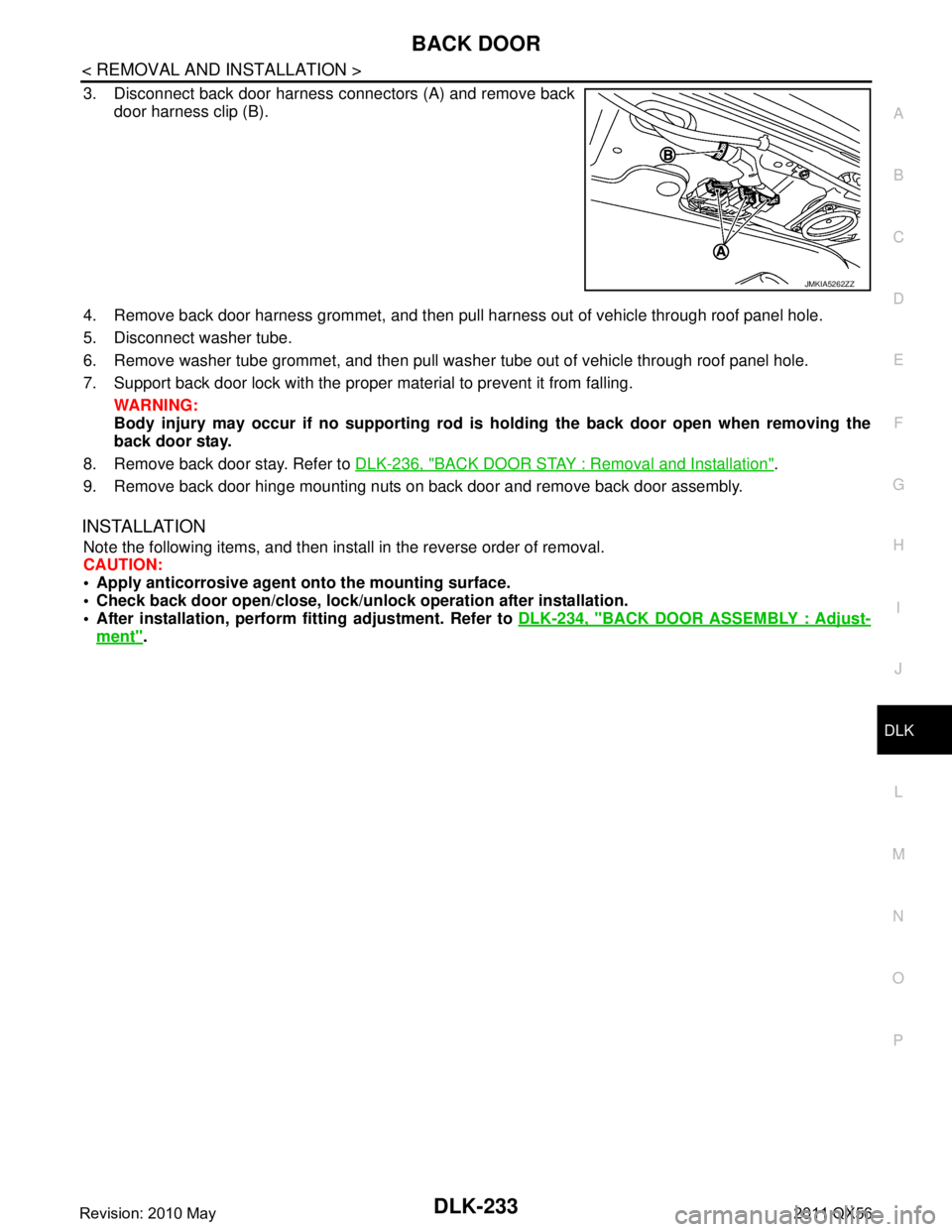
3. Disconnect back door harness connectors (A) and remove back door harness clip (B).
4. Remove back door harness grommet, and then pull harness out of vehicle through roof panel hole.
5. Disconnect washer tube.
6. Remove washer tube grommet, and then pull was her tube out of vehicle through roof panel hole.
7. Support back door lock with the proper material to prevent it from falling. WARNING:
Body injury may occur if no sup porting rod is holding the back door open when removing the
back door stay.
8. Remove back door stay. Refer to DLK-236, "
BACK DOOR STAY : Removal and Installation".
9. Remove back door hinge mounting nuts on back door and remove back door assembly.
INSTALLATION
Note the following items, and then install in the reverse order of removal.
CAUTION:
Apply anticorrosive agen t onto the mounting surface.
Check back door open/close, lock/un lock operation after installation.
After installation, perform fitting adjustment. Refer to DLK-234, "
BACK DOOR ASSEMBLY : Adjust-
ment".
JMKIA5262ZZ
Revision: 2010 May2011 QX56
Page 1770 of 5598
DLK-234
< REMOVAL AND INSTALLATION >
BACK DOOR
BACK DOOR ASSEMBLY : Adjustment
INFOID:0000000006226088
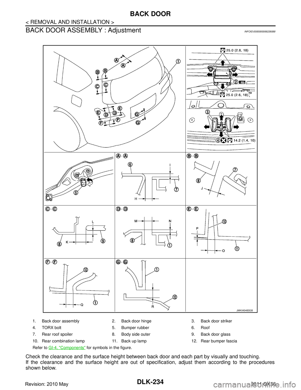
Check the clearance and the surface height between back door and each part by visually and touching.
If the clearance and the surface height are out of spec ification, adjust them according to the procedures
shown below.
1. Back door assembly 2. Back door hinge 3. Back door striker
4. TORX bolt 5. Bumper rubber 6. Roof
7. Rear roof spoiler 8. Body side outer 9. Back door glass
10. Rear combination lamp 11. Back up lamp 12. Rear bumper fascia
Refer to GI-4, "
Components" for symbols in the figure.
JMKIA5483GB
Revision: 2010 May2011 QX56
Page 1771 of 5598
BACK DOORDLK-235
< REMOVAL AND INSTALLATION >
C
DE
F
G H
I
J
L
M A
B
DLK
N
O P
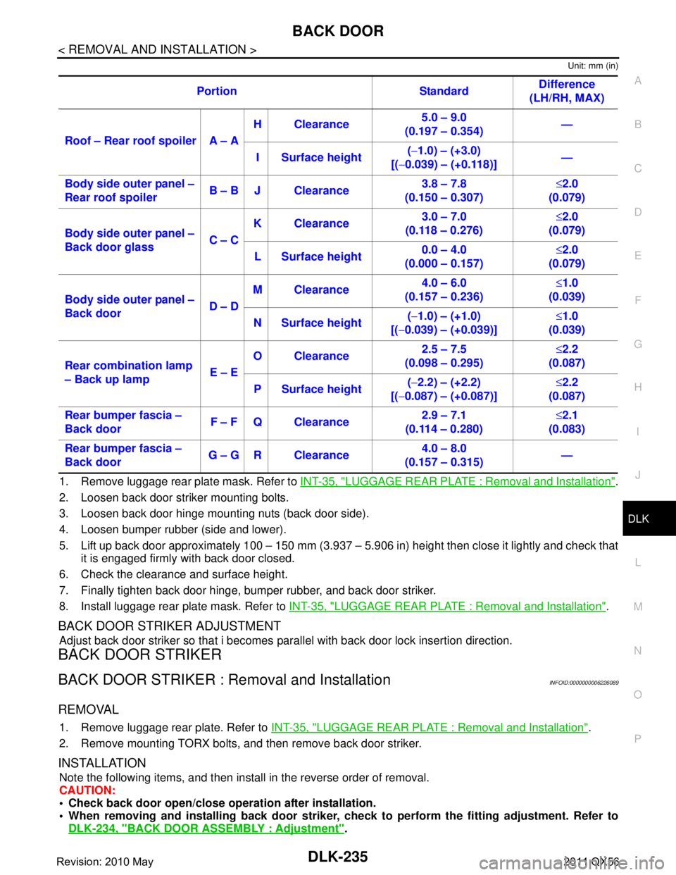
Unit: mm (in)
1. Remove luggage rear plate mask. Refer to INT-35, "LUGGAGE REAR PLATE : Removal and Installation".
2. Loosen back door striker mounting bolts.
3. Loosen back door hinge mounting nuts (back door side).
4. Loosen bumper rubber (side and lower).
5. Lift up back door approximately 100 – 150 mm (3.937 – 5.906 in) height then close it lightly and check that
it is engaged firmly with back door closed.
6. Check the clearance and surface height.
7. Finally tighten back door hinge, bumper rubber, and back door striker.
8. Install luggage rear plate mask. Refer to INT-35, "
LUGGAGE REAR PLATE : Removal and Installation".
BACK DOOR STRIKER ADJUSTMENT
Adjust back door striker so that i becomes parallel with back door lock insertion direction.
BACK DOOR STRIKER
BACK DOOR STRIKER : Removal and InstallationINFOID:0000000006226089
REMOVAL
1. Remove luggage rear plate. Refer to INT-35, "LUGGAGE REAR PLATE : Removal and Installation".
2. Remove mounting TORX bolts, and then remove back door striker.
INSTALLATION
Note the following items, and then install in the reverse order of removal.
CAUTION:
Check back door open/close ope ration after installation.
When removing and installing b ack door striker, check to perform th e fitting adjustment. Refer to
DLK-234, "
BACK DOOR ASSEMBLY : Adjustment".
Portion Standard
Difference
(LH/RH, MAX)
Roof – Rear roof spoiler A – A H Clearance
5.0 – 9.0
(0.197 – 0.354) —
I Surface height (
− 1.0) – (+3.0)
[( −0.039) – (+0.118)] —
Body side outer panel –
Rear roof spoiler B – B J Clearance 3.8 – 7.8
(0.150 – 0.307) ≤
2.0
(0.079)
Body side outer panel –
Back door glass C – CK Clearance
3.0 – 7.0
(0.118 – 0.276) ≤
2.0
(0.079)
L Surface height 0.0 – 4.0
(0.000 – 0.157) ≤
2.0
(0.079)
Body side outer panel –
Back door D – DM Clearance
4.0 – 6.0
(0.157 – 0.236) ≤
1.0
(0.039)
N Surface height (
− 1.0) – (+1.0)
[( −0.039) – (+0.039)] ≤
1.0
(0.039)
Rear combination lamp
– Back up lamp E – EO Clearance
2.5 – 7.5
(0.098 – 0.295) ≤
2.2
(0.087)
P Surface height (
− 2.2) – (+2.2)
[( −0.087) – (+0.087)] ≤
2.2
(0.087)
Rear bumper fascia –
Back door F – F Q Clearance 2.9 – 7.1
(0.114 – 0.280) ≤
2.1
(0.083)
Rear bumper fascia –
Back door G – G R Clearance 4.0 – 8.0
(0.157 – 0.315) —
Revision: 2010 May2011 QX56
Page 1809 of 5598
![INFINITI QX56 2011 Factory Service Manual
PRECAUTIONSDLN-7
< PRECAUTION > [TRANSFER: ATX90A]
C
EF
G H
I
J
K L
M A
B
DLN
N
O P
5. When the repair work is completed, re-connect both battery cables. With the brake pedal released, turn
the push INFINITI QX56 2011 Factory Service Manual
PRECAUTIONSDLN-7
< PRECAUTION > [TRANSFER: ATX90A]
C
EF
G H
I
J
K L
M A
B
DLN
N
O P
5. When the repair work is completed, re-connect both battery cables. With the brake pedal released, turn
the push](/manual-img/42/57033/w960_57033-1808.png)
PRECAUTIONSDLN-7
< PRECAUTION > [TRANSFER: ATX90A]
C
EF
G H
I
J
K L
M A
B
DLN
N
O P
5. When the repair work is completed, re-connect both battery cables. With the brake pedal released, turn
the push-button ignition switch from ACC position to ON position, then to LOCK position. (The steering
wheel will lock when the push-button ignition switch is turned to LOCK position.)
6. Perform self-diagnosis check of a ll control units using CONSULT-III.
Service Notice or Precautions for TransferINFOID:0000000006222211
CAUTION:
Use Genuine NISSAN Transfer Fluid. Refer to MA-10, "
Fluids and Lubricants".
Never reuse transfer fluid, once it has been drained.
Check the fluid level or repl ace the fluid only with the vehicle parked on level ground.
During removal or installati on, keep inside of transfer clear of dust or dirt.
Replace all tires at the same time. Always use tir es of the proper size and the same brand and pat-
tern. Fitting improper size and unusually worn tires applies excessive force to vehicle mechanism
and can cause longitudinal vibration.
Disassembly should be done in a clean work area, it is preferable to work in dustproof area.
Before proceeding with disassembly, thoroughly clean the transfer. It is important to prevent the
internal parts from becoming contamin ated by dirt or other foreign matter.
All parts should be carefully cl eaned with a general purpose, non-flammable solvent before inspec-
tion or reassembly.
Check for the correct installation status prior to removal or disassembly. If matching marks are
required, be certain they do not interfere wit h the function of the parts when applied.
Check appearance of the disassembled parts for damage, deformation, and unusual wear. Replace
them with a new ones if necessary.
Gaskets, seals and O-rings should be replaced any time the transfer is disassembled.
In principle, tighten bolts or nu ts gradually in several steps workin g diagonally from inside to out-
side. If tightening sequence is specified, use it.
Observe the specified torque when assembling.
Clean and flush the parts su fficiently and blow-dry them.
Be careful not to damage sliding surfaces and mating surfaces.
Clean inner parts with lint-free cloth or towels . Do not use cotton work gloves and rags to prevent
adhering fibers.
Revision: 2010 May2011 QX56
Page 1950 of 5598
![INFINITI QX56 2011 Factory Service Manual
DLN-148
< PRECAUTION >[FRONT FINAL DRIVE: R180A]
PRECAUTIONS
PRECAUTION
PRECAUTIONS
Precaution Necessary for Steering W
heel Rotation after Battery Disconnect
INFOID:0000000006222372
NOTE:
Before r INFINITI QX56 2011 Factory Service Manual
DLN-148
< PRECAUTION >[FRONT FINAL DRIVE: R180A]
PRECAUTIONS
PRECAUTION
PRECAUTIONS
Precaution Necessary for Steering W
heel Rotation after Battery Disconnect
INFOID:0000000006222372
NOTE:
Before r](/manual-img/42/57033/w960_57033-1949.png)
DLN-148
< PRECAUTION >[FRONT FINAL DRIVE: R180A]
PRECAUTIONS
PRECAUTION
PRECAUTIONS
Precaution Necessary for Steering W
heel Rotation after Battery Disconnect
INFOID:0000000006222372
NOTE:
Before removing and installing any control units, first tu rn the push-button ignition switch to the LOCK posi-
tion, then disconnect bot h battery cables.
After finishing work, confirm that all control unit connectors are connected properly, then re-connect both
battery cables.
Always use CONSULT-III to perform self-diagnosis as a part of each function inspection after finishing work.
If a DTC is detected, perform trouble diagnos is according to self-diagnosis results.
For vehicle with steering lock unit, if the battery is disconnected or discharged, the steering wheel will lock and
cannot be turned.
If turning the steering wheel is required with the bat tery disconnected or discharged, follow the operation pro-
cedure below before starting the repair operation.
OPERATION PROCEDURE
1. Connect both battery cables. NOTE:
Supply power using jumper cables if battery is discharged.
2. Turn the push-button ignition switch to ACC position. (At this time, the steering lock will be released.)
3. Disconnect both battery cables. The steering lock wi ll remain released with both battery cables discon-
nected and the steering wheel can be turned.
4. Perform the necessary repair operation.
5. When the repair work is completed, re-connect bot h battery cables. With the brake pedal released, turn
the push-button ignition switch from ACC position to ON position, then to LOCK position. (The steering
wheel will lock when the push-button igniti on switch is turned to LOCK position.)
6. Perform self-diagnosis check of all control units using CONSULT-III.
Precaution for Servicing Front Final DriveINFOID:0000000006222373
Before starting diagnosis of the vehicle, understand the symptoms well. Perform correct and systematic
operations.
Check for the correct installation status prior to re moval or disassembly. When matching marks are required,
be certain they do not interfere with the f unction of the parts they are applied to.
Overhaul should be done in a clean work area, a dust proof area is recommended.
Before disassembly, completely remove sand and mud from the exterior of the unit, preventing them from
entering into the unit during disassembly or assembly.
Always use shop paper for cleaning the inside of components.
Avoid using cotton gloves or a shop cloth to prevent the entering of lint.
Check appearance of the disassembled parts for dam age, deformation, and abnormal wear. Replace them
with new ones if necessary.
Gaskets, seals and O-rings should be replaced any time the unit is disassembled.
Clean and flush the parts sufficiently and blow them dry.
Be careful not to damage sliding surfaces and mating surfaces.
When applying sealant, remove the old sealant from the mating surface; then remove any moisture, oil, and
foreign materials from the application and mating surfaces.
In principle, tighten nuts or bolts gradually in severa l steps working diagonally from inside to outside. If a
tightening sequence is specified, observe it.
During assembly, observe the specified tightening torque.
Add new differential gear oil, petroleum jelly, or multi-purpose grease, as specified.
Revision: 2010 May2011 QX56