2011 INFINITI QX56 roof
[x] Cancel search: roofPage 3002 of 5598
GI-38
< BASIC INSPECTION >
SERVICE INFORMATION FOR ELECTRICAL INCIDENT
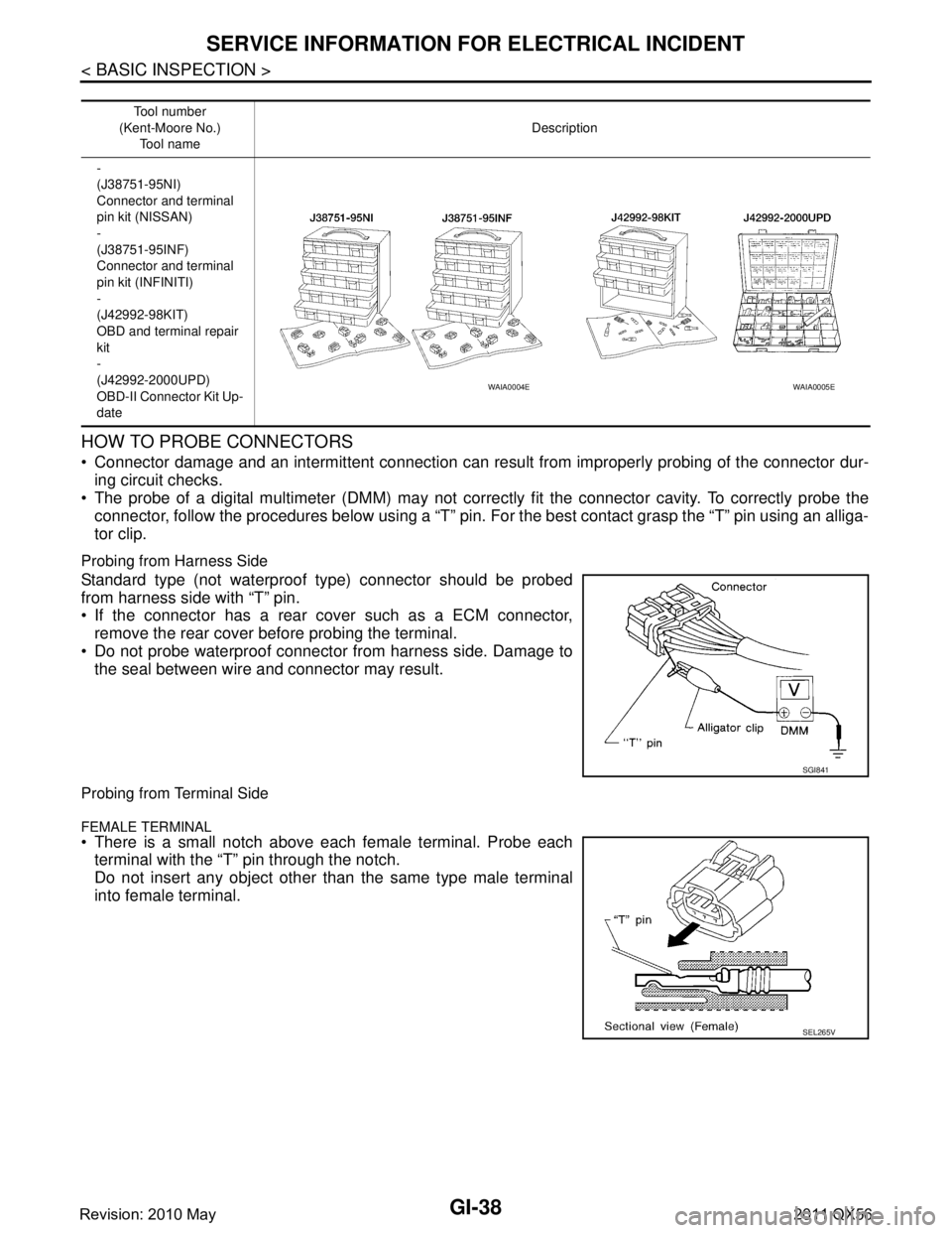
HOW TO PROBE CONNECTORS
Connector damage and an intermittent connection can result from improperly probing of the connector dur-
ing circuit checks.
The probe of a digital multimeter (DMM) may not corre ctly fit the connector cavity. To correctly probe the
connector, follow the procedures below using a “T” pin. For the best contact grasp the “T” pin using an alliga-
tor clip.
Probing from Harness Side
Standard type (not waterproof type) connector should be probed
from harness side with “T” pin.
If the connector has a rear cover such as a ECM connector,
remove the rear cover before probing the terminal.
Do not probe waterproof connector from harness side. Damage to the seal between wire and connector may result.
Probing from Terminal Side
FEMALE TERMINAL
There is a small notch above each female terminal. Probe each
terminal with the “T” pin through the notch.
Do not insert any object other than the same type male terminal
into female terminal.
Tool number
(Kent-Moore No.) Tool name Description
-
(J38751-95NI)
Connector and terminal
pin kit (NISSAN)
-
(J38751-95INF)
Connector and terminal
pin kit (INFINITI)
-
(J42992-98KIT)
OBD and terminal repair
kit
-
(J42992-2000UPD)
OBD-II Connector Kit Up-
date
WAIA0004EWAIA0005E
SGI841
SEL265V
Revision: 2010 May2011 QX56
Page 3004 of 5598
GI-40
< BASIC INSPECTION >
SERVICE INFORMATION FOR ELECTRICAL INCIDENT
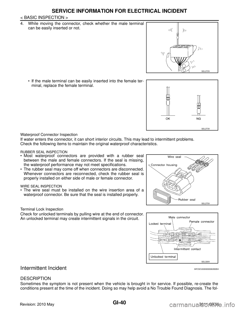
4. While moving the connector, check whether the male terminalcan be easily inserted or not.
If the male terminal can be easily inserted into the female ter-minal, replace the female terminal.
Waterproof Connector Inspection
If water enters the connector, it can short interior circuits. This may lead to intermittent problems.
Check the following items to maintain the original waterproof characteristics.
RUBBER SEAL INSPECTION Most waterproof connectors are provided with a rubber seal between the male and female connectors. If the seal is missing,
the waterproof performance may not meet specifications.
The rubber seal may come off when connectors are disconnected.
Whenever connectors are reconnected, check the rubber seal is
properly installed on either side of male or female connector.
WIRE SEAL INSPECTION The wire seal must be installed on the wire insertion area of awaterproof connector. Be sure that the seal is installed properly.
Terminal Lock Inspection
Check for unlocked terminals by pulling wire at the end of connector.
An unlocked terminal may create intermittent signals in the circuit.
Intermittent IncidentINFOID:0000000006280854
DESCRIPTION
Sometimes the symptom is not present when the vehicle is brought in for service. If possible, re-create the
conditions present at the time of the incident. Doing so may help avoid a No Trouble Found Diagnosis. The fol-
SEL272V
SEL273V
SEL275V
SEL330V
Revision: 2010 May2011 QX56
Page 3029 of 5598
INSPECTION AND ADJUSTMENTGI-65
< BASIC INSPECTION >
C
DE
F
G H
I
J
K L
M B
GI
N
O PINSPECTION AND ADJUSTMENT
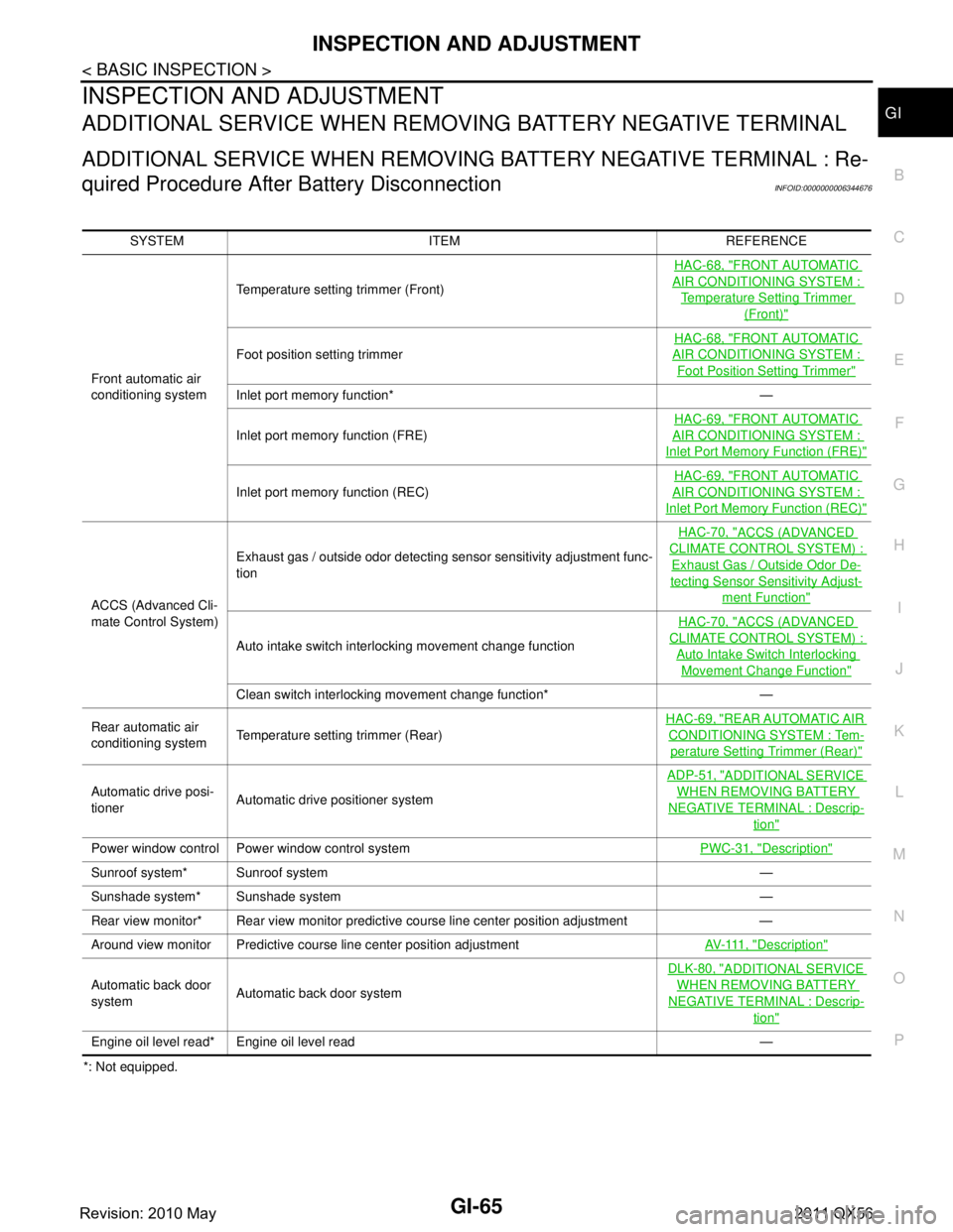
ADDITIONAL SERVICE WHEN REMOVING BATTERY NEGATIVE TERMINAL
ADDITIONAL SERVICE WHEN REMOVING BATTERY NEGATIVE TERMINAL : Re-
quired Procedure After Battery Disconnection
INFOID:0000000006344676
*: Not equipped. SYSTEM ITEM REFERENCE
Front automatic air
conditioning system Temperature setting trimmer (Front)
HAC-68, "
FRONT AUTOMATIC
AIR CONDITIONING SYSTEM :
Temperature Setting Trimmer
(Front)"
Foot position setting trimmer
HAC-68, "
FRONT AUTOMATIC
AIR CONDITIONING SYSTEM :
Foot Position Setting Trimmer"
Inlet port memory function* —
Inlet port memory function (FRE)
HAC-69, "
FRONT AUTOMATIC
AIR CONDITIONING SYSTEM :
Inlet Port Memory
Function (FRE)"
Inlet port memory function (REC) HAC-69, "
FRONT AUTOMATIC
AIR CONDITIONING SYSTEM :
Inlet Port Memory Function (REC)"
ACCS (Advanced Cli-
mate Control System)Exhaust gas / outside odor detecting sensor sensitivity adjustment func-
tion
HAC-70, "
ACCS (ADVANCED
CLIMATE CONTROL SYSTEM) :
Exhaust Gas / Outside Odor De-
tecting Sensor Sensitivity Adjust-
ment Function"
Auto intake switch interlocking movement change function
HAC-70, "
ACCS (ADVANCED
CLIMATE CONTROL SYSTEM) :
Auto Intake Switch Interlocking
Movement Change Function"
Clean switch interlocking movement change function* —
Rear automatic air
conditioning system Temperature setting trimmer (Rear) HAC-69, "
REAR AUTOMATIC AIR
CONDITIONING SYSTEM : Tem-
perature Setting
Trimmer (Rear)"
Automatic drive posi-
tioner Automatic drive positioner system ADP-51, "
ADDITIONAL SERVICE
WHEN REMOVING BATTERY
NEGATIVE TERMINAL : Descrip-
tion"
Power window control Power window control system
PWC-31, "Description"
Sunroof system* Sunroof system —
Sunshade system* Sunshade system —
Rear view monitor* Rear view monitor predictive course line center position adjustment —
Around view monitor Predictive course line center position adjustment AV- 111 , "
Description"
Automatic back door
systemAutomatic back door system DLK-80, "
ADDITIONAL SERVICE
WHEN REMOVING BATTERY
NEGATIVE TERMINAL : Descrip-
tion"
Engine oil level read* Engine oil level read —
Revision: 2010 May2011 QX56
Page 3030 of 5598

GW-1
BODY EXTERIOR, DOORS, ROOF & VEHICLE SECURITY
C
D
E
F
G H
I
J
L
M
SECTION GW
A
B
GW
N
O P
CONTENTS
GLASS & WINDOW SYSTEM
PRECAUTION ................ ...............................2
PRECAUTIONS .............................................. .....2
Precaution for Supplemental Restraint System
(SRS) "AIR BAG" and "SEAT BELT PRE-TEN-
SIONER" ............................................................. ......
2
Precaution Necessary for Steering Wheel Rota-
tion after Battery Disconnect .....................................
2
Precaution for Procedure without Cowl Top Cover ......3
Handling for Adhesive and Primer ............................3
PREPARATION ............................................4
PREPARATION .............................................. .....4
Special Service Tools ........................................ ......4
Commercial Service Tools .......................................4
SYMPTOM DIAGNOSIS ...............................5
SQUEAK AND RATTLE TROUBLE DIAG-
NOSES ........................ ........................................
5
Work Flow ........................................................... ......5
Inspection Procedure ................................................7
Diagnostic Worksheet ...............................................9
REMOVAL AND INSTALLATION ...............11
WINDSHIELD GLASS .................................... ....11
Exploded View .................................................... ....11
Removal and Installation .........................................12
Inspection ................................................................13
SIDE WINDOW GLASS ....................................14
Exploded View ..................................................... ....14
Removal and Installation .........................................15
Inspection ................................................................15
BACK DOOR WINDOW GLASS ......................16
Exploded View ..................................................... ....16
Removal and Installation .........................................16
Inspection ................................................................17
FRONT DOOR GLASS .....................................19
Exploded View .........................................................19
Removal and Installation .........................................19
Inspection and Adjustment ......................................20
FRONT REGULATOR .......................................21
Exploded View .........................................................21
Removal and Installation .........................................21
Disassembly and Assembly .....................................21
Inspection and Adjustment ......................................22
REAR DOOR GLASS .......................................23
Exploded View .........................................................23
Removal and Installation .........................................23
Inspection and Adjustment ......................................25
REAR REGULATOR .........................................26
Exploded View .........................................................26
Removal and Installation .........................................26
Disassembly and Assembly .....................................27
Inspection and Adjustment ......................................27
Revision: 2010 May2011 QX56
Page 3037 of 5598

GW-8
< SYMPTOM DIAGNOSIS >
SQUEAK AND RATTLE TROUBLE DIAGNOSES
3. The trunk lid torsion bars knocking together
4. A loose license plate or bracket
Most of these incidents can be repaired by adjusting, securing or insulatingthe item(s) or component(s) caus-
ing the noise.
SUNROOF/HEADLINING
Noises in the sunroof/headlining area c an often be traced to one of the following:
1. Sunroof lid, rail, linkage or seals making a rattle or light knockingnoise
2. Sunvisor shaft shaking in the holder
3. Front or rear windshield touching headlining and squeaking
Again, pressing on the components to stop the noise while duplicatingthe conditions can isolate most of these
incidents. Repairs usually consistof insulating with felt cloth tape.
SEATS
When isolating seat noise it's important to note the pos ition the seatis in and the load placed on the seat when
the noise is present. These conditionsshould be duplic ated when verifying and isolating the cause of the
noise.
Cause of seat noise include:
1. Headrest rods and holder
2. A squeak between the seat pad cushion and frame
3. The rear seatback lock and bracket
These noises can be isolated by moving or pressing on the suspectedcomponents while duplicating the condi-
tions under which the noise occurs. Most of these incidents can be repaired by repositioning the component
orapplying urethane tape to the contact area.
UNDERHOOD
Some interior noise may be caused by components under the hood or onthe engine wall. The noise is then
transmitted into the passenger compartment.
Causes of transmitted underhood noise include:
1. Any component mounted to the engine wall
2. Components that pass through the engine wall
3. Engine wall mounts and connectors
4. Loose radiator mounting pins
5. Hood bumpers out of adjustment
6. Hood striker out of adjustment
These noises can be difficult to isolate since they cannot be reached from the interior of the vehicle. The best
method is to secure, move or insulate one component at a time and test drive the \
vehicle. Also, engine RPM
or load can be changed to isolate the noise. Repairs can usually be made by moving, adjusting, securing, or
insulating the component causing the noise.
Revision: 2010 May2011 QX56
Page 3040 of 5598
WINDSHIELD GLASSGW-11
< REMOVAL AND INSTALLATION >
C
DE
F
G H
I
J
L
M A
B
GW
N
O P
REMOVAL AND INSTALLATION
WINDSHIELD GLASS
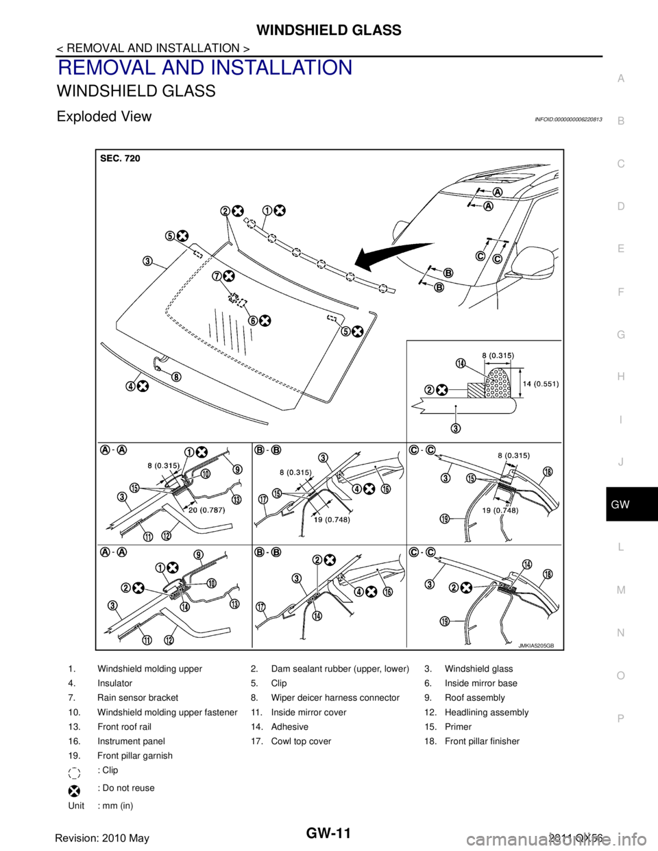
Exploded ViewINFOID:0000000006220813
1. Windshield molding upper 2. Dam sealant rubber (upper, lower) 3. Windshield glass
4. Insulator 5. Clip 6. Inside mirror base
7. Rain sensor bracket 8. Wiper deicer harness connector 9. Roof assembly
10. Windshield molding upper fastener 11. Inside mirror cover 12. Headlining assembly
13. Front roof rail 14. Adhesive 15. Primer
16. Instrument panel 17. Cowl top cover 18. Front pillar finisher
19. Front pillar garnish : Clip
: Do not reuse
Unit : mm (in)
JMKIA5205GB
Revision: 2010 May2011 QX56
Page 3102 of 5598
HA-46
< REMOVAL AND INSTALLATION >
REAR A/C UNIT
REAR A/C UNIT
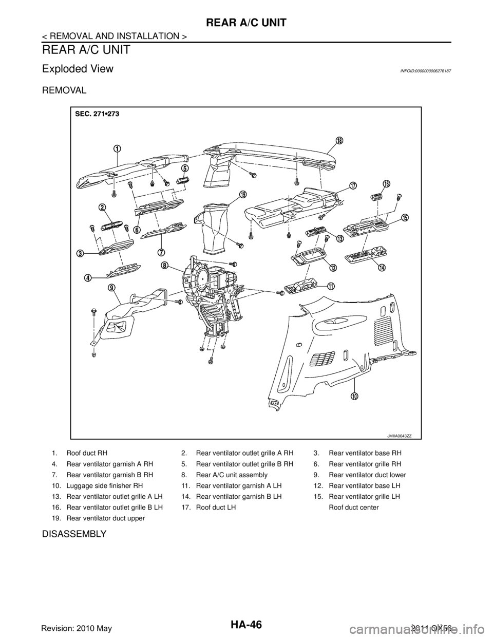
Exploded ViewINFOID:0000000006276187
REMOVAL
DISASSEMBLY
1. Roof duct RH 2. Rear ventilator outlet grille A RH 3. Rear ventilator base RH
4. Rear ventilator garnish A RH 5. Rear ventilator outlet grille B RH 6. Rear ventilator grille RH
7. Rear ventilator garnish B RH 8. Rear A/C unit assembly 9. Rear ventilator duct lower
10. Luggage side finisher RH 11. Rear ventilator garnish A LH 12. Rear ventilator base LH
13. Rear ventilator outlet grille A LH 14. Rear ventilator garnish B LH 15. Rear ventilator grille LH
16. Rear ventilator outlet grille B LH 17. Roof duct LH Roof duct center
19. Rear ventilator duct upper
JMIIA0643ZZ
Revision: 2010 May2011 QX56
Page 3348 of 5598
LUGGAGE ROOM LAMPINL-81
< REMOVAL AND INSTALLATION >
C
DE
F
G H
I
J
K
M A
B
INL
N
O P
LUGGAGE ROOM LAMP
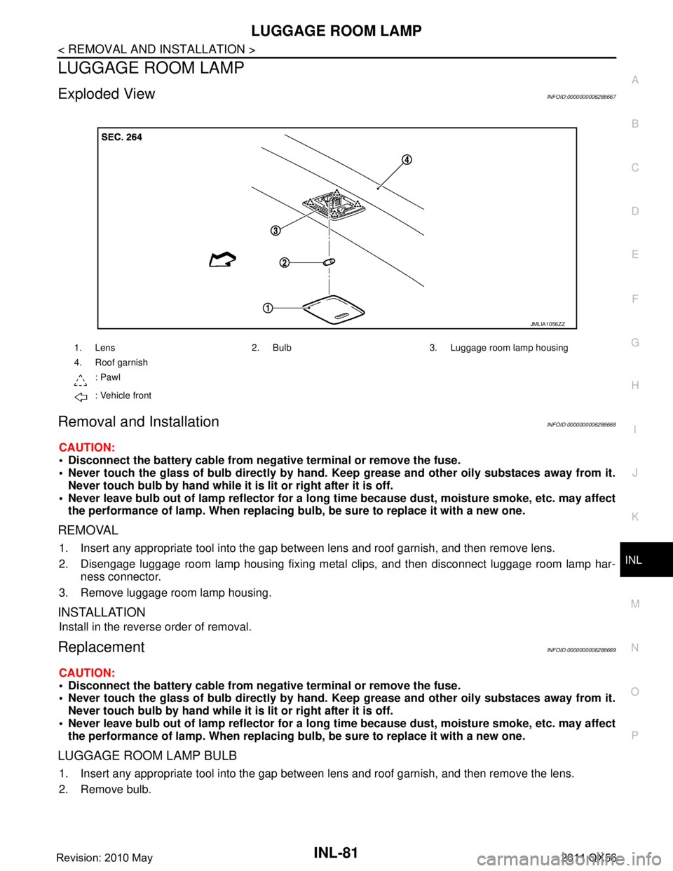
Exploded ViewINFOID:0000000006288667
Removal and InstallationINFOID:0000000006288668
CAUTION:
Disconnect the battery cable from negative terminal or remove the fuse.
Never touch the glass of bulb directly by hand. Keep grease and other oily substaces away from it.
Never touch bulb by hand while it is lit or right after it is off.
Never leave bulb out of lamp reflector for a long time because dust, moisture smoke, etc. may affect
the performance of lamp. When replacing bu lb, be sure to replace it with a new one.
REMOVAL
1. Insert any appropriate tool into the gap betw een lens and roof garnish, and then remove lens.
2. Disengage luggage room lamp housing fixing metal clips, and then disconnect luggage room lamp har- ness connector.
3. Remove luggage room lamp housing.
INSTALLATION
Install in the reverse order of removal.
ReplacementINFOID:0000000006288669
CAUTION:
Disconnect the battery cable from negative terminal or remove the fuse.
Never touch the glass of bulb directly by hand. Keep grease and other oily substaces away from it.
Never touch bulb by hand while it is lit or right after it is off.
Never leave bulb out of lamp reflector for a long time because dust, moisture smoke, etc. may affect
the performance of lamp. When replacing bu lb, be sure to replace it with a new one.
LUGGAGE ROOM LAMP BULB
1. Insert any appropriate tool into the gap between lens and roof garnish, and then remove the lens.
2. Remove bulb.
1. Lens 2. Bulb 3. Luggage room lamp housing
4. Roof garnish
: Pawl
: Vehicle front
JMLIA1056ZZ
Revision: 2010 May2011 QX56