2011 INFINITI QX56 roof
[x] Cancel search: roofPage 1988 of 5598
![INFINITI QX56 2011 Factory Service Manual
DLN-186
< PRECAUTION >[REAR FINAL DRIVE: R230]
PRECAUTIONS
PRECAUTION
PRECAUTIONS
Service Notice or Precautions for Rear Final DriveINFOID:0000000006222406
Check for the correct installation status INFINITI QX56 2011 Factory Service Manual
DLN-186
< PRECAUTION >[REAR FINAL DRIVE: R230]
PRECAUTIONS
PRECAUTION
PRECAUTIONS
Service Notice or Precautions for Rear Final DriveINFOID:0000000006222406
Check for the correct installation status](/manual-img/42/57033/w960_57033-1987.png)
DLN-186
< PRECAUTION >[REAR FINAL DRIVE: R230]
PRECAUTIONS
PRECAUTION
PRECAUTIONS
Service Notice or Precautions for Rear Final DriveINFOID:0000000006222406
Check for the correct installation status prior to removal or disassembly. If matching marks are required, be
certain they never interfere with the function of the parts when applied.
Overhaul should be done in a clean work area, it is preferable to work in dustproof area.
Before disassembly, using steam or white gasoline, completely remove sand and mud from the exterior of
the unit, preventing them from entering into the unit during disassembly or assembly.
Check appearance of the disassembled parts for dam age, deformation, and unusual wear. Replace them
with new ones, if necessary.
Gaskets, seals and O-rings should be replaced any time when the unit is disassembled.
In principle, tighten bolts or nuts gradually in several steps working diagonally from inside to outside. If tight-
ening sequence is specified, observe it.
Clean and flush the parts sufficiently and blow-dry them.
Be careful not to damage sliding surfaces and mating surfaces.
When applying sealant, remove the old sealant from t he mounting surface; then remove any moisture, oil,
and foreign materials from the application and mounting surfaces.
Always use shop paper for cleaning the inside of components.
Never use cotton gloves or shop rags to prevent entering of lint.
During assembly, observe the specified tightening tor que, and apply new gear oil, petroleum jelly, or multi-
purpose grease as specified for each vehicle, if necessary.
Revision: 2010 May2011 QX56
Page 2856 of 5598
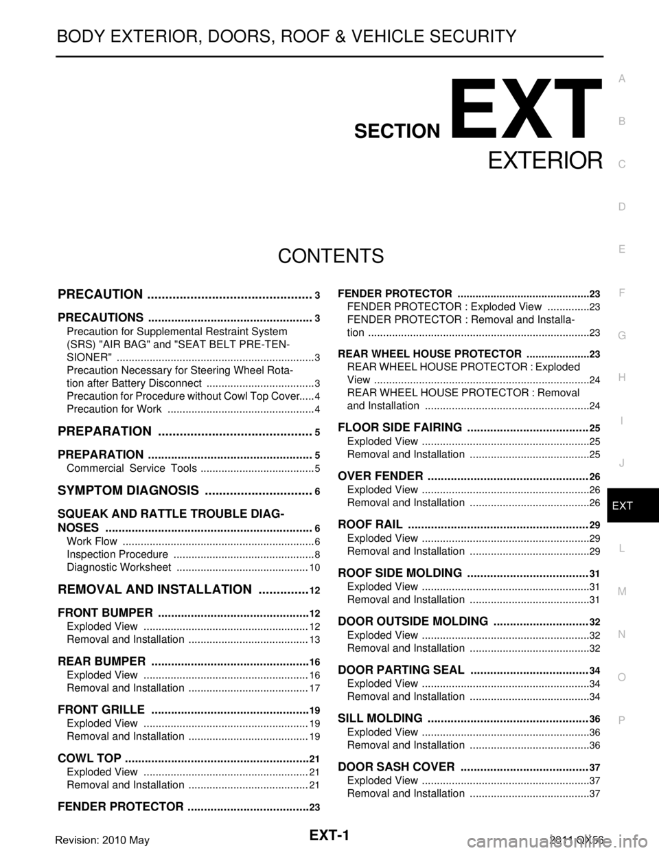
EXT-1
BODY EXTERIOR, DOORS, ROOF & VEHICLE SECURITY
C
D
E
F
G H
I
J
L
M
SECTION EXT
A
B
EXT
N
O P
CONTENTS
EXTERIOR
PRECAUTION ................ ...............................3
PRECAUTIONS .............................................. .....3
Precaution for Supplemental Restraint System
(SRS) "AIR BAG" and "SEAT BELT PRE-TEN-
SIONER" ............................................................. ......
3
Precaution Necessary for Steering Wheel Rota-
tion after Battery Disconnect .....................................
3
Precaution for Procedure without Cowl Top Cover ......4
Precaution for Work ..................................................4
PREPARATION ............................................5
PREPARATION .............................................. .....5
Commercial Service Tools ................................. ......5
SYMPTOM DIAGNOSIS ...............................6
SQUEAK AND RATTLE TROUBLE DIAG-
NOSES ........................ ........................................
6
Work Flow ........................................................... ......6
Inspection Procedure ................................................8
Diagnostic Worksheet .............................................10
REMOVAL AND INSTALLATION ...............12
FRONT BUMPER ........................................... ....12
Exploded View .................................................... ....12
Removal and Installation .........................................13
REAR BUMPER .................................................16
Exploded View .................................................... ....16
Removal and Installation .........................................17
FRONT GRILLE .................................................19
Exploded View .................................................... ....19
Removal and Installation .........................................19
COWL TOP .........................................................21
Exploded View .................................................... ....21
Removal and Installation .........................................21
FENDER PROTECTOR ......................................23
FENDER PROTECTOR ......................................... ....23
FENDER PROTECTOR : Exploded View ...............23
FENDER PROTECTOR : Removal and Installa-
tion ...........................................................................
23
REAR WHEEL HOUSE PROTECTOR .................. ....23
REAR WHEEL HOUSE PROTECTOR : Exploded
View .........................................................................
24
REAR WHEEL HOUSE PROTECTOR : Removal
and Installation ........................................................
24
FLOOR SIDE FAIRING .....................................25
Exploded View .........................................................25
Removal and Installation .........................................25
OVER FENDER .................................................26
Exploded View .........................................................26
Removal and Installation .........................................26
ROOF RAIL .......................................................29
Exploded View .........................................................29
Removal and Installation .........................................29
ROOF SIDE MOLDING .....................................31
Exploded View .........................................................31
Removal and Installation .........................................31
DOOR OUTSIDE MOLDING .............................32
Exploded View .........................................................32
Removal and Installation .........................................32
DOOR PARTING SEAL ....................................34
Exploded View .........................................................34
Removal and Installation .........................................34
SILL MOLDING .................................................36
Exploded View .........................................................36
Removal and Installation .........................................36
DOOR SASH COVER .......................................37
Exploded View .........................................................37
Removal and Installation .........................................37
Revision: 2010 May2011 QX56
Page 2864 of 5598
SQUEAK AND RATTLE TROUBLE DIAGNOSESEXT-9
< SYMPTOM DIAGNOSIS >
C
DE
F
G H
I
J
L
M A
B
EXT
N
O P
1. Trunk lid dumpers out of adjustment
2. Trunk lid striker out of adjustment
3. Trunk lid torsion bars knocking together
4. A loose license plate or bracket
Most of these incidents can be repaired by adjusting, se curing, or insulating the item(s) or component(s) caus-
ing the noise.
SUNROOF/HEADLINING
Noises in the sunroof / headlining area can of ten be traced to one of the following items:
1. Sunroof lid, rail, linkage, or seals making a rattle or light knocking noise
2. Sunvisor shaft shaking in the holder
3. Front or rear windshield touching headlining and squeaking
Again, pressing on the components to stop the noise while duplicating the conditions can isolate most of these
incidents. Repairs usually consist of insulating with felt cloth tape.
SEATS
When isolating seat noise it is important to note the position the seat is in and the load placed on the seat
when the noise occurs. These conditions should be duplic ated when verifying and isolating the cause of the
noise.
Causes of seat noise include:
1. Headrest rods and holder
2. A squeak between the seat pad cushion and frame
3. The rear seatback lock and bracket
These noises can be isolated by moving or pressing on the suspected components while duplicating the con-
ditions under which the noise occurs. Most of thes e incidents can be repaired by repositioning the component
or applying urethane tape to the contact area.
UNDERHOOD
Some interior noise may be caused by components under the hood or on the engine wall. The noise is then
transmitted into the passenger compartment.
Causes of transmitted underhood noise include:
1. Any component mounted to the engine wall
2. Components that pass through the engine wall
3. Engine wall mounts and connectors
4. Loose radiator mounting pins
5. Hood bumpers out of adjustment
6. Hood striker out of adjustment
These noises can be difficult to isolate since they cannot be reached from the interior of the vehicle. The best
method is to secure, move, or insulate one component at a time and test drive the vehicle. Also, engine RPM
or load can be changed to isolate the noise. Repairs c an usually be made by moving, adjusting, securing, or
insulating the component causing the noise.
Revision: 2010 May2011 QX56
Page 2884 of 5598
ROOF RAILEXT-29
< REMOVAL AND INSTALLATION >
C
DE
F
G H
I
J
L
M A
B
EXT
N
O P
ROOF RAIL
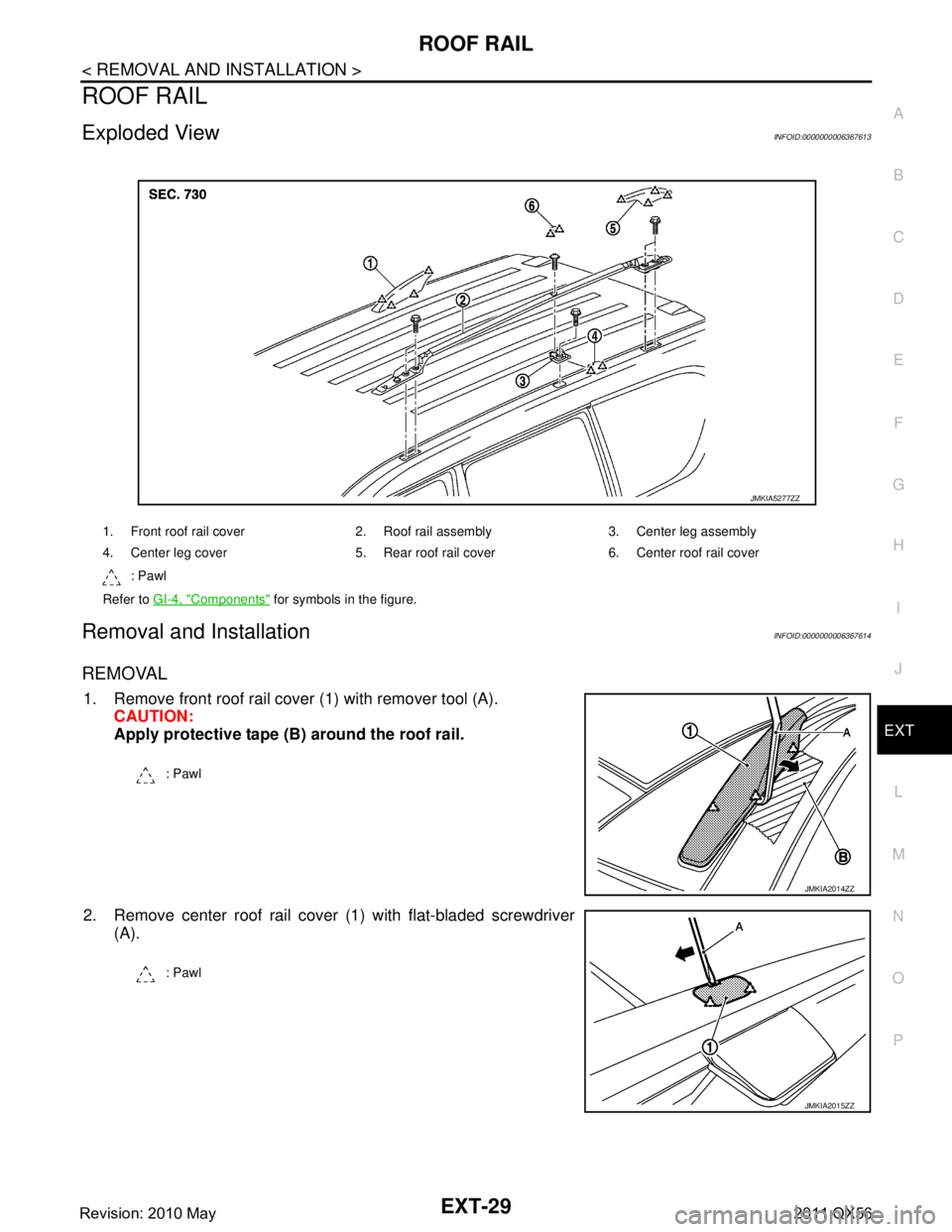
Exploded ViewINFOID:0000000006367613
Removal and InstallationINFOID:0000000006367614
REMOVAL
1. Remove front roof rail cover (1) with remover tool (A). CAUTION:
Apply protective tape (B) around the roof rail.
2. Remove center roof rail cover (1) with flat-bladed screwdriver (A).
1. Front roof rail cover 2. Roof rail assembly 3. Center leg assembly
4. Center leg cover 5. Rear roof ra il cover 6. Center roof rail cover
: Pawl
Refer to GI-4, "
Components" for symbols in the figure.
JMKIA5277ZZ
: Pawl
JMKIA2014ZZ
: Pawl
JMKIA2015ZZ
Revision: 2010 May2011 QX56
Page 2885 of 5598
EXT-30
< REMOVAL AND INSTALLATION >
ROOF RAIL
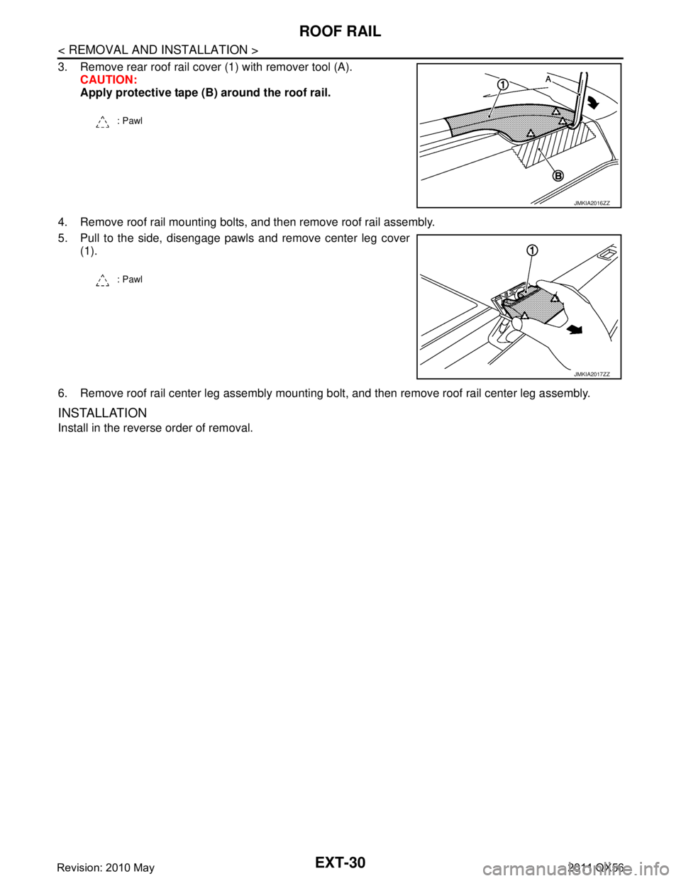
3. Remove rear roof rail cover (1) with remover tool (A).CAUTION:
Apply protective tape (B) around the roof rail.
4. Remove roof rail mounting bolts, and then remove roof rail assembly.
5. Pull to the side, disengage pawls and remove center leg cover (1).
6. Remove roof rail center leg assembly mounting bolt, and then remove roof rail center leg assembly.
INSTALLATION
Install in the reverse order of removal.
: Pawl
JMKIA2016ZZ
: Pawl
JMKIA2017ZZ
Revision: 2010 May2011 QX56
Page 2886 of 5598
ROOF SIDE MOLDINGEXT-31
< REMOVAL AND INSTALLATION >
C
DE
F
G H
I
J
L
M A
B
EXT
N
O P
ROOF SIDE MOLDING
Exploded ViewINFOID:0000000006367615
Removal and InstallationINFOID:0000000006367616
REMOVAL
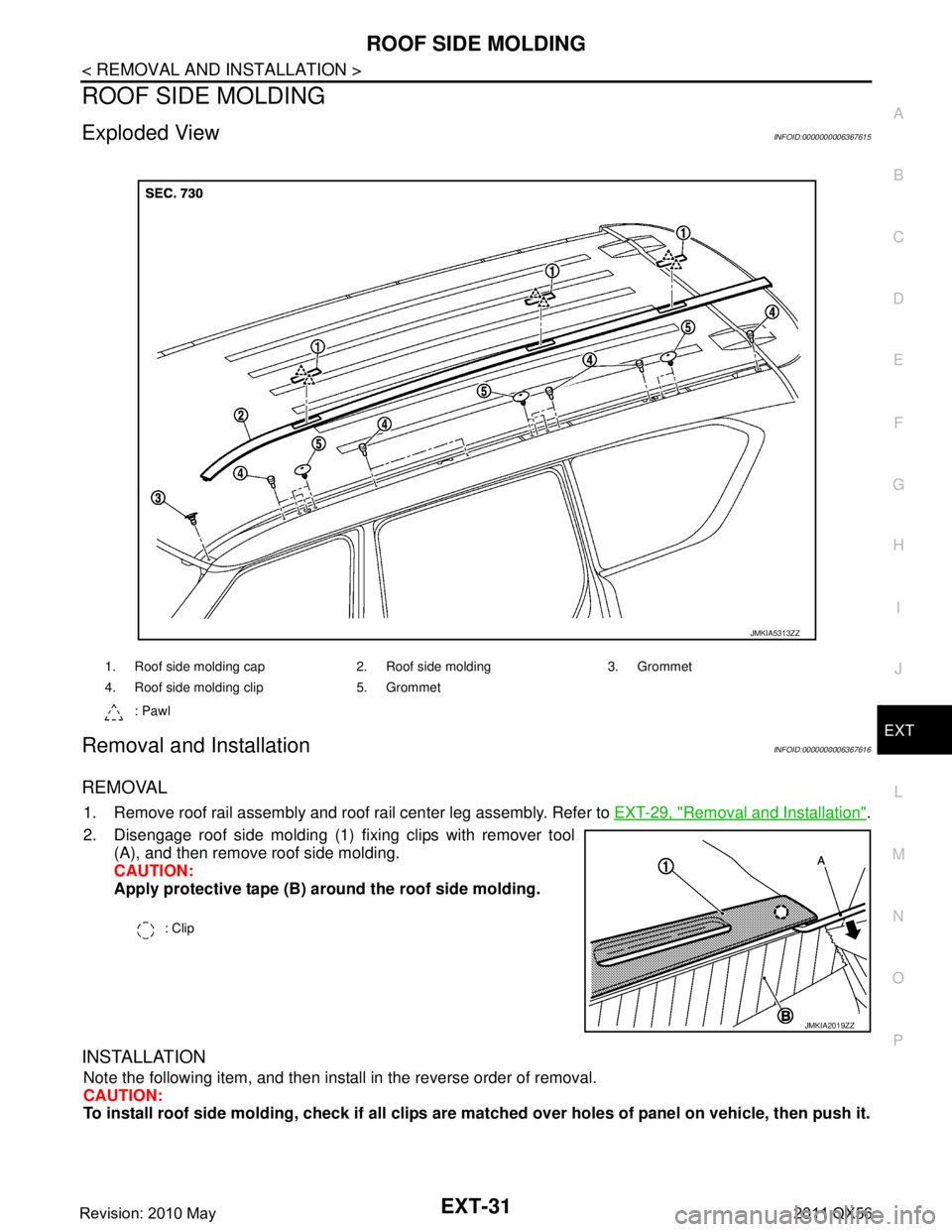
1. Remove roof rail assembly and roof rail center leg assembly. Refer to EXT-29, "Removal and Installation".
2. Disengage roof side molding (1) fixing clips with remover tool (A), and then remove roof side molding.
CAUTION:
Apply protective tape (B) ar ound the roof side molding.
INSTALLATION
Note the following item, and then install in the reverse order of removal.
CAUTION:
To install roof side molding, check if all clips are matched over ho les of panel on vehicle, then push it.
1. Roof side molding cap 2. Roof side molding 3. Grommet
4. Roof side molding clip 5. Grommet
: Pawl
JMKIA5313ZZ
: Clip
JMKIA2019ZZ
Revision: 2010 May2011 QX56
Page 2895 of 5598

EXT-40
< REMOVAL AND INSTALLATION >
FRONT PILLAR FINISHER
FRONT PILLAR FINISHER
Exploded ViewINFOID:0000000006367625
Removal and InstallationINFOID:0000000006367626
REMOVAL
1. Remove roof drip molding. Refer to EXT-43, "Removal and Installation".
2. Remove front pillar finisher fixing screw.
3. Disengage clips with remover tool, and then remove front pillar finisher.
INSTALLATION
Note the following items, and then install in the reverse order of removal.
CAUTION:
Visually check the clips for deformation and dama ge during installation. Replace with new ones if
necessary.
When installing front pillar finisher, check that cl ips are securely fitted in body panel holes, and
press them it.
1. Front pillar finisher 2. Grommet 3. Grommet
4. EPT sealer [t: 12.0 mm (0.472 in)]
: Vehicle front
Refer to GI-4, "
Components" for symbols in the figure.
JMKIA5311ZZ
Revision: 2010 May2011 QX56
Page 2931 of 5598
FL-2
< PRECAUTION >
PRECAUTIONS
PRECAUTION
PRECAUTIONS
General PrecautionsINFOID:0000000006289679
WARNING:
When replacing fuel line parts, be sure to observe the following.
• Put a “CAUTION: FLAMMABLE” sign in the workshop.
Be sure to work in a well ventilate d area and furnish workshop with a CO
2 fire extinguisher.
Never smoke while servicing fuel system. Keep open flames and sparks away from the work area.
CAUTION:
Use gasoline required by the regulations for octane number. Refer to GI-31, "
Fuel".
Before removing fuel line parts, perform out the following procedures:
- Put drained fuel in an explosi on-proof container and put the lid on securely. Keep the container in
safe area.
- Release fuel pressure from the fuel lines. Refer to EC-153, "
Work Procedure".
- Disconnect the battery cable from the negative terminal.
Always replace O-rings with new ones.
Never kink or twist tubes when they are being installed.
Never tighten hose clamps excessi vely to avoid damaging hoses.
After installing tubes, check there is no fuel leakage at connections in the following steps.
- Apply fuel pressure to fuel lin es with turning ignition switch “O N” (with engine stopped). Then check
for fuel leakage at connections.
- Start engine and rev it up and check for fuel leakage at connections.
Use only a genuine NISSAN fuel filler cap as a replacemen t. If an incorrect fuel filler cap is used, the
“MIL” may come on.
For servicing “Evaporative Emission System” parts.
Refer to EC-16, "
Component Parts Location".
Revision: 2010 May2011 QX56