2011 INFINITI QX56 roof
[x] Cancel search: roofPage 4608 of 5598

SEC-1
BODY EXTERIOR, DOORS, ROOF & VEHICLE SECURITY
C
D
E
F
G H
I
J
L
M
SECTION SEC
A
B
SEC
N
O P
CONTENTS
SECURITY CONTROL SYSTEM
WITH INTELLIGE NT KEY SYSTEM
PRECAUTION ................ ...............................
5
PRECAUTIONS .............................................. .....5
Precaution for Supplemental Restraint System
(SRS) "AIR BAG" and "SEAT BELT PRE-TEN-
SIONER" ............................................................. ......
5
Precaution Necessary for Steering Wheel Rota-
tion after Battery Disconnect .....................................
5
Precaution for Procedure without Cowl Top Cover ......6
SYSTEM DESCRIPTION ..............................7
COMPONENT PARTS ................................... .....7
Component Parts Location .................................. ......7
Component Description .............................................8
A/T Shift Selector (Detention Switch) ........................8
BCM ..........................................................................8
ECM ..........................................................................9
IPDM E/R ..................................................................9
NATS Antenna Amp. .................................................9
TCM ..........................................................................9
Combination Meter ....................................................9
Door Switch ...............................................................9
Hood Switch ..............................................................9
Inside Key Antenna ...................................................9
Intelligent Key ............................................................9
Push-button Ignition Switch .....................................10
Remote Keyless Entry Receiver .............................10
Security Indicator Lamp ..........................................10
Starter Control Relay ...............................................10
Starter Relay ...........................................................10
Steering Lock Relay ................................................10
Steering Lock Unit ...................................................10
Stop Lamp Switch ...................................................10
Transmission Range Switch ....................................10
Vehicle Information Display .....................................11
SYSTEM .............................................................12
INTELLIGENT KEY SYSTEM/ENGINE START
FUNCTION ............................................................. ....
12
INTELLIGENT KEY SYSTEM/ENGINE START
FUNCTION : System Diagram ................................
12
INTELLIGENT KEY SYSTEM/ENGINE START
FUNCTION : System Description ............................
12
INFINITI VEHICLE IMMOBILIZER SYSTEM-NATS ....14
INFINITI VEHICLE IMMOBILIZER SYSTEM-
NATS : System Diagram .........................................
15
INFINITI VEHICLE IMMOBILIZER SYSTEM-
NATS : System Description .....................................
15
VEHICLE SECURITY SYSTEM .................................17
VEHICLE SECURITY SYSTEM : System Dia-
gram .................................................................... ....
17
VEHICLE SECURITY SYSTEM : System Descrip-
tion ...........................................................................
18
DIAGNOSIS SYSTEM (BCM) ...........................21
COMMON ITEM ..................................................... ....21
COMMON ITEM : CONSULT-III Function (BCM -
COMMON ITEM) .....................................................
21
INTELLIGENT KEY ................................................ ....22
INTELLIGENT KEY : CONSULT-III Function
(BCM - INTELLIGENT KEY) ....................................
22
THEFT ALM ........................................................... ....26
THEFT ALM : CONSULT-III Function (BCM -
THEFT) ................................................................ ....
26
IMMU ...................................................................... ....27
IMMU : CONSULT-III Function (BCM - IMMU) ........27
DIAGNOSIS SYSTEM (IPDM E/R) ...................28
CONSULT-III Function (IPDM E/R) .........................28
ECU DIAGNOSIS INFORMATION ..............30
ECM, IPDM E/R, BCM .......................................30
List of ECU Reference ......................................... ....30
Revision: 2010 May2011 QX56
Page 5388 of 5598

VTL-2
REAR VENTILATOR DUCT LOWER : Removal
and Installation .......................................................
12
REAR VENTILATOR DUCT UPPER ........................12
REAR VENTILATOR DUCT UPPER : Removal
and Installation .................................................... ...
12
ROOF DUCT .......................................................... ...13
ROOF DUCT : Removal and Installation ................13
REAR VENTILATOR GRILLE ............................... ...13
REAR VENTILATOR GRILLE : Removal and In-
stallation .................................................................
13
BLOWER UNIT ..................................................14
Exploded View ..................................................... ...14
Removal and Installation ........................................15
BLOWER MOTOR .............................................16
FRONT A/C UNIT ................................................... ...16
FRONT A/C UNIT : Exploded View ........................16
FRONT A/C UNIT : Removal and Installation .........16
REAR A/C UNIT ASSEMBLY ...................................16
REAR A/C UNIT ASSEMBLY : Exploded View ... ...16
REAR A/C UNIT ASSEMBLY : Removal and In-
stallation ..................................................................
16
IN-CABIN MICROFILTER .................................17
Exploded View ..................................................... ...17
Removal and Installation .........................................17
Replacement ...........................................................17
SERVICE DATA AND SPECIFICATIONS
(SDS) .......... ................................................
18
SERVICE DATA AND SPECIFICATIONS
(SDS) .............................................................. ...
18
In-cabin microfilter ................................................ ...18
Revision: 2010 May2011 QX56
Page 5395 of 5598

DUCT AND GRILLEVTL-9
< REMOVAL AND INSTALLATION >
C
DE
F
G H
J
K L
M A
B
VTL
N
O P
REAR
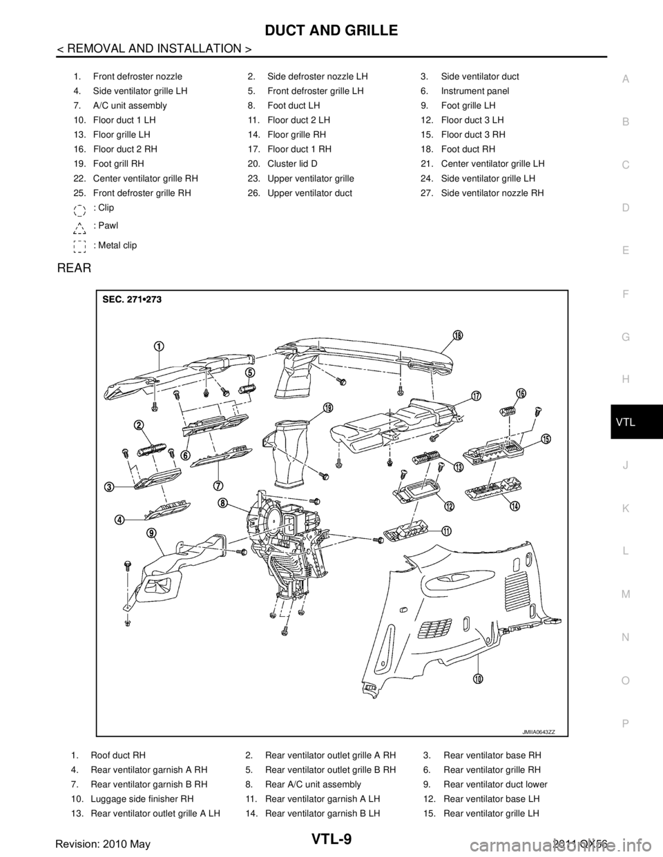
1. Front defroster nozzle 2. Side defroster nozzle LH 3. Side ventilator duct
4. Side ventilator grille LH 5. Front defroster grille LH 6. Instrument panel
7. A/C unit assembly 8. Foot duct LH 9. Foot grille LH
10. Floor duct 1 LH 11. Floor duct 2 LH 12. Floor duct 3 LH
13. Floor grille LH 14. Floor grille RH 15. Floor duct 3 RH
16. Floor duct 2 RH 17. Floor duct 1 RH 18. Foot duct RH
19. Foot grill RH 20. Cluster lid D 21. Center ventilator grille LH
22. Center ventilator grille RH 23. Upper ventilator grille 24. Side ventilator grille LH
25. Front defroster grille RH 26. Upper ventilator duct 27. Side ventilator nozzle RH : Clip
: Pawl
: Metal clip
1. Roof duct RH 2. Rear ventilator outlet grille A RH 3. Rear ventilator base RH
4. Rear ventilator garnish A RH 5. Rear ventilator outlet grille B RH 6. Rear ventilator grille RH
7. Rear ventilator garnish B RH 8. Rear A/C unit assembly 9. Rear ventilator duct lower
10. Luggage side finisher RH 11. Rear ventilator garnish A LH 12. Rear ventilator base LH
13. Rear ventilator outlet grille A LH 14. Rear ventilator garnish B LH 15. Rear ventilator grille LH
JMIIA0643ZZ
Revision: 2010 May2011 QX56
Page 5396 of 5598

VTL-10
< REMOVAL AND INSTALLATION >
DUCT AND GRILLE
CENTER VENTILAT O R G R I L L E
CENTER VENTILATOR GRILLE : Removal and InstallationINFOID:0000000006276287
REMOVAL
1. Remove cluster lid D. Refer to IP-14, "Removal and Installation".
2. Remove center ventilator grille from cluster lid D.
INSTALLATION
Install in the reverse order of removal.
SIDE VENTILATOR GRILLE
SIDE VENTILATOR GRILLE : Removal and InstallationINFOID:0000000006276288
REMOVAL
1. Remove instrument panel assembly. Refer to IP-14, "Removal and Installation".
2. Remove fixing screw, and then remove side ventilator grille from instrument panel.
INSTALLATION
Install in the reverse order of removal.
FRONT DEFROSTER GRILLE
FRONT DEFROSTER GRILLE : Removal and InstallationINFOID:0000000006276289
REMOVAL
Remove front defroster grilles, using remover tools.
INSTALLATION
Install in the reverse order of removal.
UPPER VENTILATOR GRILLE
UPPER VENTILATOR GRILLE : Removal and InstallationINFOID:0000000006276290
REMOVAL
Remove upper ventilator grille, using remover tools.
INSTALLATION
Install in the reverse order of removal.
SIDE VENTILATOR DUCT
SIDE VENTILATOR DUCT : Removal and InstallationINFOID:0000000006276291
REMOVAL
1. Remove instrument panel assembly. Refer to IP-14, "Removal and Installation".
2. Remove fixing screws, and then remove side ventilator duct from instrument panel.
INSTALLATION
Install in the reverse order of removal.
UPPER VENTILATOR DUCT
UPPER VENTILATOR DUCT : Removal and InstallationINFOID:0000000006276292
REMOVAL
1. Remove instrument panel assembly. Refer to IP-14, "Removal and Installation".
16. Rear ventilator outlet grille B LH 17. Roof duct LH Roof duct center
19. Rear ventilator duct upper
Revision: 2010 May2011 QX56
Page 5399 of 5598

DUCT AND GRILLEVTL-13
< REMOVAL AND INSTALLATION >
C
DE
F
G H
J
K L
M A
B
VTL
N
O P
ROOF DUCT
ROOF DUCT : Removal and InstallationINFOID:0000000006276303
REMOVAL
1. Remove headlining. Refer to INT-29, "Removal and Installation".
2. Remove mounting bolts and clip, and then remove roof duct (LH/RH).
3. Remove rear ventilator duct upper.
4. Remove roof duct (center).
INSTALLATION
Install in the reverse order of removal.
REAR VENTILATOR GRILLE
REAR VENTILATOR GRILLE : Removal and InstallationINFOID:0000000006276304
REMOVAL
1. Remove headlining. Refer to INT-29, "Removal and Installation".
2. Remove fixing screws, and then remove rear ventilator grille A and B from headlining.
INSTALLATION
Install in reverse order of removal.
Revision: 2010 May2011 QX56