2011 INFINITI QX56 clock
[x] Cancel search: clockPage 3140 of 5598
![INFINITI QX56 2011 Factory Service Manual
HAC-34
< SYSTEM DESCRIPTION >[AUTOMATIC AIR CONDITIONING]
OPERATION
DUAL switch Turns left and right ventilation temperature separately control (switch indicator) between ON
⇔
OFF each time.
W INFINITI QX56 2011 Factory Service Manual
HAC-34
< SYSTEM DESCRIPTION >[AUTOMATIC AIR CONDITIONING]
OPERATION
DUAL switch Turns left and right ventilation temperature separately control (switch indicator) between ON
⇔
OFF each time.
W](/manual-img/42/57033/w960_57033-3139.png)
HAC-34
< SYSTEM DESCRIPTION >[AUTOMATIC AIR CONDITIONING]
OPERATION
DUAL switch Turns left and right ventilation temperature separately control (switch indicator) between ON
⇔
OFF each time.
When DUAL switch indicator is ON, the driver side and passenger side temperatures can each be set independently.
When DUAL switch indicator is OFF, the driver side outlet and setting temperature is applied to both
sides.
Left and right ventilation temperature separately control is cancelled by turning the DEF mode ON.
NOTE:
When front air conditioning system is in the OFF position, left and right ventilation temperature sepa-
rately control can be selected only while front air conditioning system state (when MODE switch is
pressed) is indicated on the display.
Fan switch (UP/DOWN) Blower fan speed is manually controlled with these switches. Seven speeds are available for manual
control (as shown on the display screen)
NOTE:
When fan switch is pressed while front air conditioning system is in OFF, front air conditioning sys-
tem is activated. (Compressor control state returns to the previous state before front air condition-
ing system OFF.)
When fan switch is pressed while front air conditioning system is in automatic control (“AUTO” is
indicated), automatic control is released (“AUTO” turns OFF).
FRE switch Air inlet is selected to fresh air intake (FRE) by pressing this switch.
- FRE indicator: ON
- REC indicator: OFF
When FRE indicator is ON, pressing the FRE switch for approximately 1.5 seconds or more, and
then the FRE and REC switch indicators blink twice and the system is switched to the automatic
control.
NOTE:
When front air conditioning system is in the OFF position, air inlet can be selected.
MODE switch Selects air outlet sequentially from VENT
⇒ B/L ⇒ FOOT ⇒ D/F ⇒ VENT each time.
NOTE:
When front air conditioning system is in the OFF position, air outlet can be selected.
When MODE switch is pressed while front air conditioning system is in automatic control (“AUTO” is indicated), automatic control is released (“AUTO” turns OFF).
OFF switch Turns front air conditioning system OFF.
When front air conditioning system turns OFF, air inlet and air outlet become the automatic control.
REC switch Air inlet is selected to fresh air intake (REC) by pressing this switch.
- REC indicator: ON
- FRE indicator: OFF
When REC indicator is ON, pressing the REC switch for approximately 1.5 seconds or more, and
then the FRE and REC switch indicators blink twice and the system is switched to the automatic
control.
NOTE:
When front air conditioning system is in the OFF position, air inlet can be selected.
When MODE switch and DEF switch is in the D/F or DEF position, air inlet cannot be selected to recirculation (REC).
Temperature control dial
(driver side) Selects set temperature within a range between 18.0
°C (60 °F) – 32.0 °C (90 °F) at a rate of 0.5 °C
(1.0 °F) each time the dial is rotated.
- Clockwise rotation: Set temperature increases.
- Counterclockwise rotation: Set temperature decreases.
NOTE:
When front air conditioning system is in the OFF position, set temperature can be selected only while
front air conditioning system state (when MODE switch is pressed) is indicated on the display.
Revision: 2010 May2011 QX56
Page 3141 of 5598
![INFINITI QX56 2011 Factory Service Manual
OPERATIONHAC-35
< SYSTEM DESCRIPTION > [AUTOMATIC AIR CONDITIONING]
C
D
E
F
G H
J
K L
M A
B
HAC
N
O P
REAR AUTOMATIC AIR CONDITIONING SYSTEM
REAR AUTOMATIC AIR CONDITIONING SY STEM : Switch Name and INFINITI QX56 2011 Factory Service Manual
OPERATIONHAC-35
< SYSTEM DESCRIPTION > [AUTOMATIC AIR CONDITIONING]
C
D
E
F
G H
J
K L
M A
B
HAC
N
O P
REAR AUTOMATIC AIR CONDITIONING SYSTEM
REAR AUTOMATIC AIR CONDITIONING SY STEM : Switch Name and](/manual-img/42/57033/w960_57033-3140.png)
OPERATIONHAC-35
< SYSTEM DESCRIPTION > [AUTOMATIC AIR CONDITIONING]
C
D
E
F
G H
J
K L
M A
B
HAC
N
O P
REAR AUTOMATIC AIR CONDITIONING SYSTEM
REAR AUTOMATIC AIR CONDITIONING SY STEM : Switch Name and Function
INFOID:0000000006275882
FRONT CONTOLLER OPERATION
A/C Display
Rear air conditioning system state is indicated on the front display.
When REAR switch is pressed while air conditioning syst em is in the ON position, the front display changes
to state indication display (rear contro l mode) of rear air conditioning system.
Display screen
Controller (Preset Switch)
With ACCS (advanced climate control system)
Temperature control dial
(passenger side) Selects set temperature within a range between 18.0
°C (60 °F) – 32.0 °C (90 °F) at a rate of 0.5 °C
(1.0 °F) each time the dial is rotated.
- Clockwise rotation: Set temperature increases.
- Counterclockwise rotation: Set temperature decreases.
When the temperature control dial is turned, DUAL switch indicator turns ON.
NOTE:
When front air conditioning system is in the OFF position, set temperature can be selected only while
front air conditioning system state (when MODE switch is pressed) is indicated on the display.
Upper ventilator switch Turns the upper ventila
tor control (switch indicator) between ON ⇔ OFF each time while front blower
fan is activated.
NOTE:
When front air conditioning system is in the OFF position and air outlet is DEF position, upper ven- tilator control cannot be activated.
When front air conditioning system is in the OFF position, upper ventilator control can be selected only while front air conditioning system state (when MODE switch is pressed) is indicated on the
display.
JMIIA0720ZZ
JMIIA0825ZZ
1. AUTO switch 2. Temperature control dial (Driver
side)3. MODE switch
4. REAR switch 5. OFF switch 6. Fan switch
Revision: 2010 May2011 QX56
Page 3142 of 5598
![INFINITI QX56 2011 Factory Service Manual
HAC-36
< SYSTEM DESCRIPTION >[AUTOMATIC AIR CONDITIONING]
OPERATION
Without ACCS (advanced
climate control system)
Switch Operation
REAR CONTROLLER OPERATION
Controller (Rear A/C Control)
JMIIA0824Z INFINITI QX56 2011 Factory Service Manual
HAC-36
< SYSTEM DESCRIPTION >[AUTOMATIC AIR CONDITIONING]
OPERATION
Without ACCS (advanced
climate control system)
Switch Operation
REAR CONTROLLER OPERATION
Controller (Rear A/C Control)
JMIIA0824Z](/manual-img/42/57033/w960_57033-3141.png)
HAC-36
< SYSTEM DESCRIPTION >[AUTOMATIC AIR CONDITIONING]
OPERATION
Without ACCS (advanced
climate control system)
Switch Operation
REAR CONTROLLER OPERATION
Controller (Rear A/C Control)
JMIIA0824ZZ
1. AUTO switch 2. Temperature control dial (Driver
side)3. MODE switch
4. REAR switch 5. OFF switch 6. Fan switch
AUTO switch Turns the switch indicator lamp and "AUTO" indicator on the front display ON, and then rear air con-
ditioning system becomes the following state.
Air outlet: Automatic control
Blower fan: Automatic control
Compressor: ON
Fan switch (UP/DOWN) Blower fan speed is manually controlled with these switches. Seven speeds are available for manual
control (as shown on the display screen)
NOTE:
When fan switch is pressed while air conditioning system is in automatic control (“AUTO” is indicated),
automatic control is rele
ased (“AUTO” turns OFF).
MODE switch Selects air outlet sequentially from VENT
⇒ B/L ⇒ FOOT ⇒ VENT each time.
NOTE:
When MODE switch is pressed while air conditioning system is in automatic control (“AUTO” is indi-
cated), automatic control is released (“AUTO” turns OFF).
OFF switch Turns rear air conditioning system OFF. (When rear control mode is ON)
When rear air conditioning system turns OFF, air outlet become the automatic control.
REAR switch Turns the switch indicator lamp and rear control mode on the front display ON, and then rear air
conditioning system becomes the following state.
- Air outlet: Automatic control
- Blower fan: Automatic control
- Compressor: ON
Rear control mode is released when switch is pressed again (rear air conditioning system operates continuously).
Temperature control dial
(driver side) Selects set temperature within a range between 18.0
°C (60 °F) – 32.0 °C (90 °F) at a rate of 0.5 °C
(1.0 °F) each time the dial is rotated.
- Clockwise rotation: Set temperature increases.
- Counterclockwise rotation: Set temperature decreases.
Revision: 2010 May2011 QX56
Page 3337 of 5598
INL-70
< REMOVAL AND INSTALLATION >
GLOVE BOX LAMP
GLOVE BOX LAMP
Exploded ViewINFOID:0000000006288647
ReplacementINFOID:0000000006288648
CAUTION:
Disconnect the battery cable from negative terminal or remove the fuse.
Never touch the glass of bulb directly by hand. Keep grease and other oily substaces away from it.
Never touch bulb by hand while it is lit or right after it is off.
Never leave bulb out of lamp reflector for a long ti me because dust, moisture smoke, etc. may affect
the performance of lamp. When replacing bu lb, be sure to replace it with a new one.
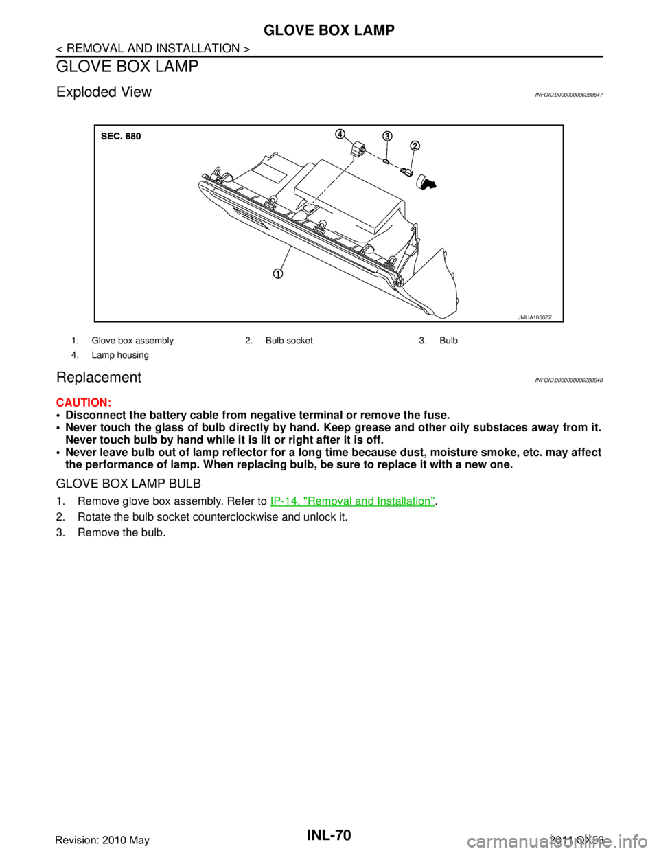
GLOVE BOX LAMP BULB
1. Remove glove box assembly. Refer to IP-14, "Removal and Installation".
2. Rotate the bulb socket counterclockwise and unlock it.
3. Remove the bulb.
1. Glove box assembly 2. Bulb socket 3. Bulb
4. Lamp housing
JMLIA1050ZZ
Revision: 2010 May2011 QX56
Page 3338 of 5598
FOOT LAMPINL-71
< REMOVAL AND INSTALLATION >
C
DE
F
G H
I
J
K
M A
B
INL
N
O P
FOOT LAMP
DRIVER SIDE
DRIVER SIDE : Exploded ViewINFOID:0000000006288649
DRIVER SIDE : ReplacementINFOID:0000000006288650
CAUTION:
Disconnect the battery cable from negative terminal or remove the fuse.
Never touch the glass of bulb directly by hand. Keep grease and other oily substaces away from it.
Never touch bulb by hand while it is lit or right after it is off.
Never leave bulb out of lamp reflector for a long time because dust, moisture smoke, etc. may affect
the performance of lamp. When replacing bu lb, be sure to replace it with a new one.
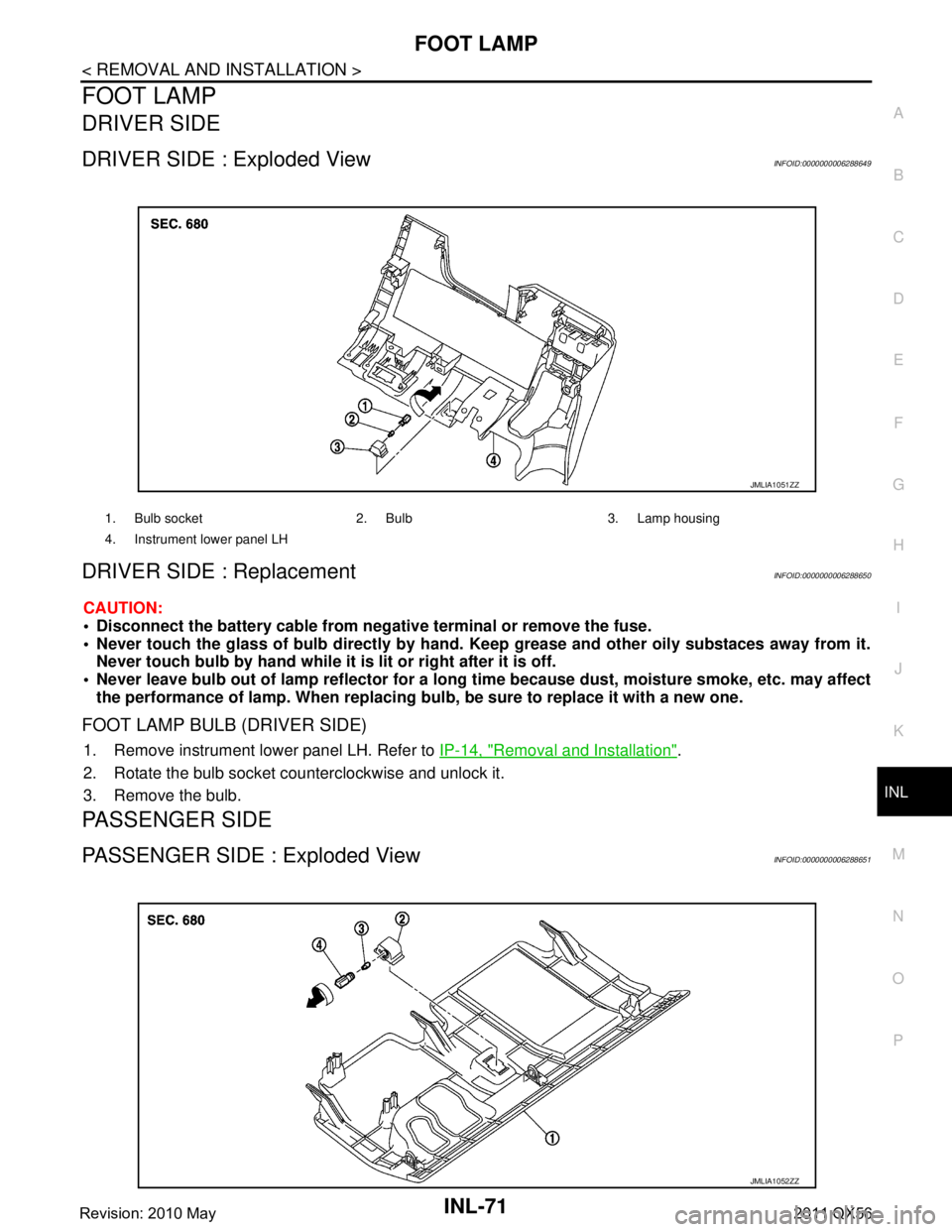
FOOT LAMP BULB (DRIVER SIDE)
1. Remove instrument lower panel LH. Refer to IP-14, "Removal and Installation".
2. Rotate the bulb socket counterclockwise and unlock it.
3. Remove the bulb.
PASSENGER SIDE
PASSENGER SIDE : Exploded ViewINFOID:0000000006288651
1. Bulb socket 2. Bulb 3. Lamp housing
4. Instrument lower panel LH
JMLIA1051ZZ
JMLIA1052ZZ
Revision: 2010 May2011 QX56
Page 3339 of 5598
INL-72
< REMOVAL AND INSTALLATION >
FOOT LAMP
PASSENGER SIDE : Replacement
INFOID:0000000006288652
CAUTION:
Disconnect the battery cable from negative terminal or remove the fuse.
Never touch the glass of bulb directly by hand. Keep grease and other oily substaces away from it.
Never touch bulb by hand while it is lit or right after it is off.
Never leave bulb out of lamp reflector for a long ti me because dust, moisture smoke, etc. may affect
the performance of lamp. When replacing bu lb, be sure to replace it with a new one.
FOOT LAMP BULB (PASSENGER SIDE)
1. Remove instrument lower cover. Refer to IP-14, "Removal and Installation".
2. Rotate the bulb socket counterclockwise and unlock it.
3. Remove the bulb.
REAR FOOT LAMP
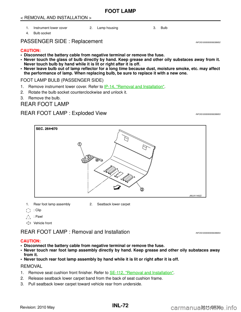
REAR FOOT LAMP : Exploded ViewINFOID:0000000006288653
REAR FOOT LAMP : Re moval and InstallationINFOID:0000000006288654
CAUTION:
Disconnect the battery cable from negative terminal or remove the fuse.
Never touch rear foot lamp assembly directly by hand. Keep grease and other oily substaces away
from it.
Never touch rear foot lamp assembly by hand while it is lit or right after it is off.
REMOVAL
1. Remove seat cushion front finisher. Refer to SE-112, "Removal and Installation".
2. Release seatback lower carpet band fr om the back of seat cushion frame.
3. Pull seatback lower carpet toward vehicle rear from underside.
1. Instrument lower cover 2. Lamp housing 3. Bulb
4. Bulb socket
1. Rear foot lamp assembly 2. Seatback lower carpet
: Clip
: Pawl
Vehicle front
JMLIA1149ZZ
Revision: 2010 May2011 QX56
Page 3356 of 5598
SQUEAK AND RATTLE TROUBLE DIAGNOSESINT-7
< SYMPTOM DIAGNOSIS >
C
DE
F
G H
I
K L
M A
B
INT
N
O P
SYMPTOM DIAGNOSIS
SQUEAK AND RATTLE TROUBLE DIAGNOSES
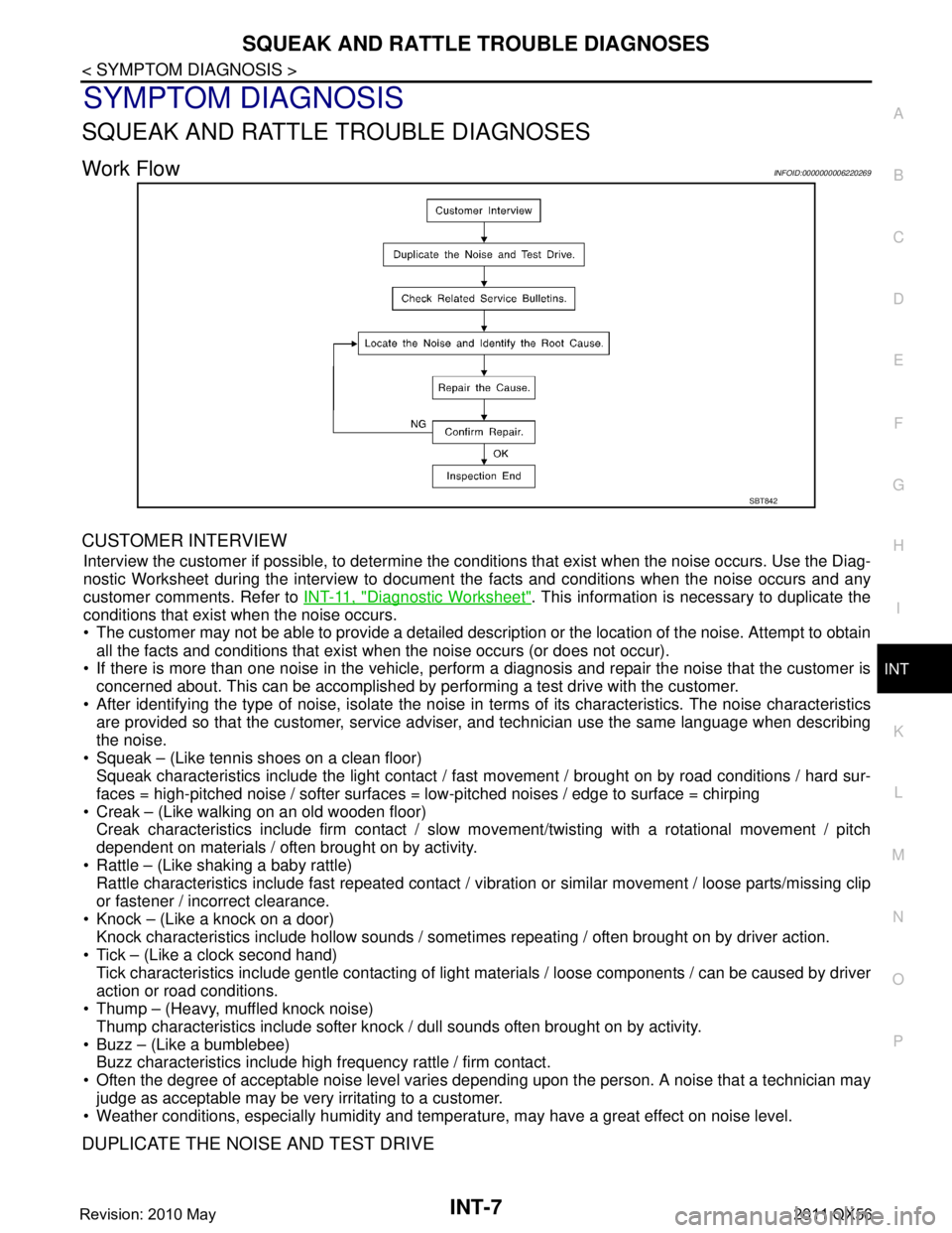
Work FlowINFOID:0000000006220269
CUSTOMER INTERVIEW
Interview the customer if possible, to determine the conditions that exist when the noise occurs. Use the Diag-
nostic Worksheet during the interv iew to document the facts and conditions when the noise occurs and any
customer comments. Refer to INT-11, "
Diagnostic Worksheet". This information is necessary to duplicate the
conditions that exist when the noise occurs.
The customer may not be able to provide a detailed description or the location of the noise. Attempt to obtain
all the facts and conditions that exist when the noise occurs (or does not occur).
If there is more than one noise in the vehicle, perform a diagnosis and repair the noise that the customer is
concerned about. This can be accomplished by performing a test drive with the customer.
After identifying the type of noise, isolate the noise in terms of its characteristics. The noise characteristics
are provided so that the customer, service advis er, and technician use the same language when describing
the noise.
Squeak – (Like tennis shoes on a clean floor) Squeak characteristics include the light contact / fast movement / brought on by road conditions / hard sur-
faces = high-pitched noise / softer surfaces = low-pitched noises / edge to surface = chirping
Creak – (Like walking on an old wooden floor) Creak characteristics include firm contact / slow mo vement/twisting with a rotational movement / pitch
dependent on materials / often brought on by activity.
Rattle – (Like shaking a baby rattle) Rattle characteristics include fast repeated contact / vi bration or similar movement / loose parts/missing clip
or fastener / incorrect clearance.
Knock – (Like a knock on a door) Knock characteristics include hollow sounds / someti mes repeating / often brought on by driver action.
Tick – (Like a clock second hand) Tick characteristics include gentle contacting of light materials / loose components / can be caused by driver
action or road conditions.
Thump – (Heavy, muffled knock noise)
Thump characteristics include softer knock / dull sounds often brought on by activity.
Buzz – (Like a bumblebee) Buzz characteristics include high frequency rattle / firm contact.
Often the degree of acceptable noise level varies depending upon the person. A noise that a technician may
judge as acceptable may be very irritating to a customer.
Weather conditions, especially humidity and temperat ure, may have a great effect on noise level.
DUPLICATE THE NOISE AND TEST DRIVE
SBT842
Revision: 2010 May2011 QX56
Page 3397 of 5598
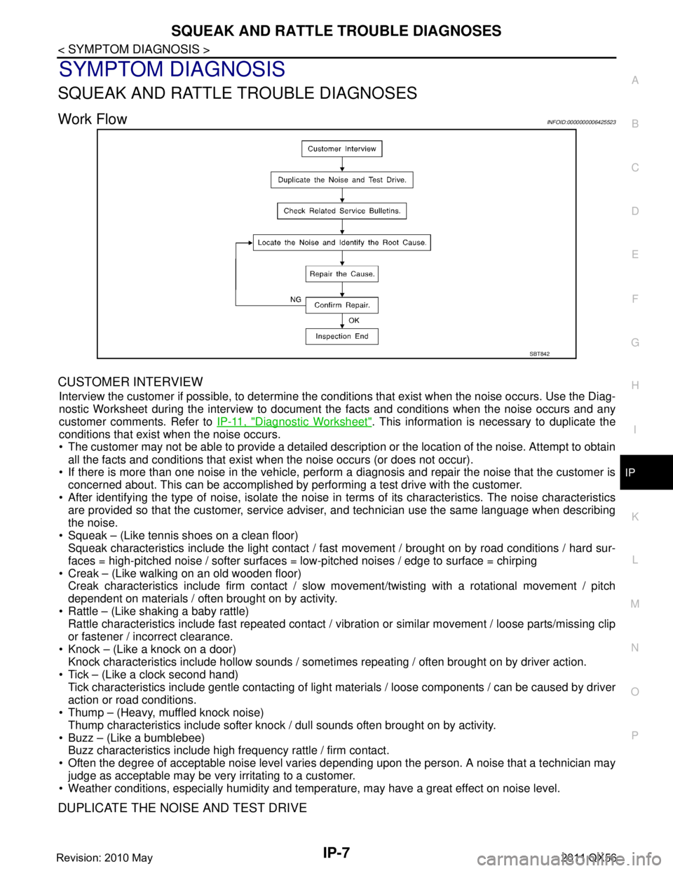
SQUEAK AND RATTLE TROUBLE DIAGNOSESIP-7
< SYMPTOM DIAGNOSIS >
C
DE
F
G H
I
K L
M A
B
IP
N
O P
SYMPTOM DIAGNOSIS
SQUEAK AND RATTLE TROUBLE DIAGNOSES
Work FlowINFOID:0000000006425523
CUSTOMER INTERVIEW
Interview the customer if possible, to determine the conditions that exist when the noise occurs. Use the Diag-
nostic Worksheet during the interv iew to document the facts and conditions when the noise occurs and any
customer comments. Refer to IP-11, "
Diagnostic Worksheet". This information is necessary to duplicate the
conditions that exist when the noise occurs.
The customer may not be able to provide a detailed description or the location of the noise. Attempt to obtain
all the facts and conditions that exist when the noise occurs (or does not occur).
If there is more than one noise in the vehicle, perform a diagnosis and repair the noise that the customer is
concerned about. This can be accomplished by performing a test drive with the customer.
After identifying the type of noise, isolate the noise in terms of its characteristics. The noise characteristics
are provided so that the customer, service advis er, and technician use the same language when describing
the noise.
Squeak – (Like tennis shoes on a clean floor) Squeak characteristics include the light contact / fast movement / brought on by road conditions / hard sur-
faces = high-pitched noise / softer surfaces = low-pitched noises / edge to surface = chirping
Creak – (Like walking on an old wooden floor) Creak characteristics include firm contact / slow mo vement/twisting with a rotational movement / pitch
dependent on materials / often brought on by activity.
Rattle – (Like shaking a baby rattle) Rattle characteristics include fast repeated contact / vi bration or similar movement / loose parts/missing clip
or fastener / incorrect clearance.
Knock – (Like a knock on a door) Knock characteristics include hollow sounds / someti mes repeating / often brought on by driver action.
Tick – (Like a clock second hand) Tick characteristics include gentle contacting of light materials / loose components / can be caused by driver
action or road conditions.
Thump – (Heavy, muffled knock noise)
Thump characteristics include softer knock / dull sounds often brought on by activity.
Buzz – (Like a bumblebee) Buzz characteristics include high frequency rattle / firm contact.
Often the degree of acceptable noise level varies depending upon the person. A noise that a technician may
judge as acceptable may be very irritating to a customer.
Weather conditions, especially humidity and temperat ure, may have a great effect on noise level.
DUPLICATE THE NOISE AND TEST DRIVE
SBT842
Revision: 2010 May2011 QX56