2011 INFINITI QX56 clock
[x] Cancel search: clockPage 2934 of 5598
FUEL LEVEL SENSOR UNIT, FUEL FILTER AND FUEL PUMP ASSEMBLY
FL-5
< REMOVAL AND INSTALLATION >
C
D E
F
G H
I
J
K L
M A
FL
NP
O
REMOVAL AND INSTALLATION
FUEL LEVEL SENSOR UNIT, FUEL FI
LTER AND FUEL PUMP ASSEMBLY
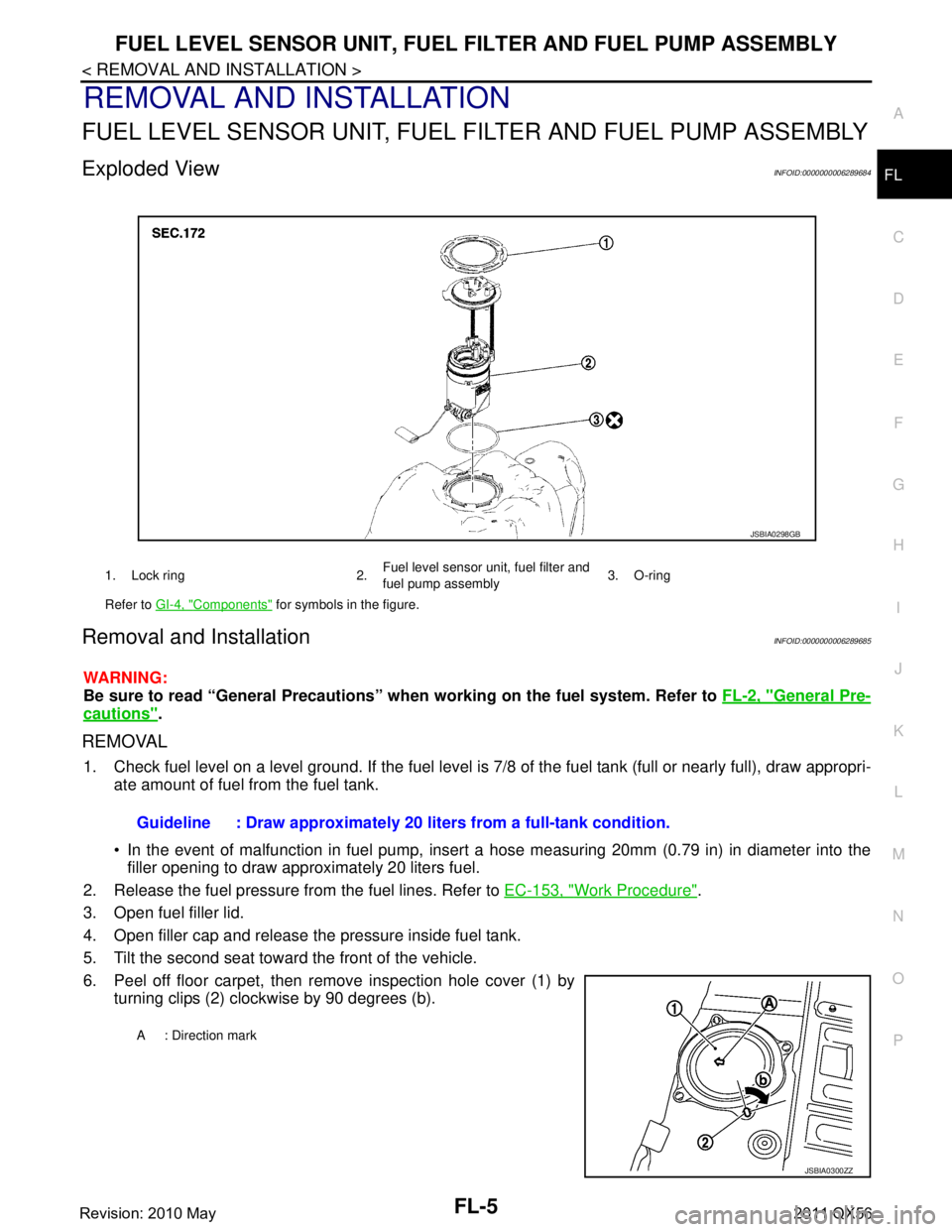
Exploded ViewINFOID:0000000006289684
Removal and InstallationINFOID:0000000006289685
WARNING:
Be sure to read “General Precautions” wh en working on the fuel system. Refer to FL-2, "
General Pre-
cautions".
REMOVAL
1. Check fuel level on a level ground. If the fuel level is 7/8 of the fuel tank (full or nearly full), draw appropri-
ate amount of fuel from the fuel tank.
In the event of malfunction in fuel pump, insert a hose measuring 20mm (0.79 in) in diameter into the
filler opening to draw approximately 20 liters fuel.
2. Release the fuel pressure from the fuel lines. Refer to EC-153, "
Work Procedure".
3. Open fuel filler lid.
4. Open filler cap and release the pressure inside fuel tank.
5. Tilt the second seat toward the front of the vehicle.
6. Peel off floor carpet, then remove inspection hole cover (1) by turning clips (2) clockwise by 90 degrees (b).
1. Lock ring 2. Fuel level sensor unit, fuel filter and
fuel pump assembly3. O-ring
Refer to GI-4, "
Components" for symbols in the figure.
JSBIA0298GB
Guideline : Draw approximately 20 li ters from a full-tank condition.
A : Direction mark
JSBIA0300ZZ
Revision: 2010 May2011 QX56
Page 2936 of 5598
FUEL LEVEL SENSOR UNIT, FUEL FILTER AND FUEL PUMP ASSEMBLY
FL-7
< REMOVAL AND INSTALLATION >
C
D E
F
G H
I
J
K L
M A
FL
NP
O
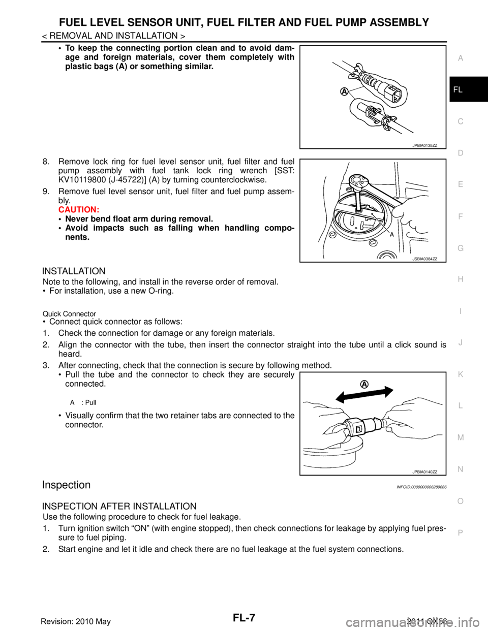
To keep the connecting portio
n clean and to avoid dam-
age and foreign materials, cover them completely with
plastic bags (A) or something similar.
8. Remove lock ring for fuel level sensor unit, fuel filter and fuel pump assembly with fuel tank lock ring wrench [SST:
KV10119800 (J-45722)] (A) by turning counterclockwise.
9. Remove fuel level sensor unit, fuel filter and fuel pump assem- bly.
CAUTION:
Never bend float arm during removal.
Avoid impacts such as fa lling when handling compo-
nents.
INSTALLATION
Note to the following, and install in the reverse order of removal.
For installation, use a new O-ring.
Quick Connector Connect quick connector as follows:
1. Check the connection for damage or any foreign materials.
2. Align the connector with the tube, then insert the connector straight into the tube until a click sound is
heard.
3. After connecting, check that the connection is secure by following method. Pull the tube and the connector to check they are securely
connected.
Visually confirm that the two retainer tabs are connected to the connector.
InspectionINFOID:0000000006289686
INSPECTION AFTER INSTALLATION
Use the following procedure to check for fuel leakage.
1. Turn ignition switch “ON” (with engine stopped), then check connections for leakage by applying fuel pres-
sure to fuel piping.
2. Start engine and let it idle and check there are no fuel leakage at the fuel system connections.
JPBIA0135ZZ
JSBIA0384ZZ
A: Pull
JPBIA0140ZZ
Revision: 2010 May2011 QX56
Page 2941 of 5598
FL-12
< REMOVAL AND INSTALLATION >
EVAP CANISTER
Removal and Installation
INFOID:0000000006414454
REMOVAL
1. Remove the spare tire.
2. Disconnect harness connectors and hoses.
3. Remove EVAP canister fixing bolt.
4. Remove EVAP canister.
NOTE:
The EVAP canister vent control valve and EVAP cont rol system pressure sensor can be removed without
removing the EVAP canister.
INSTALLATION
Install in the reverse order of removal.
NOTE:
Tighten EVAP canister fixing bolt to the specified torque.
Disassembly and AssemblyINFOID:0000000006414455
DISASSEMBLY
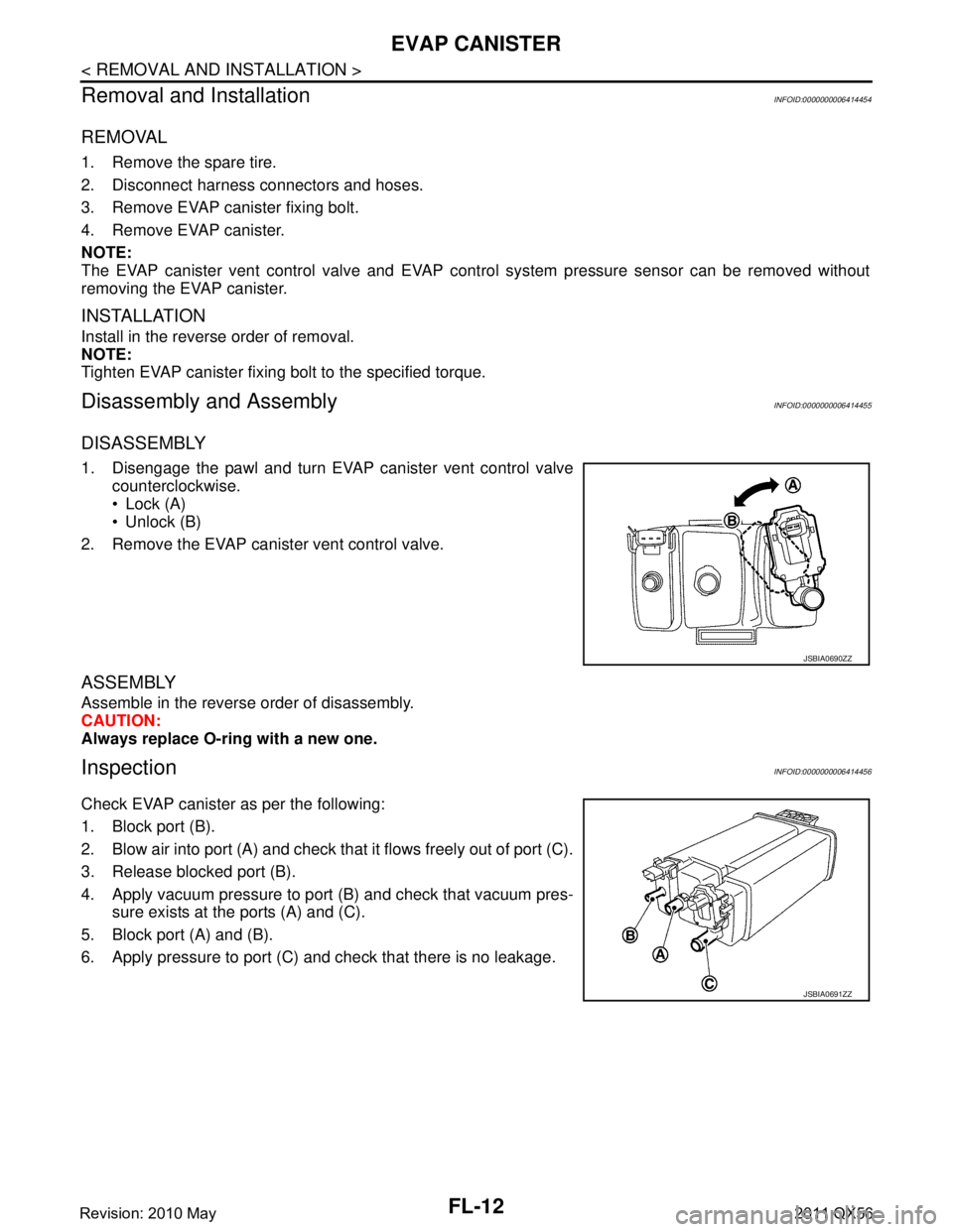
1. Disengage the pawl and turn EVAP canister vent control valve counterclockwise.
Lock (A)
Unlock (B)
2. Remove the EVAP canister vent control valve.
ASSEMBLY
Assemble in the reverse order of disassembly.
CAUTION:
Always replace O-ring with a new one.
InspectionINFOID:0000000006414456
Check EVAP canister as per the following:
1. Block port (B).
2. Blow air into port (A) and check that it flows freely out of port (C).
3. Release blocked port (B).
4. Apply vacuum pressure to port (B) and check that vacuum pres- sure exists at the ports (A) and (C).
5. Block port (A) and (B).
6. Apply pressure to port (C) and check that there is no leakage.
JSBIA0690ZZ
JSBIA0691ZZ
Revision: 2010 May2011 QX56
Page 2981 of 5598

ABBREVIATIONSGI-17
< HOW TO USE THIS MANUAL >
C
DE
F
G H
I
J
K L
M B
GI
N
O P
P
R
S
T
V
W
1
ABBREVIATION DESCRIPTION P/S Power steering
PBR Potentio balance resistor
PCV Positive crankcase ventilation
PNP Park/Neutral position PSP Power steering pressurePTC Positive temperature coefficient
PTO Power takeoff
PWM Pulse width modulation
ABBREVIATION DESCRIPTION RAM Random access memoryRAS Rear active steer RH Right-hand
ROM Read only memory RPM Engine speed RR Rear
ABBREVIATION DESCRIPTION SAE Society of Automoti ve Engineers, Inc.
SCK Serial clock
SDS Service Data and Specifications SRT System readiness testSST Special Service Tools
ABBREVIATION DESCRIPTION TC Turbocharger
TCM Transmission control module TCS Traction control system TP Throttle position
TPMS Tire pressure monitoring system TSS Turbine shaft speed
TWC Three way catalytic converter
ABBREVIATION DESCRIPTION VDC Vehicle dynamics control systemVIN Vehicle identification number
VSS Vehicle speed sensor
ABBREVIATION DESCRIPTION WOT Wide open throttle
ABBREVIATION DESCRIPTION 1
11st range first gear
Revision: 2010 May2011 QX56
Page 3034 of 5598
SQUEAK AND RATTLE TROUBLE DIAGNOSESGW-5
< SYMPTOM DIAGNOSIS >
C
DE
F
G H
I
J
L
M A
B
GW
N
O P
SYMPTOM DIAGNOSIS
SQUEAK AND RATTLE TROUBLE DIAGNOSES
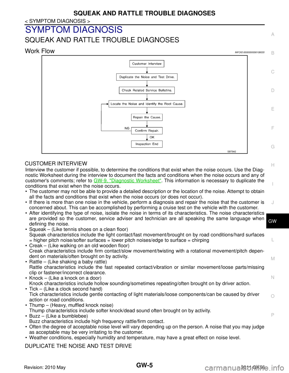
Work FlowINFOID:0000000006108035
CUSTOMER INTERVIEW
Interview the customer if possible, to determine the conditions that exist when the noise occurs. Use the Diag-
nostic Worksheet during the interview to document t he facts and conditions when the noise occurs and any of
customer's comments; refer to GW-9, "
Diagnostic Worksheet". This information is necessary to duplicate the
conditions that exist when the noise occurs.
The customer may not be able to provide a detailed description or the location of the noise. Attempt to obtain
all the facts and conditions that exist when the noise occurs (or does not occur).
If there is more than one noise in the vehicle, perform a diagnosis and repair the noise that the customer is
concerned about. This can be accomplished by performing a cruise test on the vehicle with the customer.
After identifying the type of noise, isolate the noise in terms of its characteristics. The noise characteristics
are provided so the customer, service adviser and technician are all speaking the same language when
defining the noise.
Squeak – (Like tennis shoes on a clean floor) Squeak characteristics include the light contact/fast movement/brought on by road conditions/hard surfaces
= higher pitch noise/softer surfaces = lower pitch noises/edge to surface = chirping
Creak – (Like walking on an old wooden floor) Creak characteristics include firm contact/slow mo vement/twisting with a rotational movement/pitch depen-
dent on materials/often brought on by activity.
Rattle – (Like shaking a baby rattle) Rattle characteristics include the fast repeated contac t/vibration or similar movement/loose parts/missing
clip or fastener/incorrect clearance.
Knock – (Like a knock on a door) Knock characteristics include hollow sounding/someti mes repeating/often brought on by driver action.
Tick – (Like a clock second hand) Tick characteristics include gentle contacting of li ght materials/loose components/can be caused by driver
action or road conditions.
Thump – (Heavy, muffled knock noise)
Thump characteristics include softer k nock/dead sound often brought on by activity.
Buzz – (Like a bumblebee) Buzz characteristics include high frequency rattle/firm contact.
Often the degree of acceptable noise level will vary depending up on the person. A noise that you may judge
as acceptable may be very irritating to the customer.
Weather conditions, especially humidity and temperat ure, may have a great effect on noise level.
DUPLICATE THE NOISE AND TEST DRIVE
SBT842
Revision: 2010 May2011 QX56
Page 3064 of 5598
HA-8
< PRECAUTION >
PRECAUTIONS
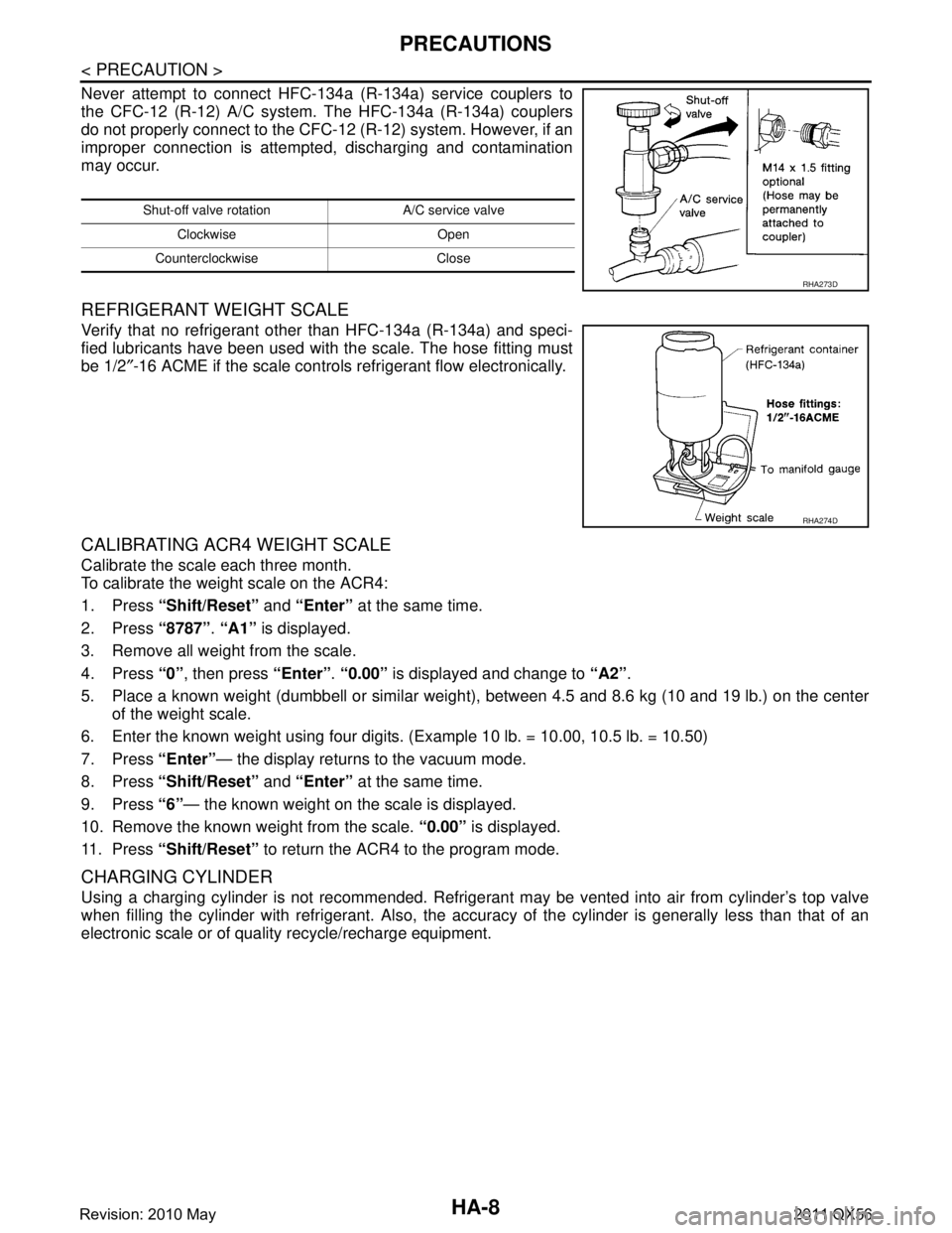
Never attempt to connect HFC-134a (R-134a) service couplers to
the CFC-12 (R-12) A/C system. The HFC-134a (R-134a) couplers
do not properly connect to the CFC-12 (R-12) system. However, if an
improper connection is attempted, discharging and contamination
may occur.
REFRIGERANT WEIGHT SCALE
Verify that no refrigerant other than HFC-134a (R-134a) and speci-
fied lubricants have been used with the scale. The hose fitting must
be 1/2″-16 ACME if the scale controls refrigerant flow electronically.
CALIBRATING ACR4 WEIGHT SCALE
Calibrate the scale each three month.
To calibrate the weight scale on the ACR4:
1. Press “Shift/Reset” and “Enter” at the same time.
2. Press “8787”. “A1” is displayed.
3. Remove all weight from the scale.
4. Press “0”, then press “Enter”. “0.00” is displayed and change to “A2”.
5. Place a known weight (dumbbell or similar weight ), between 4.5 and 8.6 kg (10 and 19 lb.) on the center
of the weight scale.
6. Enter the known weight using four digi ts. (Example 10 lb. = 10.00, 10.5 lb. = 10.50)
7. Press “Enter”— the display returns to the vacuum mode.
8. Press “Shift/Reset” and “Enter” at the same time.
9. Press “6”— the known weight on the scale is displayed.
10. Remove the known weight from the scale. “0.00” is displayed.
11. Press “Shift/Reset” to return the ACR4 to the program mode.
CHARGING CYLINDER
Using a charging cylinder is not recommended. Refrigerant may be vented into air from cylinder’s top valve
when filling the cylinder with refrigerant. Also, the accu racy of the cylinder is generally less than that of an
electronic scale or of quality recycle/recharge equipment.
Shut-off valve rotati on A/C service valve
Clockwise Open
Counterclockwise Close
RHA273D
RHA274D
Revision: 2010 May2011 QX56
Page 3106 of 5598
HA-50
< SERVICE DATA AND SPECIFICATIONS (SDS)
SERVICE DATA AND SPECIFICATIONS (SDS)
SERVICE DATA AND SPECIFICATIONS (SDS)
SERVICE DATA AND SPECIFICATIONS (SDS)
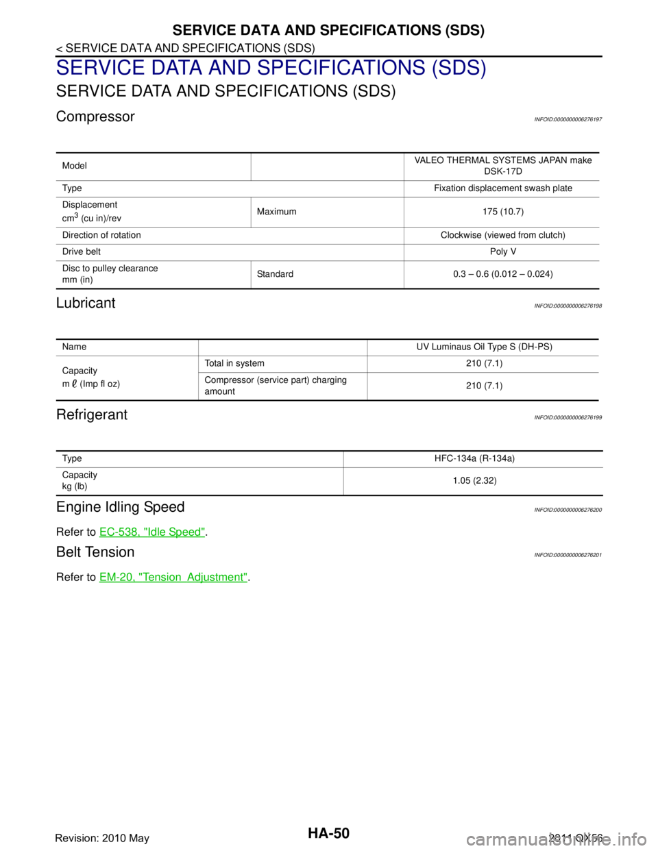
CompressorINFOID:0000000006276197
LubricantINFOID:0000000006276198
RefrigerantINFOID:0000000006276199
Engine Idling SpeedINFOID:0000000006276200
Refer to EC-538, "Idle Speed".
Belt TensionINFOID:0000000006276201
Refer to EM-20, "TensionAdjustment".
Model VALEO THERMAL SYSTEMS JAPAN make
DSK-17D
Ty p e Fixation displacement swash plate
Displacement
cm
3 (cu in)/rev Maximum 175 (10.7)
Direction of rotation Clockwise (viewed from clutch)
Drive belt Poly V
Disc to pulley clearance
mm (in) Standard 0.3 – 0.6 (0.012 – 0.024)
Name
UV Luminaus Oil Type S (DH-PS)
Capacity
m (Imp fl oz) Total in system 210 (7.1)
Compressor (service part) charging
amount
210 (7.1)
Ty p e
HFC-134a (R-134a)
Capacity
kg (lb) 1.05 (2.32)
Revision: 2010 May2011 QX56
Page 3138 of 5598
![INFINITI QX56 2011 Factory Service Manual
HAC-32
< SYSTEM DESCRIPTION >[AUTOMATIC AIR CONDITIONING]
OPERATION
WITHOUT ACCS (ADVANCED CLIMATE CONTROL SYSTEM)
A/C Display
Front air conditioning system state is indicated on the display.
Whe INFINITI QX56 2011 Factory Service Manual
HAC-32
< SYSTEM DESCRIPTION >[AUTOMATIC AIR CONDITIONING]
OPERATION
WITHOUT ACCS (ADVANCED CLIMATE CONTROL SYSTEM)
A/C Display
Front air conditioning system state is indicated on the display.
Whe](/manual-img/42/57033/w960_57033-3137.png)
HAC-32
< SYSTEM DESCRIPTION >[AUTOMATIC AIR CONDITIONING]
OPERATION
WITHOUT ACCS (ADVANCED CLIMATE CONTROL SYSTEM)
A/C Display
Front air conditioning system state is indicated on the display.
When “STATUS” on multifunction switch is pressed while
front air conditioning system is in the ON position,
the display changes to state indication display of fr ont air conditioning system. When front air conditioning
system is operated while navigation system or audio system is displayed, front air conditioning system state
is indicated in the lower portion of display for several seconds.
When MODE switch is pressed while front air conditioni ng system is in the OFF position, state indication dis-
play is indicated for several seconds.
Display Screen
Controller (Preset Switch)
Intake switch Air inlet changes between recirculation (REC)
⇔ fresh air intake (FRE) each time this switch is
pressed.
Intake switch indicator ON: Recirculation
Intake switch indicator OFF: Fresh air intake
NOTE:
When front air conditioning system is in the OFF position, air inlet can be selected.
When MODE switch and DEF switch is in the D/F or DEF position, air inlet cannot be selected to recirculation (REC).
Temperature control dial
(driver side) Selects set temperature within a range between 18.0
°C (60 °F) – 32.0 °C (90 °F) at a rate of 0.5 °C
(1.0 °F) each time the dial is rotated.
- Clockwise rotation: Set temperature increases.
- Counterclockwise rotation: Set temperature decreases.
NOTE:
When front air conditioning system is in the OFF position, set temperature can be selected only while
front air conditioning system state (when MODE switch is pressed) is indicated on the display.
Temperature control dial
(passenger side) Selects set temperature within a range between 18.0
°C (60 °F) – 32.0 °C (90 °F) at a rate of 0.5 °C
(1.0 °F) each time the dial is rotated.
- Clockwise rotation: Set temperature increases.
- Counterclockwise rotation: Set temperature decreases.
When the temperature control dial is turned, DUAL switch indicator turns ON.
NOTE:
When front air conditioning system is in the OFF position, set temperature can be selected only while
front air conditioning system state (when MODE switch is pressed) is indicated on the display.
Upper ventilator switch Turns the upper ventilator control (switch indicator) between ON
⇔ OFF each time while front blower
fan is activated.
NOTE:
When front air conditioning system is in the OFF position and air outlet is DEF position, upper ven- tilator control cannot be activated.
When front air conditioning system is in the OFF position, upper ventilator control can be selected
only while front air conditioning system state (when MODE switch is pressed) is indicated on the
display.
JMIIA0719GB
Revision: 2010 May2011 QX56