2011 INFINITI QX56 clock
[x] Cancel search: clockPage 3831 of 5598
MWI-88
< REMOVAL AND INSTALLATION >
CLOCK
CLOCK
Exploded ViewINFOID:0000000006221783
REMOVAL
Refer to IP-13, "Exploded View".
Removal and InstallationINFOID:0000000006221784
REMOVAL
1. Remove cluster lid C assembly. Refer to IP-14, "Removal and Installation".
2. Disengage the tabs to separate clock.
INSTALLATION
Install in the reverse order of removal.
Revision: 2010 May2011 QX56
Page 4240 of 5598
RF-26
< SYMPTOM DIAGNOSIS >
SQUEAK AND RATTLE TROUBLE DIAGNOSES
SQUEAK AND RATTLE TROUBLE DIAGNOSES
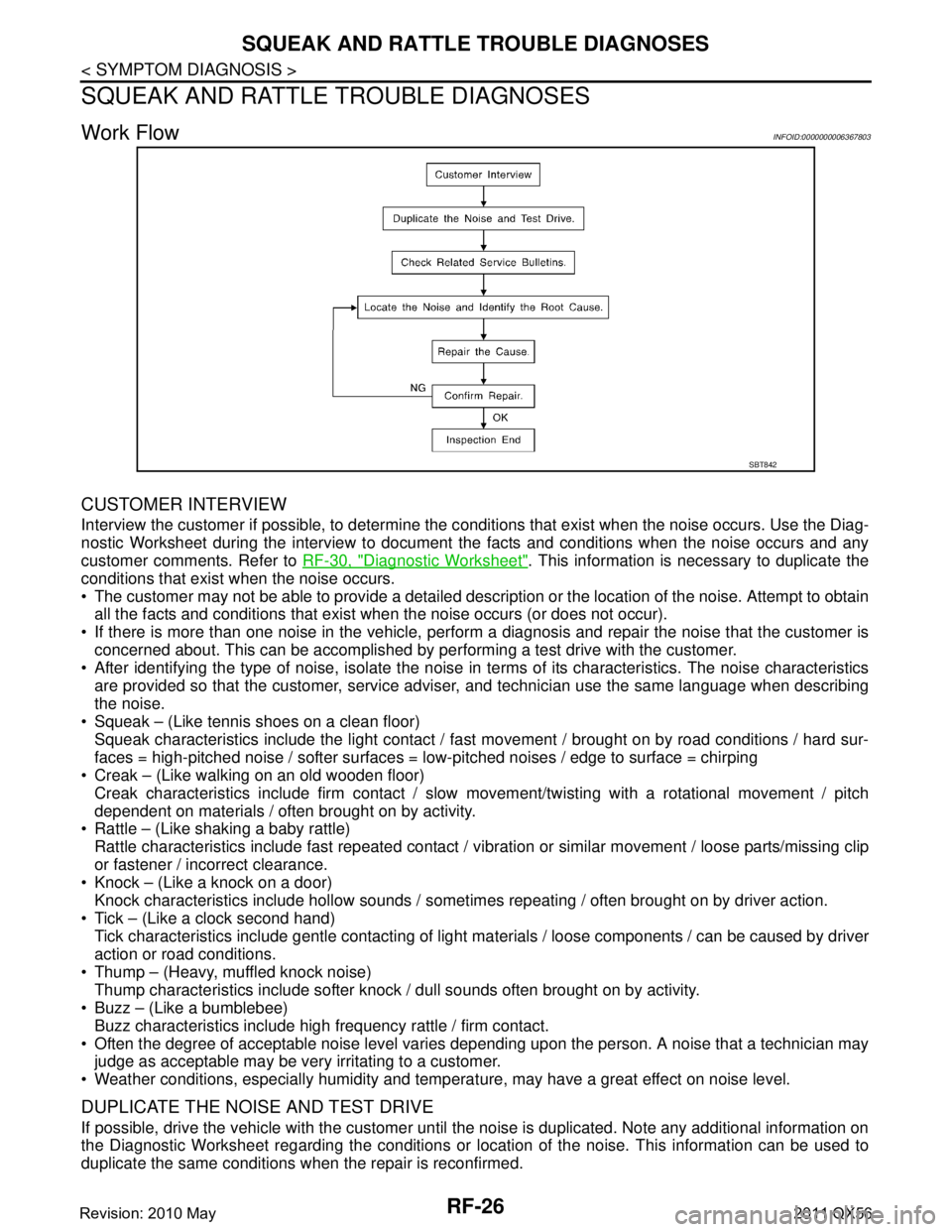
Work FlowINFOID:0000000006367803
CUSTOMER INTERVIEW
Interview the customer if possible, to determine the c onditions that exist when the noise occurs. Use the Diag-
nostic Worksheet during the interview to document the facts and conditions when the noise occurs and any
customer comments. Refer to RF-30, "
Diagnostic Worksheet". This information is necessary to duplicate the
conditions that exist when the noise occurs.
The customer may not be able to provide a detailed description or the location of the noise. Attempt to obtain all the facts and conditions that exist w hen the noise occurs (or does not occur).
If there is more than one noise in the vehicle, perform a diagnosis and repair the noise that the customer is
concerned about. This can be accomplished by per forming a test drive with the customer.
After identifying the type of noise, isolate the noise in terms of its characteristics. The noise characteristics
are provided so that the customer, service advis er, and technician use the same language when describing
the noise.
Squeak – (Like tennis shoes on a clean floor)
Squeak characteristics include the light contact / fast movement / brought on by road conditions / hard sur-
faces = high-pitched noise / softer surfaces = low-pitched noises / edge to surface = chirping
Creak – (Like walking on an old wooden floor)
Creak characteristics include firm contact / slow movement/twisting with a rotational movement / pitch
dependent on materials / often brought on by activity.
Rattle – (Like shaking a baby rattle)
Rattle characteristics include fast repeated contact / vibr ation or similar movement / loose parts/missing clip
or fastener / incorrect clearance.
Knock – (Like a knock on a door)
Knock characteristics include hollow sounds / someti mes repeating / often brought on by driver action.
Tick – (Like a clock second hand) Tick characteristics include gentle contacting of light materials / loose components / can be caused by driver
action or road conditions.
Thump – (Heavy, muffled knock noise) Thump characteristics include softer knock / dull sounds often brought on by activity.
Buzz – (Like a bumblebee)
Buzz characteristics include high frequency rattle / firm contact.
Often the degree of acceptable noise level varies depending upon the person. A noise that a technician may
judge as acceptable may be very irritating to a customer.
Weather conditions, especially humidity and temperat ure, may have a great effect on noise level.
DUPLICATE THE NOISE AND TEST DRIVE
If possible, drive the vehicle with the customer until the noise is duplicated. Note any additional information on
the Diagnostic Worksheet regarding the conditions or lo cation of the noise. This information can be used to
duplicate the same conditions when the repair is reconfirmed.
SBT842
Revision: 2010 May2011 QX56
Page 4558 of 5598
SQUEAK AND RATTLE TROUBLE DIAGNOSESSE-99
< SYMPTOM DIAGNOSIS >
C
DE
F
G H
I
K L
M A
B
SE
N
O P
SQUEAK AND RATTLE TROUBLE DIAGNOSES
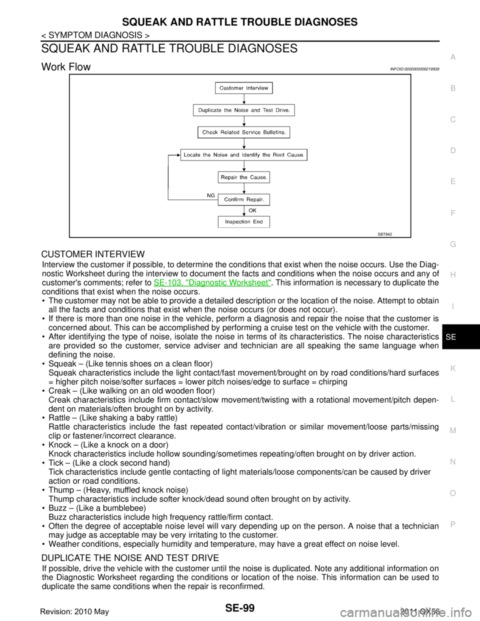
Work FlowINFOID:0000000006219938
CUSTOMER INTERVIEW
Interview the customer if possible, to determine the conditions that exist when the noise occurs. Use the Diag-
nostic Worksheet during the interview to document t he facts and conditions when the noise occurs and any of
customer's comments; refer to SE-103, "
Diagnostic Worksheet". This information is necessary to duplicate the
conditions that exist when the noise occurs.
The customer may not be able to provide a detailed description or the location of the noise. Attempt to obtain all the facts and conditions that exist when the noise occurs (or does not occur).
If there is more than one noise in the vehicle, perform a diagnosis and repair the noise that the customer is
concerned about. This can be accomplished by performing a cruise test on the vehicle with the customer.
After identifying the type of noise, isolate the noise in terms of its characteristics. The noise characteristics
are provided so the customer, service adviser and technician are all speaking the same language when
defining the noise.
Squeak – (Like tennis shoes on a clean floor)
Squeak characteristics include the light contact/fast movement/brought on by road conditions/hard surfaces
= higher pitch noise/softer surfaces = lower pitch noises/edge to surface = chirping
Creak – (Like walking on an old wooden floor)
Creak characteristics include firm contact/slow mo vement/twisting with a rotational movement/pitch depen-
dent on materials/often brought on by activity.
Rattle – (Like shaking a baby rattle)
Rattle characteristics include the fast repeated contac t/vibration or similar movement/loose parts/missing
clip or fastener/incorrect clearance.
Knock – (Like a knock on a door)
Knock characteristics include hollow sounding/someti mes repeating/often brought on by driver action.
Tick – (Like a clock second hand) Tick characteristics include gentle contacting of li ght materials/loose components/can be caused by driver
action or road conditions.
Thump – (Heavy, muffled knock noise) Thump characteristics include softer k nock/dead sound often brought on by activity.
Buzz – (Like a bumblebee)
Buzz characteristics include high frequency rattle/firm contact.
Often the degree of acceptable noise level will vary depending up on the person. A noise that a technician may judge as acceptable may be very irritating to the customer.
Weather conditions, especially humidity and temperat ure, may have a great effect on noise level.
DUPLICATE THE NOISE AND TEST DRIVE
If possible, drive the vehicle with the customer until the noise is duplicated. Note any additional information on
the Diagnostic Worksheet regarding the conditions or lo cation of the noise. This information can be used to
duplicate the same conditions when the repair is reconfirmed.
SBT842
Revision: 2010 May2011 QX56
Page 4607 of 5598
SE-148
< REMOVAL AND INSTALLATION >
CLIMATE CONTROLLED SEAT BLOWER FILTER
CLIMATE CONTROLLED SEAT BLOWER FILTER
SEAT CUSHION
SEAT CUSHION : Removal and InstallationINFOID:0000000006217445
REMOVAL
CAUTION:
When removing and installing, use shop cloths to protect parts from damage.
1. Remove the seat.
2. Turn blower filter counter counterclockwise and remo ve it from climate controlled seat cushion blower
motor.
INSTALLATION
Install in the reverse order of removal.
SEATBACK
SEATBACK : Removal and InstallationINFOID:0000000006217446
REMOVAL
CAUTION:
When removing and installi ng, use shop cloths to protect parts from damage.
1. Remove the seatback board.
2. Turn blower filter counter counterclockwise and re move it from climate controlled seat blower motor.
INSTALLATION
Install in the reverse order of removal.
Revision: 2010 May2011 QX56
Page 4778 of 5598
SPIRAL CABLESR-15
< REMOVAL AND INSTALLATION >
C
DE
F
G
I
J
K L
M A
B
SR
N
O P
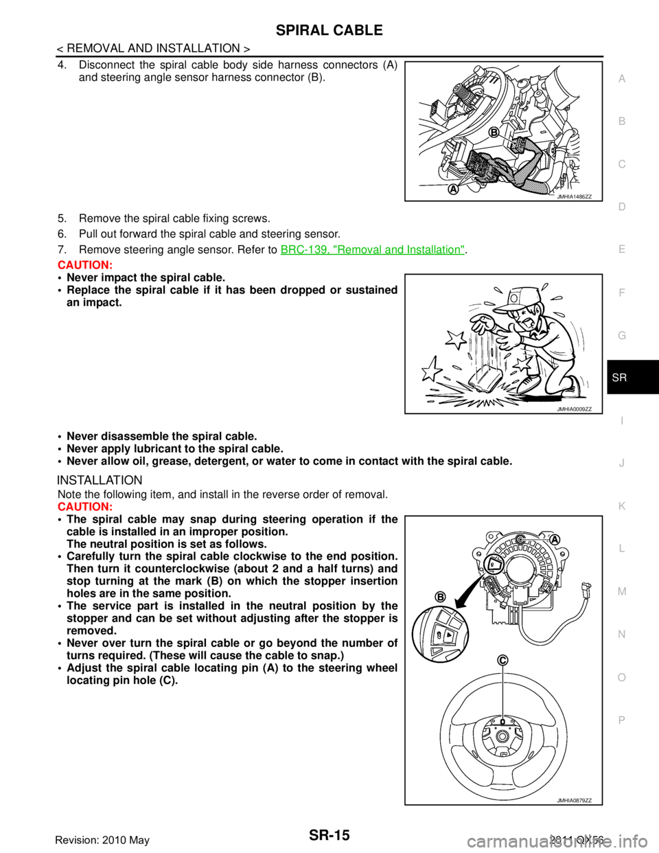
4. Disconnect the spiral cable body side harness connectors (A) and steering angle sensor harness connector (B).
5. Remove the spiral cable fixing screws.
6. Pull out forward the spiral cable and steering sensor.
7. Remove steering angle sensor. Refer to BRC-139, "
Removal and Installation".
CAUTION:
Never impact the spiral cable.
Replace the spiral cable if it has been dropped or sustained
an impact.
Never disassemble the spiral cable.
Never apply lubricant to the spiral cable.
Never allow oil, grease, detergent, or water to come in contact with the spiral cable.
INSTALLATION
Note the following item, and install in the reverse order of removal.
CAUTION:
The spiral cable may snap during steering operation if the
cable is installed in an improper position.
The neutral position is set as follows.
Carefully turn the spiral cable clockwise to the end position.
Then turn it counterclockwise (a bout 2 and a half turns) and
stop turning at the mark (B) on which the stopper insertion
holes are in the same position.
The service part is installed in the neutral position by the
stopper and can be set without adjusting after the stopper is
removed.
Never over turn the spiral cable or go beyond the number of
turns required. (These will cause the cable to snap.)
Adjust the spiral cable locatin g pin (A) to the steering wheel
locating pin hole (C).
JMHIA1486ZZ
JMHIA0009ZZ
JMHIA0879ZZ
Revision: 2010 May2011 QX56
Page 5032 of 5598
STEERING GEAR AND LINKAGEST-45
< REMOVAL AND INSTALLATION >
C
DE
F
H I
J
K L
M A
B
ST
N
O P
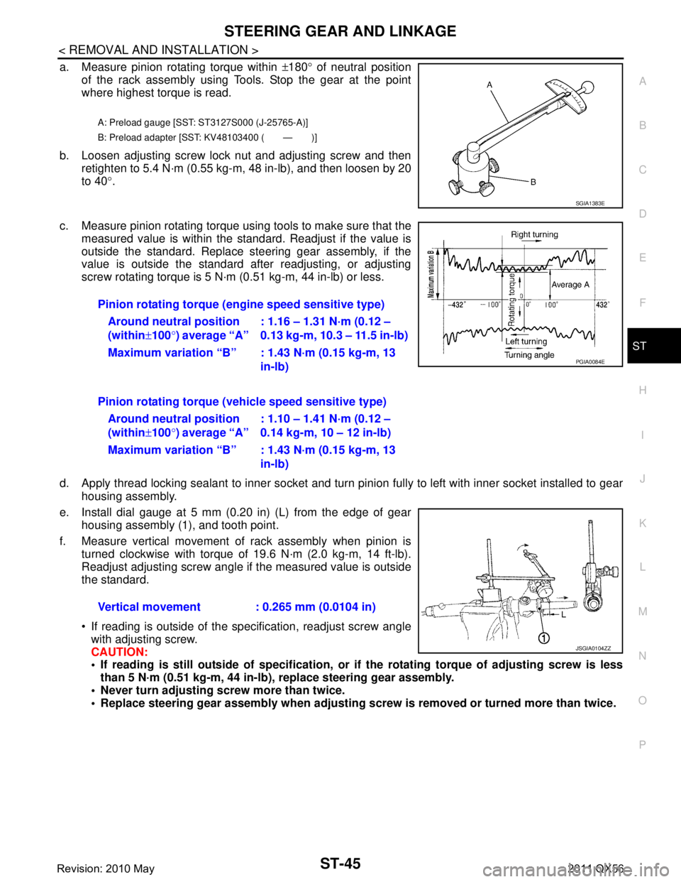
a. Measure pinion rotating torque within ±180 ° of neutral position
of the rack assembly using Tools. Stop the gear at the point
where highest torque is read.
b. Loosen adjusting screw lock nut and adjusting screw and then retighten to 5.4 N·m (0.55 kg-m, 48 in-lb), and then loosen by 20
to 40 °.
c. Measure pinion rotating torque using tools to make sure that the measured value is within the standard. Readjust if the value is
outside the standard. Replace steering gear assembly, if the
value is outside the standard after readjusting, or adjusting
screw rotating torque is 5 N·m (0.51 kg-m, 44 in-lb) or less.
d. Apply thread locking sealant to inner socket and turn pinion fully to left with inner socket installed to gear housing assembly.
e. Install dial gauge at 5 mm (0.20 in) (L) from the edge of gear housing assembly (1), and tooth point.
f. Measure vertical movement of rack assembly when pinion is turned clockwise with torque of 19.6 N·m (2.0 kg-m, 14 ft-lb).
Readjust adjusting screw angle if the measured value is outside
the standard.
If reading is outside of the specification, readjust screw angle
with adjusting screw.
CAUTION:
If reading is still outside of sp ecification, or if the rotating torque of adjusting screw is less
than 5 N·m (0.51 kg-m, 44 in-lb), replace steering gear assembly.
Never turn adjusting scr ew more than twice.
Replace steering gear assembly when adjusting screw is removed or turned more than twice.
A: Preload gauge [SST: ST3127S000 (J-25765-A)]
B: Preload adapter [SST: KV48103400 ( — )]
SGIA1383E
Pinion rotating torque (engine speed sensitive type)
Around neutral position
(within ±100 °) average “A” : 1.16 – 1.31 N·m (0.12 –
0.13 kg-m, 10.3 – 11.5 in-lb)
Maximum variation “B” : 1.43 N·m (0.15 kg-m, 13 in-lb)
Pinion rotating torque (veh icle speed sensitive type)
Around neutral position
(within ±100 °) average “A” : 1.10 – 1.41 N·m (0.12 –
0.14 kg-m, 10 – 12 in-lb)
Maximum variation “B” : 1.43 N·m (0.15 kg-m, 13 in-lb)
Vertical movement : 0.265 mm (0.0104 in)
PGIA0084E
JSGIA0104ZZ
Revision: 2010 May2011 QX56
Page 5111 of 5598
![INFINITI QX56 2011 Factory Service Manual
STRUCTURE AND OPERATIONTM-23
< SYSTEM DESCRIPTION > [7AT: RE7R01B]
C
EF
G H
I
J
K L
M A
B
TM
N
O P
Front planetary gear
Under drive planetary gear
Rear planetary gear
Mid planetary gear
“M1” Posi INFINITI QX56 2011 Factory Service Manual
STRUCTURE AND OPERATIONTM-23
< SYSTEM DESCRIPTION > [7AT: RE7R01B]
C
EF
G H
I
J
K L
M A
B
TM
N
O P
Front planetary gear
Under drive planetary gear
Rear planetary gear
Mid planetary gear
“M1” Posi](/manual-img/42/57033/w960_57033-5110.png)
STRUCTURE AND OPERATIONTM-23
< SYSTEM DESCRIPTION > [7AT: RE7R01B]
C
EF
G H
I
J
K L
M A
B
TM
N
O P
Front planetary gear
Under drive planetary gear
Rear planetary gear
Mid planetary gear
“M1” Position
Name Front sun gear Front carrier Front internal gear
Condition — Output Input
Direction of rotation Counterc lockwise revolution Clockwise revolution Clockwise revolution
Number of revolutions Deceleration from front internal
gear Deceleration from front internal
gear Same number of revolution as the
input shaft
Name Under drive sun gear Under drive carrier Under drive internal gear
Condition — Fixed Input/Output
Direction of rotation Counterclockwi se revolution — Clockwise revolution
Number of revolutions Acceleration from under drive in-
ternal gear —
Same number of revolution as the
front carrier
Name Rear sun gear Rear carrier Rear internal gear
Condition Fixed Output Input
Direction of rotation — Clockwise revolution Clockwise revolution
Number of revolutions — Deceleration from rear internal
gear Same number of revolution as the
under drive internal gear
Name Mid sun gear Mid carrier Mid internal gear
Condition Fixed Output Input
Direction of rotation — Clockwise revolution Clockwise revolution
Number of revolutions — Deceleration from mid internal
gear Same number of revolution as the
rear carrier
Revision: 2010 May2011 QX56
Page 5112 of 5598
![INFINITI QX56 2011 Factory Service Manual
TM-24
< SYSTEM DESCRIPTION >[7AT: RE7R01B]
STRUCTURE AND OPERATION
The 1st one-way clutch and the front brake regulate c
ounterclockwise rotation of the under drive carrier.
NOTE:
The front brake o INFINITI QX56 2011 Factory Service Manual
TM-24
< SYSTEM DESCRIPTION >[7AT: RE7R01B]
STRUCTURE AND OPERATION
The 1st one-way clutch and the front brake regulate c
ounterclockwise rotation of the under drive carrier.
NOTE:
The front brake o](/manual-img/42/57033/w960_57033-5111.png)
TM-24
< SYSTEM DESCRIPTION >[7AT: RE7R01B]
STRUCTURE AND OPERATION
The 1st one-way clutch and the front brake regulate c
ounterclockwise rotation of the under drive carrier.
NOTE:
The front brake operates only while coasting.
The 2nd one-way clutch and the high and low reverse clutch regulate counterclockwise rotation of the rear
sun gear.
NOTE:
The high and low reverse clutch operates only while coasting.
The mid sun gear is fixed by the low brake.
JSDIA0867GB
Revision: 2010 May2011 QX56