2011 INFINITI QX56 display
[x] Cancel search: displayPage 1578 of 5598

DLK-42
< SYSTEM DESCRIPTION >
DIAGNOSIS SYSTEM (BCM)
SELF-DIAG RESULT
Refer to BCS-57, "DTCIndex".
DATA MONITOR
AUTO LOCK SET Auto door lock operation time can be changed in this mode
MODE 1: OFF
MODE 2: 30 sec
MODE 3: 1 minute
MODE 4: 2 minutes
MODE 5: 3 minutes
MODE 6: 4 minutes
MODE 7: 5 minutes
HORN WITH KEYLESS LOCK Horn reminder function mode by Intelligent Key button can be selected from the following with
this mode
On: Operate
Off: Non-operation
PW DOWN SET Unlock button pressing time on Intelligent Key button can be selected from the following with
this mode
MODE 1: 3 sec
MODE 2: Non-operation
MODE 3: 5 sec
WELCOME LIGHT SELECT Welcome light function mode can be selected from the following with this mode
Puddle/Outside Handle
Room lamp
Head & Tail Lamps (this item is displayed, but cannot be used)
Heart Beat
WELCOME LIGHT OP SET Welcome light function mode can be changed to operation with this mode
On: Operate
Off: Non-operation
Monitor item Description
Monitor Item Condition
REQ SW -DR Indicates [On/Off] condition of door request switch (driver side)
REQ SW -AS Indicates [On/Off] condition of door request switch (passenger side)
REQ SW -BD/TR Indicates [On/Off] condition of back door request switch
PUSH SW Indicates [On/Off] condition of push-button ignition switch
CLUTCH SW NOTE:
This item is displayed, but cannot be monitored
BRAKE SW 1 Indicates [On/Off]* condition of stop lamp switch power supply
BRAKE SW 2 Indicates [On/Off] condition of stop lamp switch
DETE/CANCL SW Indicates [On/Off] condition of P position
SFT PN/N SW Indicates [On/Off] condition of P or N position
S/L -LOCK Indicates [On/Off] condition of steering lock unit (LOCK)
S/L -UNLOCK Indicates [On/Off] condition of steering lock unit (UNLOCK)
S/L RELAY -F/B Indicates [On/Off] condition of steering lock relay
UNLK SEN -DR Indicates [On/Off] condition of driver door UNLOCK status
PUSH SW -IPDM Indicates [On/Off] condition of push-button ignition switch
IGN RLY1 -F/B Indicates [On/Off] condition of ignition relay 1
DETE SW -IPDM Indicates [On/Off] condition of P position
SFT PN -IPDM Indicates [On/Off] condition of P or N position
SFT P -MET Indicates [On/Off] condition of P position
SFT N -MET Indicates [On/Off] condition of N position
ENGINE STATE Indicates [Stop/Stall/Crank/Run] condition of engine states
Revision: 2010 May2011 QX56
Page 1579 of 5598

DIAGNOSIS SYSTEM (BCM)DLK-43
< SYSTEM DESCRIPTION >
C
DE
F
G H
I
J
L
M A
B
DLK
N
O P
*: OFF is displayed when brake pedal is depressed while brake switch power supply is OFF.
ACTIVE TEST
S/L LOCK-IPDM Indicates [On/Off] condition of steering lock unit (LOCK)
S/L UNLK-IPDM Indicates [On/Off] condition of steering lock unit (UNLOCK)
S/L RELAY-REQ Indicates [On/Off] condition of steering lock relay
VEH SPEED 1 Display the vehicle speed signal received from combination meter by numerical value [Km/h]
VEH SPEED 2 Display the vehicle spee d signal received from ABS or VDC or TCM by numerical value [Km/h]
DOOR STAT-DR Indicates [LOCK/READY/UNLK] condition of unlock sensor
DOOR STAT-AS Indicates [LOCK/READY/UNLK] condition of passenger side door status
ID OK FLAG Indicates [Set/Reset] condition of key ID
PRMT ENG STRT Indicates [Set/Reset] condition of engine start possibility
PRMT RKE STRT NOTE:
This item is displayed, but cannot be monitored
TRNK/HAT MNTR NOTE:
This item is displayed, but cannot be monitored
RKE-LOCK Indicates [On/Off] condition of LOCK signal from Intelligent Key
RKE-UNLOCK Indicates [On/Off] condition of UNLOCK signal from Intelligent Key
RKE-TR/BD NOTE:
This item is displayed, but cannot be monitored
RKE-PANIC Indicates [On/Off] condition of PANIC button of Intelligent Key
RKE-MODE CHG Indicates [On/Off] condition of MODE CHANGE signal from Intelligent Key
RKE OPE COUN1 When remote keyless entry receiver receives the signal transmitted while operating on Intelli-
gent Key, the numerical value start changing
RKE OPE COUN2 NOTE:
This item is displayed, but cannot be monitored
Monitor Item Condition
Test item Description
BATTERY SAVER This test is able to check interior room lamp operation
On: Operate
Off: Non-operation
OUTSIDE BUZZER This test is able to check Intelligent Key warning buzzer operation
On: Operate
Off: Non-operation
INSIDE BUZZER This test is able to check warning chime in combination meter operation
Take Out: Take away warning chime sounds when CONSULT-III screen is touched
Key: Key warning chime sounds when CONSULT-III screen is touched
Knob: OFF position warning chime sounds when CONSULT-III screen is touched
Off: Non-operation
INDICATOR This test is able to check warning lamp operation
KEY ON: “KEY” Warning lamp illuminates when CONSULT-III screen is touched
KEY IND: “KEY” Warning lamp blinks when CONSULT-III screen is touched
Off: Non-operation
INT LAMP This test is able to check interior room lamp operation
On: Operate
Off: Non-operation
Revision: 2010 May2011 QX56
Page 1580 of 5598

DLK-44
< SYSTEM DESCRIPTION >
DIAGNOSIS SYSTEM (BCM)
TRUNK
TRUNK : CONSULT-III Function (BCM - TRUNK)INFOID:0000000006225857
DATA MONITOR
LCD This test is able to check meter display information
Engine start information displays when “BP N” on CONSULT-III screen is touched
Engine start information displays when “BP I” on CONSULT-III screen is touched
Key ID warning displays when “ID NG” on CONSULT-III screen is touched
Steering lock information displays when “ROTAT” on CONSULT-III screen is touched
P position warning displays when “SFT P” on CONSULT-III screen is touched
INSRT: This item is displayed, but cannot be monitored
BATT: This item is displayed, but cannot be monitored
Take away through window warning displays
when “NO KY” on CONSULT-III screen is
touched
Take away warning display when “OUTKEY” on CONSULT-III screen is touched
OFF position warning display when “LK WN” on CONSULT-III screen is touched
FLASHER This test is able to check security hazard lamp operation
The hazard lamps are activated after “LH/RH/Off” on CONSULT-III screen is touched
P RANGE This test is able to check A/T shift selector power supply
On: Operate
Off: Non-operation
ENGINE SW ILLUMI This test is able to check push-button ignition switch illumination operation
Push-ignition switch illumination illuminates when “ON” on CONSULT-III screen is touched
LOCK INDICATOR This test is able to check LOCK indicato
r (push-button ignition switch) operation
On: Operate
Off: Non-operation
ACC INDICATOR This test is able to check ACC indicator (push-button ignition switch) operation
On: Operate
Off: Non-operation
IGNITION ON IND This test is able to check ON indicator (push-button ignition switch) operation
On: Operate
Off: Non-operation
HORN This test is able to check horn operation
On: Operate
Off: Non-operation
TRUNK/BACK DOOR NOTE:
This item is displayed, but cannot be used
Test item Description
Monitor Item Contents
PUSH SW Indicates [On/Off] condition of push switch
UNLK SEN -DR Indicates [On/Off] condition of unlock sensor
VEH SPEED 1 Indicates [Km/h] condition of ve hicle speed signal from combination meter
TR/BD OPEN SW Indicates [On/Off] condition of back door opener switch
TRNK/HAT MNTR NOTE:
This item is displayed, but cannot be monitored
RKE-TR/BD NOTE:
This item is displayed, but cannot be monitored
Revision: 2010 May2011 QX56
Page 1581 of 5598

DIAGNOSIS SYSTEM (AUTOMATIC BACK DOOR CONTROL UNIT)
DLK-45
< SYSTEM DESCRIPTION >
C
D E
F
G H
I
J
L
M A
B
DLK
N
O P
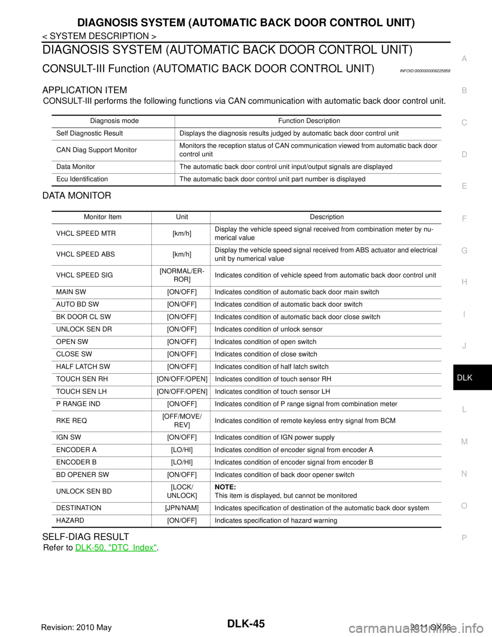
DIAGNOSIS SYSTEM (AUTOMATIC BACK DOOR CONTROL UNIT)
CONSULT-III Function (AUTOMATIC BACK DOOR CONTROL UNIT)INFOID:0000000006225858
APPLICATION ITEM
CONSULT-III performs the following functions via CA N communication with automatic back door control unit.
DATA MONITOR
SELF-DIAG RESULT
Refer to DLK-50, "DTCIndex".
Diagnosis mode Function Description
Self Diagnostic Result Displays the diagnosis results judged by automatic back door control unit
CAN Diag Support Monitor Monitors the reception status of CAN communication viewed from automatic back door
control unit
Data Monitor The automatic back door control unit input/output signals are displayed
Ecu Identification The automatic back door control unit part number is displayed
Monitor Item Unit Description
VHCL SPEED MTR [km/h] Display the vehicle speed signal received from combination meter by nu-
merical value
VHCL SPEED ABS [km/h] Display the vehicle speed
signal received from ABS actuator and electrical
unit by numerical value
VHCL SPEED SIG [NORMAL/ER-
ROR] Indicates condition of vehicle speed from automatic back door control unit
MAIN SW [ON/OFF] Indicates condition of automatic back door main switch
AUTO BD SW [ON/OFF] Indicates condition of automatic back door switch
BK DOOR CL SW [ON/OFF] Indicates condition of automatic back door close switch
UNLOCK SEN DR [ON/OFF] Indicates condition of unlock sensor
OPEN SW [ON/OFF] Indicates condition of open switch
CLOSE SW [ON/OFF] Indicates condition of close switch
HALF LATCH SW [ON/OFF] Indicates condition of half latch switch
TOUCH SEN RH [ON/OFF/OPEN] Indicates condition of touch sensor RH
TOUCH SEN LH [ON/OFF/OPEN] Indicates condition of touch sensor LH
P RANGE IND [ON/OFF] Indicates condition of P range signal from combination meter
RKE REQ [OFF/MOVE/
REV] Indicates condition of remote keyless entry signal from BCM
IGN SW [ON/OFF] Indicates condition of IGN power supply
ENCODER A [LO/HI] Indicates condition of encoder signal from encoder A
ENCODER B [LO/HI] Indicates condition of encoder signal from encoder B
BD OPENER SW [ON/OFF] Indicates condition of back door opener switch
UNLOCK SEN BD [LOCK/
UNLOCK] NOTE:
This item is displayed, but cannot be monitored
DESTINATION [JPN/NAM] Indicates specification of destination of the automatic back door system
HAZARD [ON/OFF] Indica tes specification of hazard warning
Revision: 2010 May2011 QX56
Page 1585 of 5598

AUTOMATIC BACK DOOR CONTROL MODULEDLK-49
< ECU DIAGNOSIS INFORMATION >
C
DE
F
G H
I
J
L
M A
B
DLK
N
O P
Fail SafeINFOID:0000000006225861
DTC Inspection Priority ChartINFOID:0000000006225862
If some DTCs are displayed at the same time, per form inspections one by one based on the following priority
chart.
16
(LG) Ground
Touch sensor RH sig-
nal Input Touch sensor RH Detect obstruc-
tion
0 V
Other than above 6 V
17
(O) Ground Automatic back door
main switch
InputAutomatic back
door main switch ON Battery voltage
OFF 0 V
19
(L/Y) Ground Close switch signal Input Back door Fully closed 0 V
Open/half latch Battery voltage
20
(G/Y) Ground Open switch signal Input Back door Open 0 V
Half latch/fully
closed
Battery voltage
22
(B) Ground Ground (destination) — — 0 V
23
(B) Ground
Ground (Hazard re-
minder) —— 0 V
28
(R/W) Ground Power supply (BAT) Input — Battery voltage
34
(B) Ground Ground — — 0 V
Te r m i n a l N o .
(Wire color) Description
Condition Vo l ta g e
(Approx.)
(+) (–) Signal name Input/
Output
Display contents of CONSUL T-III Fail-safe Cancellation
B2401 IGN OPEN Intermittent clutch function All following condition are satisfied
Power supply condition of auto-
matic back door control unit: OFF
BCM receive ignition position sig- nal (OFF) via CAN
B2403 PULSE ENCODER Inhibit automatic back door operation When receiving the pulse from en-
coders A and B normally (5 pulses)
B2409 HALF LATCH SW Intermittent clutch function Half latch switch is ON from OFF
B2416 TOUCH SEN R OPEN During close operation: Intermittent clutch
function
Normal return
B2417 TOUCH SEN L OPEN During close operation: Intermittent clutch
function Normal return
B2419 OPEN SW Inhibit automatic back door operation Erase DTC, reconnect battery
B2420 CLOSE SW Inhibit automatic back door operation Erase DTC, reconnect battery
B2421 CLUTCH TIME OUT Intermittent clutch function Reception of next operation request
B2422 BACK DOOR STATE Intermittent clutch function Detect back door fully closed posi-
tion
B2423 ABD MTR TIME OUT Intermittent clutch function Reception of next operation request
B2424 CLSR CONDITION Inhibit automatic back door operation Normal return or reconnect battery
Revision: 2010 May2011 QX56
Page 1586 of 5598

DLK-50
< ECU DIAGNOSIS INFORMATION >
AUTOMATIC BACK DOOR CONTROL MODULE
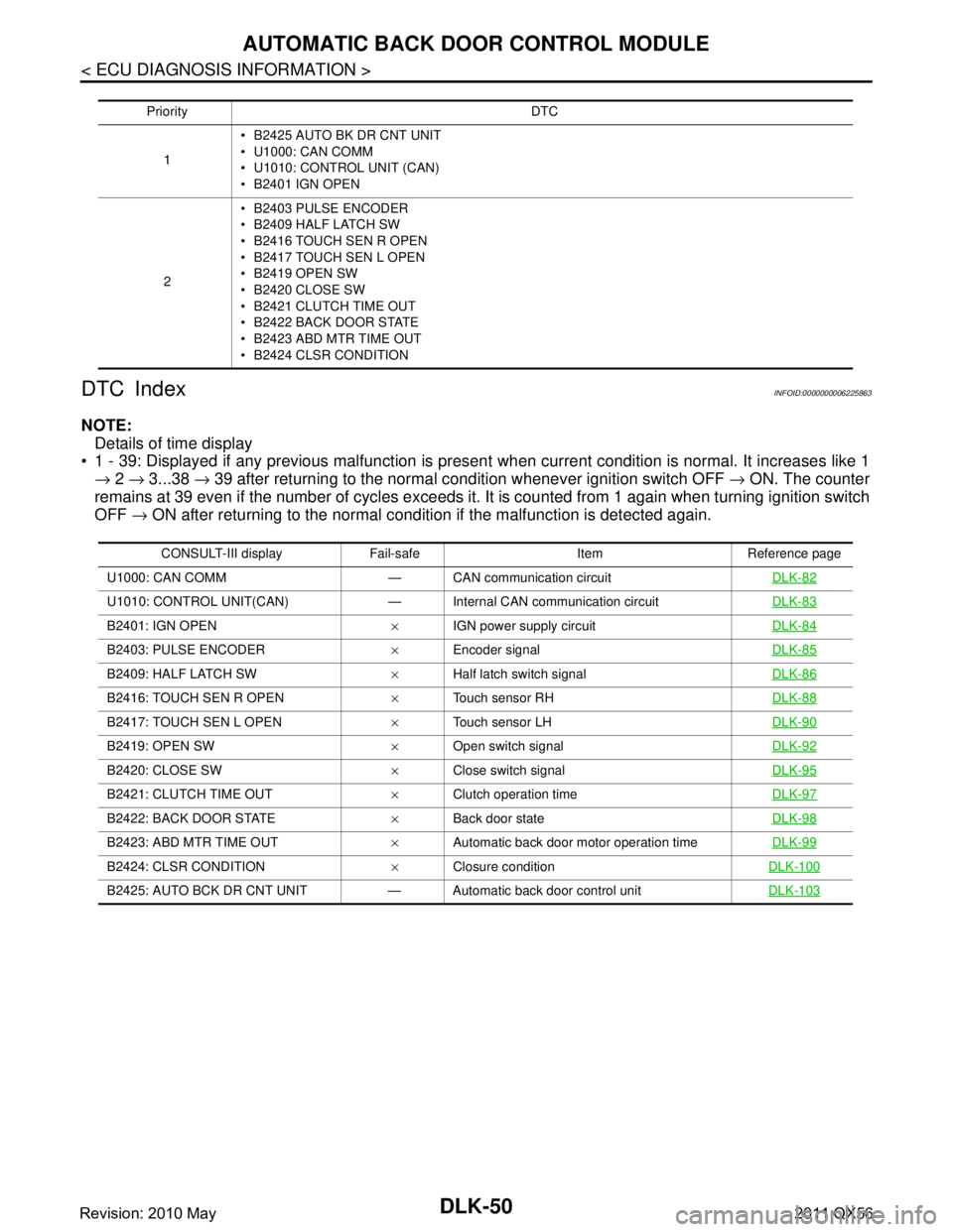
DTC Index
INFOID:0000000006225863
NOTE: Details of time display
1 - 39: Displayed if any previous malfunction is present when current condition is normal. It increases like 1
→ 2 → 3...38 → 39 after returning to the normal condition whenever ignition switch OFF → ON. The counter
remains at 39 even if the number of cycles exceeds it . It is counted from 1 again when turning ignition switch
OFF → ON after returning to the normal condition if the malfunction is detected again.
Priority DTC
1 B2425 AUTO BK DR CNT UNIT
U1000: CAN COMM
U1010: CONTROL UNIT (CAN)
B2401 IGN OPEN
2 B2403 PULSE ENCODER
B2409 HALF LATCH SW
B2416 TOUCH SEN R OPEN
B2417 TOUCH SEN L OPEN
B2419 OPEN SW
B2420 CLOSE SW
B2421 CLUTCH TIME OUT
B2422 BACK DOOR STATE
B2423 ABD MTR TIME OUT
B2424 CLSR CONDITION
CONSULT-III display Fail-safe Item Reference page
U1000: CAN COMM — CAN communication circuit DLK-82
U1010: CONTROL UNIT(CAN) — Internal CAN communication circuitDLK-83
B2401: IGN OPEN×IGN power supply circuit DLK-84
B2403: PULSE ENCODER×Encoder signal DLK-85
B2409: HALF LATCH SW×Half latch switch signal DLK-86
B2416: TOUCH SEN R OPEN×Touch sensor RH DLK-88
B2417: TOUCH SEN L OPEN×Touch sensor LH DLK-90
B2419: OPEN SW×Open switch signal DLK-92
B2420: CLOSE SW×Close switch signal DLK-95
B2421: CLUTCH TIME OUT×Clutch operation time DLK-97
B2422: BACK DOOR STATE×Back door state DLK-98
B2423: ABD MTR TIME OUT×Automatic back door motor operation time DLK-99
B2424: CLSR CONDITION×Closure condition DLK-100
B2425: AUTO BCK DR CNT UNIT — Automatic back door control unit DLK-103
Revision: 2010 May2011 QX56
Page 1614 of 5598

DLK-78
< BASIC INSPECTION >
DIAGNOSIS AND REPAIR WORK FLOW
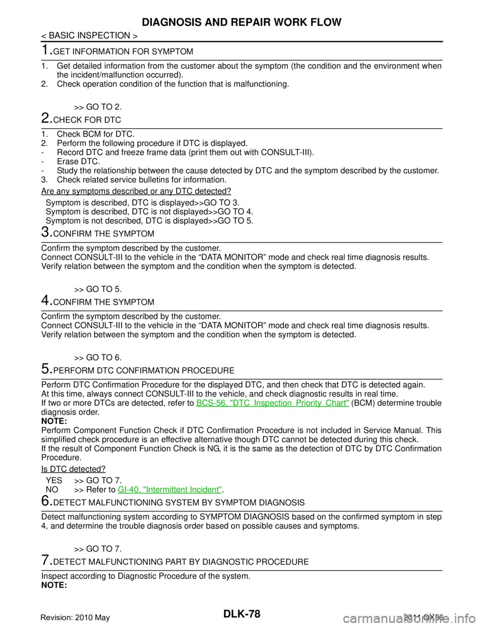
1.GET INFORMATION FOR SYMPTOM
1. Get detailed information from the customer about the symptom (the condition and the environment when
the incident/malfunction occurred).
2. Check operation condition of the function that is malfunctioning.
>> GO TO 2.
2.CHECK FOR DTC
1. Check BCM for DTC.
2. Perform the following procedure if DTC is displayed.
- Record DTC and freeze frame data (print them out with CONSULT-III).
- Erase DTC.
- Study the relationship between the cause detected by DTC and the symptom described by the customer.
3. Check related service bulletins for information.
Are any symptoms described or any DTC detected?
Symptom is described, DTC is displayed>>GO TO 3.
Symptom is described, DTC is not displayed>>GO TO 4.
Symptom is not described, DTC is displayed>>GO TO 5.
3.CONFIRM THE SYMPTOM
Confirm the symptom described by the customer.
Connect CONSULT-III to the vehicle in the “DATA MO NITOR” mode and check real time diagnosis results.
Verify relation between the symptom and the condition when the symptom is detected.
>> GO TO 5.
4.CONFIRM THE SYMPTOM
Confirm the symptom described by the customer.
Connect CONSULT-III to the vehicle in the “DATA MO NITOR” mode and check real time diagnosis results.
Verify relation between the symptom and the condition when the symptom is detected.
>> GO TO 6.
5.PERFORM DTC CONFIRMATION PROCEDURE
Perform DTC Confirmation Procedure for the display ed DTC, and then check that DTC is detected again.
At this time, always connect CONSULT-III to the vehicle, and check diagnostic results in real time.
If two or more DTCs are detected, refer to BCS-56, "
DTCInspectionPriorityChart" (BCM) determine trouble
diagnosis order.
NOTE:
Perform Component Function Check if DTC Confirmati on Procedure is not included in Service Manual. This
simplified check procedure is an effective alternat ive though DTC cannot be detected during this check.
If the result of Component Function Check is NG, it is the same as the detection of DTC by DTC Confirmation
Procedure.
Is DTC detected?
YES >> GO TO 7.
NO >> Refer to GI-40, "
Intermittent Incident".
6.DETECT MALFUNCTIONING SYSTEM BY SYMPTOM DIAGNOSIS
Detect malfunctioning system according to SYMPTOM DIAGNOSIS based on the confirmed symptom in step
4, and determine the trouble diagnosis order based on possible causes and symptoms.
>> GO TO 7.
7.DETECT MALFUNCTIONING PART BY DIAGNOSTIC PROCEDURE
Inspect according to Diagnostic Procedure of the system.
NOTE:
Revision: 2010 May2011 QX56
Page 1615 of 5598

DIAGNOSIS AND REPAIR WORK FLOWDLK-79
< BASIC INSPECTION >
C
DE
F
G H
I
J
L
M A
B
DLK
N
O P
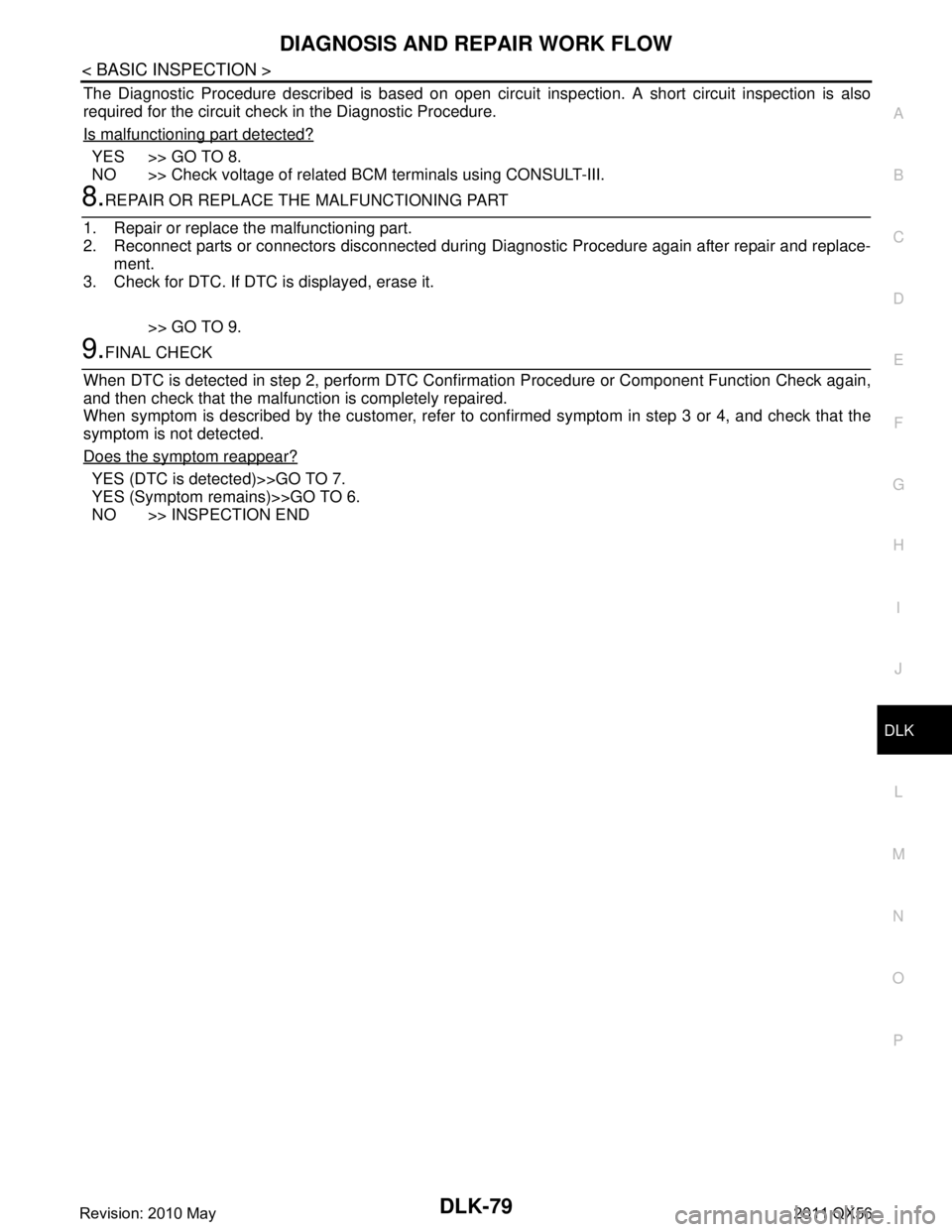
The Diagnostic Procedure described is based on open circuit inspection. A short circuit inspection is also
required for the circuit check in the Diagnostic Procedure.
Is malfunctioning part detected?
YES >> GO TO 8.
NO >> Check voltage of related BCM terminals using CONSULT-III.
8.REPAIR OR REPLACE THE MALFUNCTIONING PART
1. Repair or replace the malfunctioning part.
2. Reconnect parts or connectors disconnected during Diagnostic Procedure again after repair and replace-
ment.
3. Check for DTC. If DTC is displayed, erase it.
>> GO TO 9.
9.FINAL CHECK
When DTC is detected in step 2, perform DTC Conf irmation Procedure or Component Function Check again,
and then check that the malfunction is completely repaired.
When symptom is described by the customer, refer to c onfirmed symptom in step 3 or 4, and check that the
symptom is not detected.
Does the symptom reappear?
YES (DTC is detected)>>GO TO 7.
YES (Symptom remains)>>GO TO 6.
NO >> INSPECTION END
Revision: 2010 May2011 QX56