2011 INFINITI QX56 display
[x] Cancel search: displayPage 1650 of 5598
DLK-114
< DTC/CIRCUIT DIAGNOSIS >
B2628 OUTSIDE ANTENNA
B2628 OUTSIDE ANTENNA
DTC LogicINFOID:0000000006225918
DTC DETECTION LOGIC
DTC CONFIRMATION PROCEDURE
1.PERFORM DTC CONFIRMATION PROCEDURE
1. Turn ignition switch ON.
2. Check “Self Diagnostic Result” m ode of “BCM” using CONSULT-III.
Is DTC detected?
YES >> Refer to DLK-108, "Diagnosis Procedure".
NO >> Outside key antenna (back door) is OK.
Diagnosis ProcedureINFOID:0000000006225919
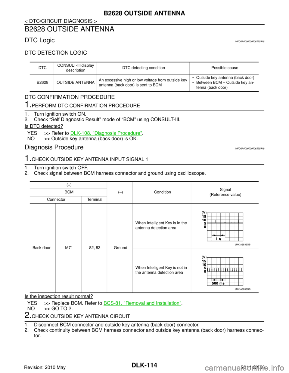
1.CHECK OUTSIDE KEY ANTENNA INPUT SIGNAL 1
1. Turn ignition switch OFF.
2. Check signal between BCM harness connector and ground using oscilloscope.
Is the inspection result normal?
YES >> Replace BCM. Refer to BCS-81, "Removal and Installation".
NO >> GO TO 2.
2.CHECK OUTSIDE KEY ANTENNA CIRCUIT
1. Disconnect BCM connector and outside key antenna (back door) connector.
2. Check continuity between BCM harness connector and outside key antenna (back door) harness connec- tor.
DTC CONSULT-III display
description DTC detecting condition Possible cause
B2628 OUTSIDE ANTENNA An excessive high or low voltage from outside key
antenna (back door) is sent to BCM Outside key antenna (back door)
Between BCM – Outside key an-
tenna (back door)
(+)
(–) Condition Signal
(Reference value)
BCM
Connector Terminal
Back door M71 82, 83 Ground When Intelligent Key is in the
antenna detection area
When Intelligent Key is not in
the antenna detection area
JMKIA3839GB
JMKIA3838GB
Revision: 2010 May2011 QX56
Page 1683 of 5598
INFORMATION DISPLAYDLK-147
< DTC/CIRCUIT DIAGNOSIS >
C
DE
F
G H
I
J
L
M A
B
DLK
N
O P
INFORMATION DISPLAY
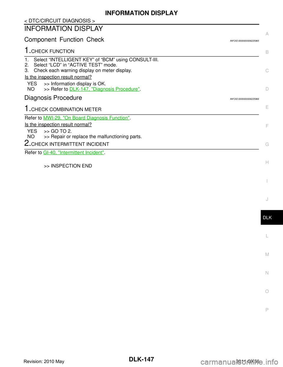
Component Function CheckINFOID:0000000006225965
1.CHECK FUNCTION
1. Select “INTELLIGENT KEY” of “BCM” using CONSULT-III.
2. Select “LCD” in “ACTIVE TEST” mode.
3. Check each warning display on meter display.
Is the inspection result normal?
YES >> Information display is OK.
NO >> Refer to DLK-147, "
Diagnosis Procedure".
Diagnosis ProcedureINFOID:0000000006225966
1.CHECK COMBINATION METER
Refer to MWI-29, "
On Board Diagnosis Function".
Is the inspection result normal?
YES >> GO TO 2.
NO >> Repair or replace the malfunctioning parts.
2.CHECK INTERMITTENT INCIDENT
Refer to GI-40, "
Intermittent Incident".
>> INSPECTION END
Revision: 2010 May2011 QX56
Page 1725 of 5598
P POSITION WARNING DOES NOT OPERATEDLK-189
< SYMPTOM DIAGNOSIS >
C
DE
F
G H
I
J
L
M A
B
DLK
N
O P
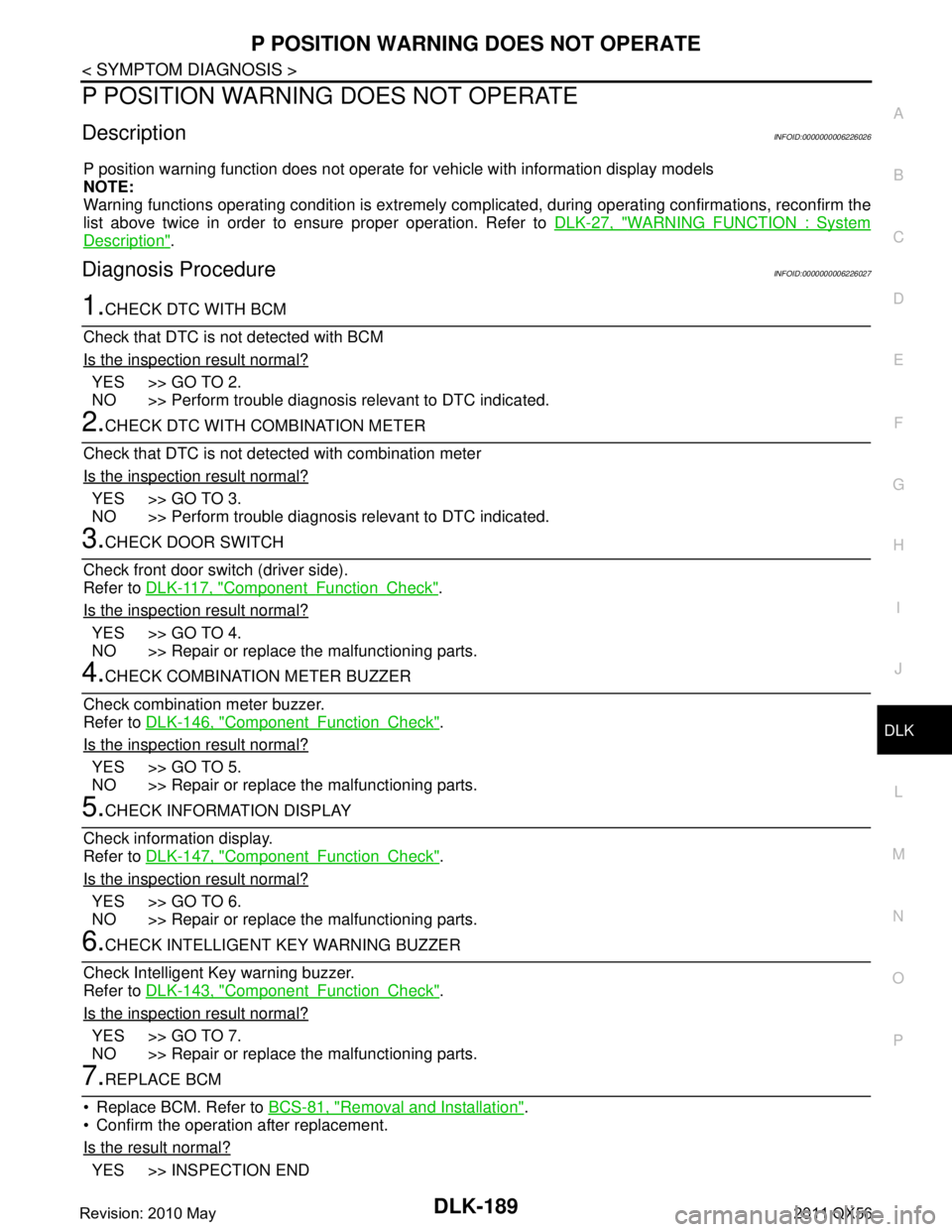
P POSITION WARNING DOES NOT OPERATE
DescriptionINFOID:0000000006226026
P position warning function does not operate fo r vehicle with information display models
NOTE:
Warning functions operating condition is extremely comp licated, during operating confirmations, reconfirm the
list above twice in order to ensure proper operation. Refer to DLK-27, "
WARNING FUNCTION : System
Description".
Diagnosis ProcedureINFOID:0000000006226027
1.CHECK DTC WITH BCM
Check that DTC is not detected with BCM
Is the inspection result normal?
YES >> GO TO 2.
NO >> Perform trouble diagnosis relevant to DTC indicated.
2.CHECK DTC WITH COMBINATION METER
Check that DTC is not detected with combination meter
Is the inspection result normal?
YES >> GO TO 3.
NO >> Perform trouble diagnosis relevant to DTC indicated.
3.CHECK DOOR SWITCH
Check front door switch (driver side).
Refer to DLK-117, "
ComponentFunctionCheck".
Is the inspection result normal?
YES >> GO TO 4.
NO >> Repair or replace the malfunctioning parts.
4.CHECK COMBINATION METER BUZZER
Check combination meter buzzer.
Refer to DLK-146, "
ComponentFunctionCheck".
Is the inspection result normal?
YES >> GO TO 5.
NO >> Repair or replace the malfunctioning parts.
5.CHECK INFORMATION DISPLAY
Check information display.
Refer to DLK-147, "
ComponentFunctionCheck".
Is the inspection result normal?
YES >> GO TO 6.
NO >> Repair or replace the malfunctioning parts.
6.CHECK INTELLIGENT KEY WARNING BUZZER
Check Intelligent Key warning buzzer.
Refer to DLK-143, "
ComponentFunctionCheck".
Is the inspection result normal?
YES >> GO TO 7.
NO >> Repair or replace the malfunctioning parts.
7.REPLACE BCM
Replace BCM. Refer to BCS-81, "
Removal and Installation".
Confirm the operation after replacement.
Is the result normal?
YES >> INSPECTION END
Revision: 2010 May2011 QX56
Page 1727 of 5598

ACC WARNING DOES NOT OPERATEDLK-191
< SYMPTOM DIAGNOSIS >
C
DE
F
G H
I
J
L
M A
B
DLK
N
O P
ACC WARNING DOES NOT OPERATE
DescriptionINFOID:0000000006226028
ACC warning function does not operate for vehicle with information display models
NOTE:
Warning functions operating condition is extremely comp licated, during operating confirmations, reconfirm the
list above twice in order to ensure proper operation. Refer to DLK-27, "
WARNING FUNCTION : System
Description".
Diagnosis ProcedureINFOID:0000000006226029
1.CHECK DTC WITH BCM
Check that DTC is not detected with BCM
Is the inspection result normal?
YES >> GO TO 2.
NO >> Perform trouble diagnosis relevant to DTC indicated.
2.CHECK DTC WITH COMBINATION METER
Check that DTC is not detected with combination meter
Is the inspection result normal?
YES >> GO TO 3.
NO >> Perform trouble diagnosis relevant to DTC indicated.
3.CHECK COMBINATION METER BUZZER
Check combination meter buzzer.
Refer to DLK-146, "
ComponentFunctionCheck".
Is the inspection result normal?
YES >> GO TO 4.
NO >> Repair or replace the malfunctioning parts.
4.CHECK INFORMATION DISPLAY
Check information display.
Refer to DLK-147, "
ComponentFunctionCheck".
Is the inspection result normal?
YES >> GO TO 5.
NO >> Repair or replace the malfunctioning parts.
5.REPLACE BCM
Replace BCM. Refer to BCS-81, "
Removal and Installation".
Confirm the operation after replacement.
Is the result normal?
YES >> INSPECTION END
NO >> Check intermittent incident. Refer to GI-40, "
Intermittent Incident".
Revision: 2010 May2011 QX56
Page 1728 of 5598
DLK-192
< SYMPTOM DIAGNOSIS >
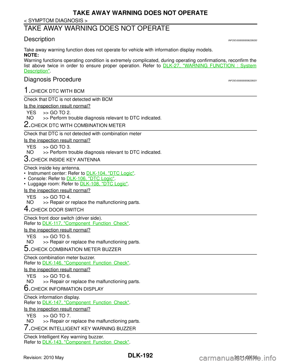
TAKE AWAY WARNING DOES NOT OPERATE
TAKE AWAY WARNING DOES NOT OPERATE
DescriptionINFOID:0000000006226030
Take away warning function does not operate for vehicle with information display models.
NOTE:
Warning functions operating condition is extremely complicated, during operating confirmations, reconfirm the
list above twice in order to ensure proper operation. Refer to DLK-27, "
WARNING FUNCTION : System
Description".
Diagnosis ProcedureINFOID:0000000006226031
1.CHECK DTC WITH BCM
Check that DTC is not detected with BCM
Is the inspection result normal?
YES >> GO TO 2.
NO >> Perform trouble diagnosis relevant to DTC indicated.
2.CHECK DTC WITH COMBINATION METER
Check that DTC is not detected with combination meter
Is the inspection result normal?
YES >> GO TO 3.
NO >> Perform trouble diagnosis relevant to DTC indicated.
3.CHECK INSIDE KEY ANTENNA
Check inside key antenna.
Instrument center: Refer to DLK-104, "
DTC Logic".
Console: Refer to DLK-106, "
DTC Logic".
Luggage room: Refer to DLK-108, "
DTC Logic".
Is the inspection result normal?
YES >> GO TO 4.
NO >> Repair or replace the malfunctioning parts.
4.CHECK DOOR SWITCH
Check front door switch (driver side).
Refer to DLK-117, "
ComponentFunctionCheck".
Is the inspection result normal?
YES >> GO TO 5.
NO >> Repair or replace the malfunctioning parts.
5.CHECK COMBINATION METER BUZZER
Check combination meter buzzer.
Refer to DLK-146, "
ComponentFunctionCheck".
Is the inspection result normal?
YES >> GO TO 6.
NO >> Repair or replace the malfunctioning parts.
6.CHECK INFORMATION DISPLAY
Check information display.
Refer to DLK-147, "
ComponentFunctionCheck".
Is the inspection result normal?
YES >> GO TO 7.
NO >> Repair or replace the malfunctioning parts.
7.CHECK INTELLIGENT KEY WARNING BUZZER
Check Intelligent Key warning buzzer.
Refer to DLK-143, "
ComponentFunctionCheck".
Revision: 2010 May2011 QX56
Page 1730 of 5598

DLK-194
< SYMPTOM DIAGNOSIS >
KEY ID WARNING DOES NOT OPERATE
KEY ID WARNING DOES NOT OPERATE
DescriptionINFOID:0000000006226032
Key ID warning function does not operate for vehicle with information display models.
NOTE:
Warning functions operating condition is extremely comp licated, during operating confirmations, reconfirm the
list above twice in order to ensure proper operation. Refer to DLK-27, "
WARNING FUNCTION : System
Description".
Diagnosis ProcedureINFOID:0000000006226033
1.CHECK DTC WITH BCM
Check that DTC is not detected with BCM
Is the inspection result normal?
YES >> GO TO 2.
NO >> Perform trouble diagnosis relevant to DTC indicated.
2.CHECK DTC WITH COMBINATION METER
Check that DTC is not detected with combination meter
Is the inspection result normal?
YES >> GO TO 3.
NO >> Perform trouble diagnosis relevant to DTC indicated.
3.CHECK INTELLIGENT KEY
Check Intelligent Key.
Refer to DLK-145, "
ComponentFunctionCheck".
Is the inspection result normal?
YES >> GO TO 4.
NO >> Repair or replace the malfunctioning parts.
4.CHECK INSIDE KEY ANTENNA
Check inside key antenna.
Instrument center: Refer to DLK-104, "
DTC Logic".
Console: Refer to DLK-106, "
DTC Logic".
Luggage room: Refer to DLK-108, "
DTC Logic".
Is the inspection result normal?
YES >> GO TO 5.
NO >> Repair or replace the malfunctioning parts.
5.CHECK INFORMATION DISPLAY
Check information display.
Refer to DLK-147, "
ComponentFunctionCheck".
Is the inspection result normal?
YES >> GO TO 6.
NO >> Repair or replace the malfunctioning parts.
6.REPLACE BCM
Replace BCM. Refer to BCS-81, "
Removal and Installation".
Confirm the operation after replacement.
Is the result normal?
YES >> INSPECTION END
NO >> Check intermittent incident. Refer to GI-40, "
Intermittent Incident".
Revision: 2010 May2011 QX56
Page 1731 of 5598
INTELLIGENT KEY LOW BATTERY WARNING DOES NOT OPERATE
DLK-195
< SYMPTOM DIAGNOSIS >
C
D E
F
G H
I
J
L
M A
B
DLK
N
O P
INTELLIGENT KEY LOW BATTERY WARNING DOES NOT OPERATE
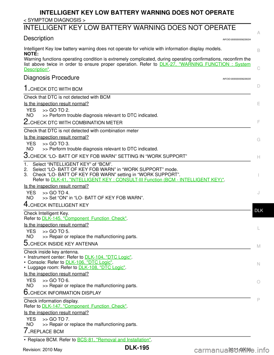
DescriptionINFOID:0000000006226034
Intelligent Key low battery warning does not operat e for vehicle with information display models.
NOTE:
Warning functions operating condition is extremely comp licated, during operating confirmations, reconfirm the
list above twice in order to ensure proper operation. Refer to DLK-27, "
WARNING FUNCTION : System
Description".
Diagnosis ProcedureINFOID:0000000006226035
1.CHECK DTC WITH BCM
Check that DTC is not detected with BCM
Is the inspection result normal?
YES >> GO TO 2.
NO >> Perform trouble diagnosis relevant to DTC indicated.
2.CHECK DTC WITH COMBINATION METER
Check that DTC is not detected with combination meter
Is the inspection result normal?
YES >> GO TO 3.
NO >> Perform trouble diagnosis relevant to DTC indicated.
3.CHECK “LO- BATT OF KEY FOB WARN” SETTING IN “WORK SUPPORT”
1. Select “INTELLIGENT KEY” of “BCM”.
2. Select “LO- BATT OF KEY FOB WARN” in “WORK SUPPORT” mode.
3. Check “LO- BATT OF KEY FOB WARN” setting in “WORK SUPPORT”. Refer to DLK-41, "
INTELLIGENT KEY : CONSULT-III Function (BCM - INTELLIGENT KEY)".
Is the inspection result normal?
YES >> GO TO 4.
NO >> Set “ON” in “LO- BATT OF KEY FOB WARN”.
4.CHECK INTELLIGENT KEY
Check Intelligent Key.
Refer to DLK-145, "
ComponentFunctionCheck".
Is the inspection result normal?
YES >> GO TO 5.
NO >> Repair or replace the malfunctioning parts.
5.CHECK INSIDE KEY ANTENNA
Check inside key antenna.
Instrument center: Refer to DLK-104, "
DTC Logic".
Console: Refer to DLK-106, "
DTC Logic".
Luggage room: Refer to DLK-108, "
DTC Logic".
Is the inspection result normal?
YES >> GO TO 6.
NO >> Repair or replace the malfunctioning parts.
6.CHECK INFORMATION DISPLAY
Check information display.
Refer to DLK-147, "
ComponentFunctionCheck".
Is the inspection result normal?
YES >> GO TO 7.
NO >> Repair or replace the malfunctioning parts.
7.REPLACE BCM
Replace BCM. Refer to BCS-81, "
Removal and Installation".
Revision: 2010 May2011 QX56
Page 1805 of 5598
DLN-3
CEF
G H
I
J
K L
M A
B
DLN
N
O P
U1000 CAN COMM CIRCUIT ......................... ....91
Description .......................................................... ....91
DTC Logic ...............................................................91
Diagnosis Procedure ...............................................91
U1010 CONTROL UNIT (CAN) ..........................92
Description .......................................................... ....92
DTC Logic ...............................................................92
Diagnosis Procedure ...............................................92
POWER SUPPLY AND GROUND CIRCUIT ......93
Description .......................................................... ....93
Diagnosis Procedure ...............................................93
4WD WARNING LAMP ......................................97
Component Function Check ................................ ....97
Diagnosis Procedure ...............................................97
4WD INDICATOR LAMP ....................................98
Component Function Check ................................ ....98
Diagnosis Procedure ...............................................98
SYMPTOM DIAGNOSIS ..............................99
HEAVY TIGHT-CORNER BRAKING SYMP-
TOM OCCURS . .............................................. ....
99
Description .......................................................... ....99
Diagnosis Procedure ...............................................99
4WD MODE DOES NOT CHANGE ..................100
Description .......................................................... ..100
Diagnosis Procedure .............................................100
4WD MODE INDICATOR LAMP CONTINUES
BLINKING .........................................................
101
Description .......................................................... ..101
Diagnosis Procedure .............................................101
4WD WARNING LAMP BLINKS QUICKLY .....102
Description .......................................................... ..102
4WD WARNING LAMP BLINKS SLOWLY .....103
Description .......................................................... ..103
Diagnosis Procedure .............................................103
INFORMATION DISPLAY IS NOT DIS-
PLAYED ...........................................................
104
Description .......................................................... ..104
Diagnosis Procedure .............................................104
NOISE, VIBRATION AND HARSHNESS
(NVH) TROUBLESHOOTING ..........................
105
NVH Troubleshooting Chart ................................ ..105
PERIODIC MAINTENANCE .......................106
TRANSFER FLUID ......................................... ..106
Inspection ............................................................ ..106
Draining .................................................................106
Refilling .................................................................106
REMOVAL AND INSTALLATION .............107
TRANSFER CONTROL UNIT .........................107
Removal and Installation ..................................... ..107
4WD MODE SWITCH ......................................108
Removal and Installation .......................................108
FRONT OIL SEAL ...........................................109
Exploded View .......................................................109
Removal and Installation .......................................109
REAR OIL SEAL .............................................111
Exploded View .......................................................111
Removal and Installation .......................................111
Adjustment .............................................................112
TRANSFER CONTROL ACTUATOR .............114
Exploded View .......................................................114
Removal and Installation .......................................114
Inspection ..............................................................114
TRANSFER HI-LO POSITION SENSOR ........116
Exploded View .......................................................116
Removal and Installation .......................................116
Inspection ..............................................................116
TRANSFER ROTARY POSITION SENSOR ...117
Exploded View .......................................................117
Removal and Installation .......................................117
Inspection ..............................................................118
TRANSFER LOCK POSITION SENSOR ........119
Exploded View .......................................................119
Removal and Installation .......................................119
Inspection ..............................................................119
TRANSFER FLUID TEMPERATURE SEN-
SOR .................................................................
120
Exploded View .......................................................120
Removal and Installation .......................................120
Inspection ..............................................................120
UNIT REMOVAL AND INSTALLATION ....121
TRANSFER ASSEMBLY ................................121
Exploded View ..................................................... ..121
Removal and Installation .......................................121
INPUT OIL SEAL ............................................123
Exploded View .......................................................123
Removal and Installation .......................................123
SERVICE DATA AND SPECIFICATIONS
(SDS) ............... ...........................................
124
SERVICE DATA AND SPECIFICATIONS
(SDS) ...............................................................
124
General Specifications ......................................... ..124
FRONT PROPELLER SHAFT: 2F P15
PREPARATION ........ .................................
125
PREPARATION ...............................................125
Revision: 2010 May2011 QX56