2011 INFINITI QX56 display
[x] Cancel search: displayPage 1534 of 5598
DEF-42
< SYMPTOM DIAGNOSIS >
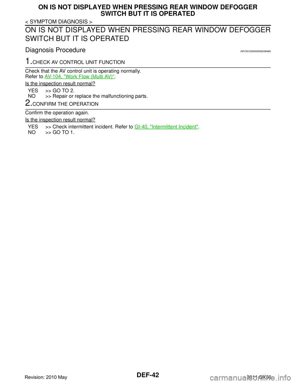
ON IS NOT DISPLAYED WHEN PRESSING REAR WINDOW DEFOGGER
SWITCH BUT IT IS OPERATED
ON IS NOT DISPLAYED WHEN PR ESSING REAR WINDOW DEFOGGER
SWITCH BUT IT IS OPERATED
Diagnosis ProcedureINFOID:0000000006299466
1.CHECK AV CONTROL UNIT FUNCTION
Check that the AV control unit is operating normally.
Refer to AV-104, "
Work Flow (Multi AV)".
Is the inspection result normal?
YES >> GO TO 2.
NO >> Repair or replace the malfunctioning parts.
2.CONFIRM THE OPERATION
Confirm the operation again.
Is the inspection result normal?
YES >> Check intermittent incident. Refer to GI-40, "Intermittent Incident".
NO >> GO TO 1.
Revision: 2010 May2011 QX56
Page 1540 of 5598

DLK-4
Component Function Check ................................145
Diagnosis Procedure .............................................145
COMBINATION METER BUZZER ..................146
Component Function Check .............................. ..146
Diagnosis Procedure .............................................146
INFORMATION DISPLAY ...............................147
Component Function Check .............................. ..147
Diagnosis Procedure .............................................147
KEY WARNING LAMP ....................................148
Component Function Check .............................. ..148
Diagnosis Procedure .............................................148
HAZARD FUNCTION .......................................149
Component Function Check .............................. ..149
Diagnosis Procedure .............................................149
AUTOMATIC BACK DOOR CLOSE SWITCH .150
Component Function Check .............................. ..150
Diagnosis Procedure .............................................150
Component Inspection ...........................................151
AUTOMATIC BACK DOOR MAIN SWITCH ...152
Component Function Check .............................. ..152
Diagnosis Procedure .............................................152
Component Inspection ...........................................153
AUTOMATIC BACK DOOR SWITCH .............154
Component Function Check .............................. ..154
Diagnosis Procedure .............................................154
Component Inspection ...........................................155
HALF LATCH SWITCH ...................................156
Component Function Check ................................ ..156
Diagnosis Procedure .............................................156
Component Inspection ...........................................157
TOUCH SENSOR ............................................158
RH ........................................................................... ..158
RH : Component Function Check ........................158
RH : Diagnosis Procedure .....................................158
RH : Component Inspection ..................................159
LH ........................................................................... ..159
LH : Component Function Check .........................159
LH : Diagnosis Procedure ......................................159
LH : Component Inspection ...................................160
BACK DOOR CLOSURE MOTOR ..................162
Diagnosis Procedure ........................................... ..162
AUTOMATIC BACK DOOR WARNING BUZZ-
ER ....................................................................
163
Diagnosis Procedure ........................................... ..163
Component Inspection ...........................................163
GROUND CIRCUIT ......................................... .165
Component Function Check .............................. ..165
Diagnosis Procedure .............................................165
INTEGRATED HOMELINK TRANSMITTER ....166
Component Function Check ............................... .166
Diagnosis Procedure .............................................166
SYMPTOM DIAGNOSIS ...........................168
DOOR DOES NOT LOCK/UNLOCK WITH
DOOR LOCK AND UNLOCK SWITCH .......... ..
168
ALL DOOR ............................................................. .168
ALL DOOR : Description .......................................168
ALL DOOR : Diagnosis Procedure .......................168
DRIVER SIDE ......................................................... .168
DRIVER SIDE : Description ..................................168
DRIVER SIDE : Diagnosis Procedure ...................168
PASSENGER SIDE .................................................168
PASSENGER SIDE : Descripti on .........................169
PASSENGER SIDE : Diagnos is Procedure ..........169
REAR LH ................................................................ .169
REAR LH : Description .........................................169
REAR LH : Diagnosis Procedure ..........................169
REAR RH ................................................................ .169
REAR RH : Description .........................................169
REAR RH : Diagnosis Procedure .........................169
DOOR DOES NOT LOCK/UNLOCK WITH
DOOR KEY CYLINDER OPERATION .............
171
Diagnosis Procedure ............................................ .171
DOOR DOES NOT LOCK/UNLOCK WITH
DOOR REQUEST SWITCH ..............................
172
ALL DOOR REQUEST SWITCHES ....................... .172
ALL DOOR REQUEST SWITCHES : Description .172
ALL DOOR REQUEST SWITCHES : Diagnosis
Procedure .............................................................
172
DRIVER SIDE DOOR REQUEST SWITCH ............ .173
DRIVER SIDE DOOR REQUEST SWITCH : De-
scription .................................................................
173
DRIVER SIDE DOOR REQUEST SWITCH : Diag-
nosis Procedure ....................................................
173
PASSENGER SIDE DOOR REQUEST SWITCH ... .173
PASSENGER SIDE DOOR REQUEST SWITCH :
Description ............................................................
173
PASSENGER SIDE DOOR REQUEST SWITCH :
Diagnosis Procedure .............................................
173
BACK DOOR REQUEST SWITCH ........................ .173
BACK DOOR REQUEST SWITCH : Description ..173
BACK DOOR REQUEST SWITCH : Diagnosis
Procedure .............................................................
173
DOOR DOES NOT LOCK/UNLOCK WITH IN-
TELLIGENT KEY ..............................................
175
Diagnosis Procedure ............................................ .175
Revision: 2010 May2011 QX56
Page 1549 of 5598
COMPONENT PARTSDLK-13
< SYSTEM DESCRIPTION >
C
DE
F
G H
I
J
L
M A
B
DLK
N
O P
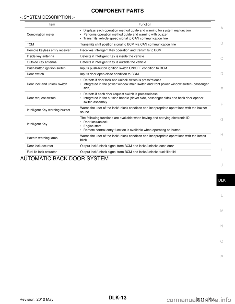
AUTOMATIC BACK DOOR SYSTEM
Combination meter Displays each operation method guide and warning for system malfunction
Performs operation method guide and warning with buzzer
Transmits vehicle speed signal to CAN communication line
TCM Transmits shift position signal to BCM via CAN communication line
Remote keyless entry receiver Receives Intelligent Key operation and transmits to BCM
Inside key antenna Detects if Intelligent Key is inside the vehicle
Outside key antenna Detects if Intelligent Key is outside the vehicle
Push-button ignition switch Inputs push-button ignition switch ON/OFF condition to BCM
Door switch Inputs door open/close condition to BCM
Door lock and unlock switch Detects if door lock and unlock switch is press/release
Integrated in the power window main switch and front power window switch (passenger
side)
Door request switch Detects if each door request switch is press/release
Integrated in the outside handle (driver side, passenger side) and back door opener
switch assembly
Intelligent Key warning buzzer Warns the user of the lock/unlock condition and inappropriate operations with the buzzer
sound
Intelligent Key The following functions are available when having and carrying electronic ID
Door lock/unlock
Engine start
Remote control entry function is available when operating on button
Hazard warning lamp Warns the user of the lock/unlock condition and inappropriate operations with the lamps
blink
Door lock actuator Output lock/unlock signal from BCM and locks/unlocks each door
Fuel lid lock actuator Output lock/unlock signal from BCM and locks/unlocks fuel filler lid Item Function
Revision: 2010 May2011 QX56
Page 1563 of 5598
SYSTEM (INTELLIGENT KEY SYSTEM)
DLK-27
< SYSTEM DESCRIPTION >
C
D E
F
G H
I
J
L
M A
B
DLK
N
O P
When the BCM detects that the Intelligent Key is within the outside key antenna detection area. BCM trans-
mits the request signal to the Intelligent Key and check it is near the door.
Intelligent Key receives the request signal and transmits the key ID signal to the BCM via remote keyless
entry receiver.
BCM receives the key ID signal and compares it with the registered key ID.
BCM illuminates lamps that are set, when key ID verification is OK.
TIMER FUNCTION
BCM can operate welcome light function, using the timer function, for 9 days, after key switch is turned OFF.
The timer function resets when the engine is started
*.Operating period of timer function may differ depending
on battery size.
*: Timer function does not stop if another Intelligent Key that has a different key ID is detected within the inte-
rior antenna detection area, when starting the engine.
OPERATION CONDITION
If the following condition are satisfi ed, welcome light function is operated.
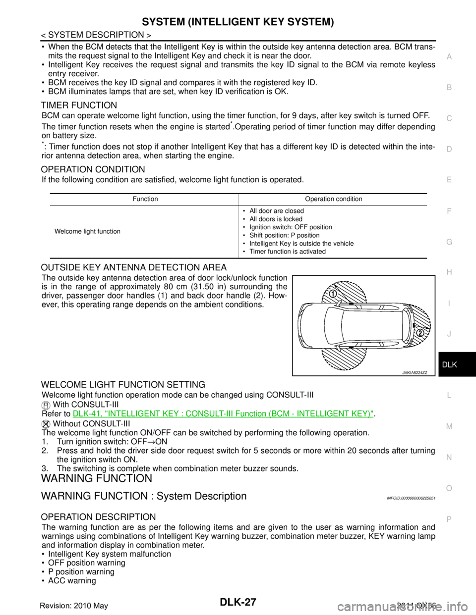
OUTSIDE KEY ANTENNA DETECTION AREA
The outside key antenna detection area of door lock/unlock function
is in the range of approximately 80 cm (31.50 in) surrounding the
driver, passenger door handles (1) and back door handle (2). How-
ever, this operating range depends on the ambient conditions.
WELCOME LIGHT FUNCTION SETTING
Welcome light function operation mode can be changed using CONSULT-III
With CONSULT-III
Refer to DLK-41, "
INTELLIGENT KEY : CONSULT-III F unction (BCM - INTELLIGENT KEY)".
Without CONSULT-III
The welcome light function ON/OFF can be s witched by performing the following operation.
1. Turn ignition switch: OFF →ON
2. Press and hold the driver side door request switch for 5 seconds or more within 20 seconds after turning the ignition switch ON.
3. The switching is complete when combination meter buzzer sounds.
WARNING FUNCTION
WARNING FUNCTION : System DescriptionINFOID:0000000006225851
OPERATION DESCRIPTION
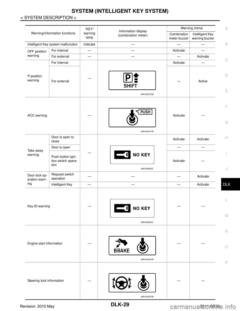
The warning function are as per the following items and are given to the user as warning information and
warnings using combinations of Intelligent Key warning buzzer, combination meter buzzer, KEY warning lamp
and information display in combination meter.
Intelligent Key system malfunction
OFF position warning
P position warning
ACC warning
Function Operation condition
Welcome light function All door are closed
All doors is locked
Ignition switch: OFF position
Shift position: P position
Intelligent Key is outside the vehicle
Timer function is activated
JMKIA5224ZZ
Revision: 2010 May2011 QX56
Page 1565 of 5598
SYSTEM (INTELLIGENT KEY SYSTEM)
DLK-29
< SYSTEM DESCRIPTION >
C
D E
F
G H
I
J
L
M A
B
DLK
N
O P
Warning/Information functions “KEY”
warning
lamp Information display
(combination meter) Warning chime
Combination
meter buzzer Intelligent Key
warning buzzer
Intelligent Key system malfunction Indicate — — —
OFF position
warning For internal — — Activate —
For external — — — Activate
P position
warning For internal
— Activate —
For external —Active
ACC warning — Activate —
Ta k e a w a y
warning Door is open to
close
— Activate Activate
Door is open ——
Push button-igni-
tion switch opera-
tion Activate —
Door lock op-
eration warn-
ing Request switch
operation
—— —Activate
Intelligent Key — — — Activate
Key ID warning — — —
Engine start information — — —
Steering lock information — — —
JMKIA0037GB
JMKIA0047GB
JMKIA4906ZZ
JMKIA4906ZZ
JMKIA0032GB
JMKIA0033GB
Revision: 2010 May2011 QX56
Page 1566 of 5598
DLK-30
< SYSTEM DESCRIPTION >
SYSTEM (INTELLIGENT KEY SYSTEM)
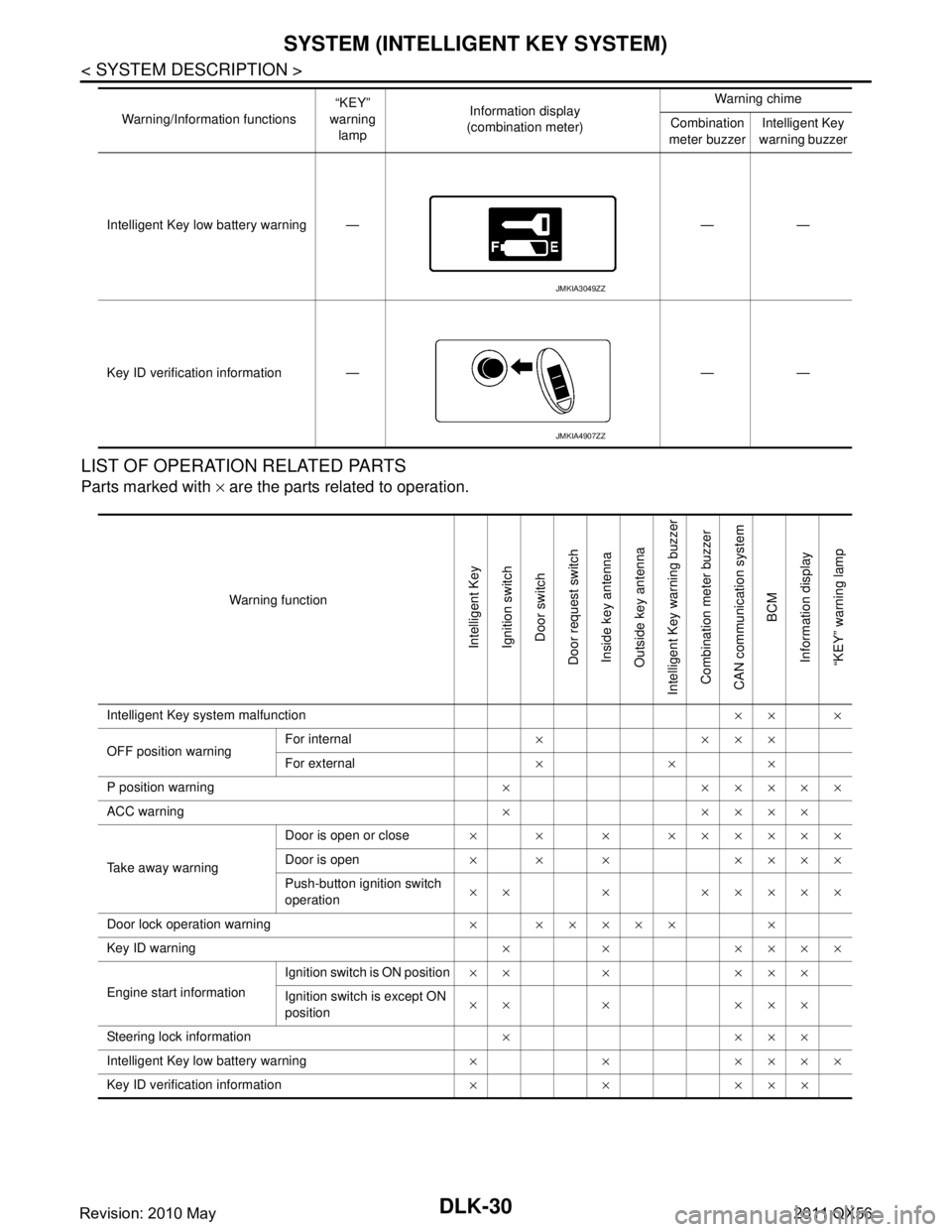
LIST OF OPERATION RELATED PARTS
Parts marked with × are the parts related to operation.
Intelligent Key low battery warning — — —
Key ID verification information — — — Warning/Information functions
“KEY”
warning lamp Information display
(combination meter) Warning chime
Combination
meter buzzer Intelligent Key
warning buzzer
JMKIA3049ZZ
JMKIA4907ZZ
Warning function
Intelligent Key
Ignition switch
Door switch
Door request switch Inside key antenna
Outside key antenna
Intelligent Key warning buzzer Combination meter buzzer
CAN communication system BCM
Information display
“KEY” warning lamp
Intelligent Key system malfunction ×× ×
OFF position warning For internal
××××
For external ×××
P position warning × ×××××
ACC warning ×××××
Take away warning Door is open or close
× × × ××××××
Door is open × × × ××××
Push-button ignition switch
operation ×× × ×××××
Door lock operation warning × ××××× ×
Key ID warning × × ××××
Engine start information Ignition switch is ON position
×× × ×××
Ignition switch is except ON
position ×× × ×××
Steering lock information ××××
Intelligent Key low battery warning × × ××××
Key ID verification information ×××××
Revision: 2010 May2011 QX56
Page 1574 of 5598
DLK-38
< SYSTEM DESCRIPTION >
DIAGNOSIS SYSTEM (BCM)
DIAGNOSIS SYSTEM (BCM)
COMMON ITEM
COMMON ITEM : CONSULT-III Function (BCM - COMMON ITEM)INFOID:0000000006307583
APPLICATION ITEM
CONSULT-III performs the following functions via CAN communication with BCM.
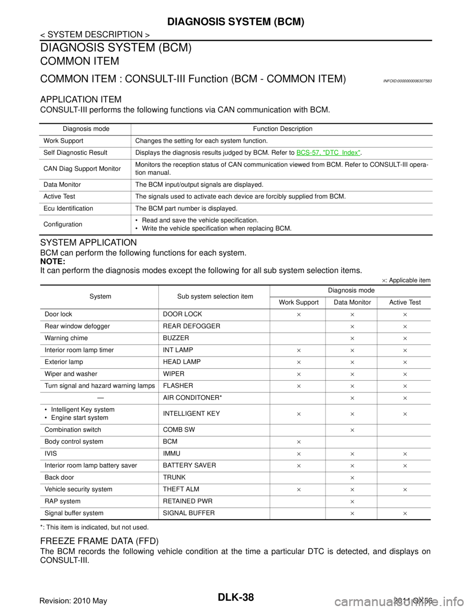
SYSTEM APPLICATION
BCM can perform the following functions for each system.
NOTE:
It can perform the diagnosis modes except the following for all sub system selection items.
×: Applicable item
*: This item is indicated, but not used.
FREEZE FRAME DATA (FFD)
The BCM records the following vehicle condition at the time a particular DTC is detected, and displays on
CONSULT-III.
Diagnosis mode Function Description
Work Support Changes the setting for each system function.
Self Diagnostic Result Displays the diagnosis results judged by BCM. Refer to BCS-57, "
DTCIndex".
CAN Diag Support Monitor Monitors the reception status of CAN communication viewed from BCM. Refer to CONSULT-III opera-
tion manual.
Data Monitor The BCM input/output signals are displayed.
Active Test The signals used to activate ea ch device are forcibly supplied from BCM.
Ecu Identification The BCM part number is displayed.
Configuration Read and save the vehicle specification.
Write the vehicle specification when replacing BCM.
System Sub system selection item Diagnosis mode
Work Support Data Monitor Active Test
Door lock DOOR LOCK ×××
Rear window defogger REAR DEFOGGER ××
Warning chime BUZZER ××
Interior room lamp timer INT LAMP ×××
Exterior lamp HEAD LAMP ×××
Wiper and washer WIPER ×××
Turn signal and hazard warning lamps FLASHER ×××
— AIR CONDITONER* ××
Intelligent Key system
Engine start system INTELLIGENT KEY
×××
Combination switch COMB SW ×
Body control system BCM ×
IVIS IMMU ×××
Interior room lamp battery saver BATTERY SAVER ×××
Back door TRUNK ×
Vehicle security system THEFT ALM ×××
RAP system RETAINED PWR ×
Signal buffer system SIGNAL BUFFER ××
Revision: 2010 May2011 QX56
Page 1576 of 5598

DLK-40
< SYSTEM DESCRIPTION >
DIAGNOSIS SYSTEM (BCM)
DATA MONITOR
ACTIVE TEST
INTELLIGENT KEY
Monitor item Description
DOOR LOCK-UNLOCK SET Selective unlock function mode can be changed to operation with this mode
On: Operate
Off: Non-operation
AUTOMATIC DOOR LOCK SE-
LECT Automatic door lock function mode can be se
lected from the following in this mode
VH SPD: All doors are locked when vehicle speed more than 24 km/h (15 MPH)
P RANGE: All doors are locked when shifting the selector lever from P position to other than the P position
AUTOMATIC DOOR UNLOCK
SELECT Automatic door unlock function mode can be
selected from the following in this mode
MODE 1: All doors are unlocked when the power supply position is changed from ON to OFF
MODE 2: All doors are unlocked when shifting the selector lever from any position other
than the P to P position
MODE 3: Driver side door is unlocked when the power supply position is changed from ON to OFF
MODE 4: Driver side door is unlocked when shifting the selector lever from any position oth- er than the P to P position
MODE 5: This item is displayed, but cannot be used
MODE 6: This item is displayed, but cannot be used
AUTOMATIC LOCK/UNLOCK
SET Automatic door lock/unlock function mode can be selected from the following in this mode
Off: Non-operation
Unlock Only: Door unlock operation only
Lock Only: Door lock operation only
Lock/Unlock: Lock and unlock operation
Monitor Item Contents
REQ SW-DR Indicated [On/Off] condition of door request switch (driver side)
REQ SW-AS Indicated [On/Off] condition of door request switch (passenger side)
REQ SW-BD/TR Indicated [On/Off] condition of back door request switch
DOOR SW-DR Indicated [On/Off] condition of front door switch (driver side)
DOOR SW-AS Indicated [On/Off] condition of front door switch (passenger side)
DOOR SW-RR Indicated [On/Off] condition of rear door switch RH
DOOR SW-RL Indicated [On/Off] condition of rear door switch LH
DOOR SW-BK Indicated [On/Off] condition of back door switch
CDL LOCK SW Indicated [On/Off] condition of lock signal from door lock unlock switch
CDL UNLOCK SW Indicated [On/Off] condition of unlock signal from door lock unlock switch
KEY CYL LK-SW Indicated [On/Off] condition of lock signal from door key cylinder switch
KEY CYL UN-SW Indicated [On/Off] condition of unlock signal from door key cylinder switch
Te s t i t e m D e s c r i p t i o n
DOOR LOCK This test is able to check door lock/unlock operation
The all door lock actuators are locked when “ALL LOCK” on CONSULT-III screen is touched
The all door lock actuators are unlocked when “ALL UNLK” on CONSULT-III screen is touched
The front door lock actuator (driver side) is unlocked when “DR UNLK” on CONSULT-III screen
is touched
The front door lock actuator (passenger side) is unlocked when “AS UNLK” on CONSULT- III screen is touched
The door lock actuator (other) is unlocked wh en “OTR ULK” on CONSULT-III screen is touched
Revision: 2010 May2011 QX56