2011 INFINITI QX56 ABS
[x] Cancel search: ABSPage 2873 of 5598
EXT-18
< REMOVAL AND INSTALLATION >
REAR BUMPER
Bumper protector (LH and RH)
Bumper side reinforcement (LH and RH)
10. Remove energy absorber.
INSTALLATION
Note the following item, and then install in the reverse order of removal.
NOTE:
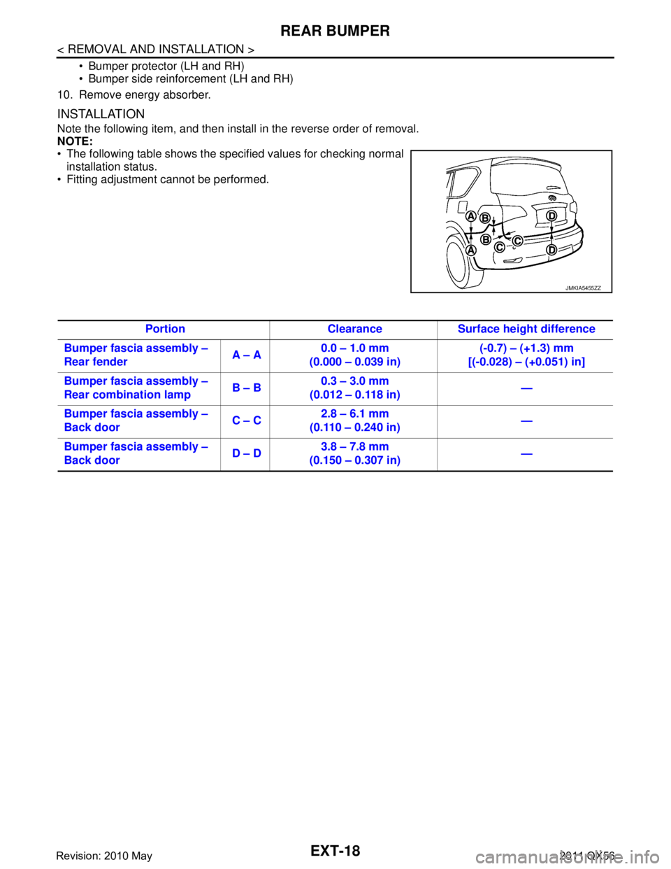
The following table shows the specified values for checking normal installation status.
Fitting adjustment cannot be performed.
JMKIA5455ZZ
Portion Clearance Surface height difference
Bumper fascia assembly –
Rear fender A – A0.0 – 1.0 mm
(0.000 – 0.039 in) (-0.7) – (+1.3) mm
[(-0.028) – (+0.051) in]
Bumper fascia assembly –
Rear combination lamp B – B0.3 – 3.0 mm
(0.012 – 0.118 in) —
Bumper fascia assembly –
Back door C – C2.8 – 6.1 mm
(0.110 – 0.240 in) —
Bumper fascia assembly –
Back door D – D3.8 – 7.8 mm
(0.150 – 0.307 in) —
Revision: 2010 May2011 QX56
Page 2909 of 5598
![INFINITI QX56 2011 Factory Service Manual
FRONT WHEEL HUB AND KNUCKLEFAX-9
< REMOVAL AND INSTALLATION > [2WD]
C
EF
G H
I
J
K L
M A
B
FA X
N
O P
8. Remove shock absorber mounting bolt from lower link. Refer to FSU-10, "Removal and Installati INFINITI QX56 2011 Factory Service Manual
FRONT WHEEL HUB AND KNUCKLEFAX-9
< REMOVAL AND INSTALLATION > [2WD]
C
EF
G H
I
J
K L
M A
B
FA X
N
O P
8. Remove shock absorber mounting bolt from lower link. Refer to FSU-10, "Removal and Installati](/manual-img/42/57033/w960_57033-2908.png)
FRONT WHEEL HUB AND KNUCKLEFAX-9
< REMOVAL AND INSTALLATION > [2WD]
C
EF
G H
I
J
K L
M A
B
FA X
N
O P
8. Remove shock absorber mounting bolt from lower link. Refer to FSU-10, "Removal and Installation".
9. Separate upper link from steering knuckle, using the ball joint remover (commercial service tool), and
remove upper link.
CAUTION:
Temporarily tighten the nut to prevent damage to threads and to prevent the ball joint remover
from suddenly coming off.
Never damage ball joint boot.
10. Remove wheel hub and bearing assembly, and then remove splash guard.
11. Remove lower link from steering knuckle. CAUTION:
Never damage ball joint boot.
12. Remove steering knuckle.
13. Remove hub bolts (1) from wheel hub and bearing assembly, using the ball joint remover (A) (commercial service tool).
CAUTION:
Remove hub bolt only when necessary.
Never hammer the hub bolt to avoid impact to the wheel
hub and bearing assembly.
Pull out the hub bolt in a di rection perpendicular to the
wheel hub and bearing assembly.
14. Perform inspection after removal. Refer to FAX-9, "
Inspection".
INSTALLATION
Note the following, and install in the reverse order of removal.
Place a suitable washer (A) as shown in the figure to install the hub
bolts (1) by using the tightening force of the nut (B).
CAUTION:
Check that there is no cl earance between wheel hub and
bearing assembly, and hub bolt.
Never reuse hub bolt.
Perform the final tightening of each of parts under unladen condi-
tions, which were removed when removing wheel hub and bearing
assembly and steering knuckle.
Never reuse cotter pin.
Perform inspection after installation. Refer to FA X - 9 , "
Inspection".
InspectionINFOID:0000000006225420
INSPECTION AFTER REMOVAL
Check components for deformation, cracks, and other damage. Replace it if necessary.
Ball Joint Inspection
Check boots of lower link and steering outer socket ba ll joint for breakage, axial play, and torque. Refer to
FSU-15, "
Inspection" and ST-46, "Inspection".
INSPECTION AFTER INSTALLATION
1. Check wheel sensor harness for proper connection. Refer to BRC-134, "FRONT WHEEL SENSOR :
Exploded View".
2. Check the wheel alignment. Refer to FSU-7, "
Inspection".
3. Adjust neutral position of steering angle sensor. Refer to BRC-64, "
Work Procedure".
JPDIF0299ZZ
JPDIF0300ZZ
Revision: 2010 May2011 QX56
Page 2919 of 5598
![INFINITI QX56 2011 Factory Service Manual
FRONT WHEEL HUB AND KNUCKLEFAX-19
< REMOVAL AND INSTALLATION > [4WD]
C
EF
G H
I
J
K L
M A
B
FA X
N
O P
7. Set suitable jack under lower link.
8. Remove shock absorber mounting bolt from lower link. R INFINITI QX56 2011 Factory Service Manual
FRONT WHEEL HUB AND KNUCKLEFAX-19
< REMOVAL AND INSTALLATION > [4WD]
C
EF
G H
I
J
K L
M A
B
FA X
N
O P
7. Set suitable jack under lower link.
8. Remove shock absorber mounting bolt from lower link. R](/manual-img/42/57033/w960_57033-2918.png)
FRONT WHEEL HUB AND KNUCKLEFAX-19
< REMOVAL AND INSTALLATION > [4WD]
C
EF
G H
I
J
K L
M A
B
FA X
N
O P
7. Set suitable jack under lower link.
8. Remove shock absorber mounting bolt from lower link. Refer to FSU-10, "
Removal and Installation".
9. Separate upper link from steering knuckle, using the ball joint remover (commercial service tool), and
remove upper link.
CAUTION:
Temporarily tighten the nut to prevent damage to threads and to prevent the ball joint remover
from suddenly coming off.
Never damage ball joint boot.
10. Remove cotter pin, and then loosen wheel hub lock nut.
11. Put matching mark on drive shaft and wheel hub and bearing assembly. CAUTION:
Use paint or similar substance for matc hing marks. Never scratch the surface.
12. Patch wheel hub lock nut with a piece of wood. Hammer the wood to disengage wheel hub and bearing assembly from drive shaft.
CAUTION:
Never place drive shaft joint at an extreme angle. Also be careful not to overextend slide joint.
Never allow drive shaft to hang down without support for or joint sub-assembly, shaft and the
other parts.
NOTE:
Use suitable puller, if wheel hub and bearing assembly and drive shaft cannot be separated even after
performing the above procedure.
13. Remove wheel hub lock nut.
14. Remove wheel hub and bearing assembly, and then remove splash guard.
15. Remove lower link from steering knuckle. CAUTION:
Never damage ball joint boot.
16. Remove steering knuckle.
17. Remove hub bolts (1) from wheel hub and bearing assembly, using the ball joint remover (A) (commercial service tool).
CAUTION:
Remove hub bolt only when necessary.
Never hammer the hub bolt to avoid impact to the wheel
hub and bearing assembly.
Pull out the hub bolt in a di rection perpendicular to the
wheel hub and bearing assembly.
18. Perform inspection after removal. Refer to FAX-20, "
Inspection".
INSTALLATION
Note the following, and install in the reverse order of removal.
Place a suitable washer (A) as shown in the figure to install the hub
bolts (1) by using the tightening force of the nut (B).
CAUTION:
Check that there is no cl earance between wheel hub and
bearing assembly, and hub bolt.
Never reuse hub bolt.
Use the following torque range for tightening the wheel hub lock nut.
CAUTION:
Since the drive shaft is assembled by press-fitting , use the tightening torque range for the wheel
hub lock nut.
Be sure to use torque wrench to tighten th e wheel hub lock nut. Never use a power tool.
Perform the final tightening of each of parts under unladen conditions, which were removed when removing
wheel hub and bearing assembly and steering knuckle.
JPDIF0299ZZ
: 118 – 123 N·m (12.1 – 12.5 kg-m, 87 – 90 ft-lb)
JPDIF0300ZZ
Revision: 2010 May2011 QX56
Page 2922 of 5598
![INFINITI QX56 2011 Factory Service Manual
FAX-22
< REMOVAL AND INSTALLATION >[4WD]
FRONT DRIVE SHAFT
FRONT DRIVE SHAFT
Exploded ViewINFOID:0000000006225402
Removal and InstallationINFOID:0000000006225403
REMOVAL
1. Remove tires.
2. Remove br INFINITI QX56 2011 Factory Service Manual
FAX-22
< REMOVAL AND INSTALLATION >[4WD]
FRONT DRIVE SHAFT
FRONT DRIVE SHAFT
Exploded ViewINFOID:0000000006225402
Removal and InstallationINFOID:0000000006225403
REMOVAL
1. Remove tires.
2. Remove br](/manual-img/42/57033/w960_57033-2921.png)
FAX-22
< REMOVAL AND INSTALLATION >[4WD]
FRONT DRIVE SHAFT
FRONT DRIVE SHAFT
Exploded ViewINFOID:0000000006225402
Removal and InstallationINFOID:0000000006225403
REMOVAL
1. Remove tires.
2. Remove brake hose bracket. Refer to
BR-23, "
FRONT : Removal and Installation".
3. Remove caliper assembly mounting bolts. Hang caliper assembly in a place where it will not interfere with work. Refer to BR-37, "
BRAKE CALIPER ASSEMBLY : Removal and Installation".
CAUTION:
Never depress brake pedal while brake caliper is removed.
4. Remove disc rotor. Refer to FAX-18, "
Removal and Installation".
5. Remove wheel sensor harness. Refer to BRC-134, "
FRONT WHEEL SENSOR : Removal and Installa-
tion".
CAUTION:
Never pull on wheel sensor harness.
6. Remove height sensor from upper link (right side). Refer to EXL-136, "
Removal and Installation".
7. Remove steering outer socket. Refer to ST-42, "
Removal and Installation".
8. Set suitable jack under lower link.
9. Remove shock absorber mounting bolt from lower link. Refer to FSU-10, "
Removal and Installation".
10. Separate upper link from steering knuckle, using t he ball joint remover (commercial service tool), and
remove upper link.
CAUTION:
Temporarily tighten the nut to prevent damage to threads and to prevent the ball joint remover
from suddenly coming off.
1. Circular clip 2. Dust shield 3. Housing
4. Snap ring 5. Ball cage/steel ball/inner race assem-
bly6. Stopper ring
7. Boot band 8. Boot 9. Shaft
10. Circular clip 11. Joint sub-assembly : Wheel side
: NISSAN genuine grease or an equivalent.
Refer to GI-4, "
Components" for symbols not described on the above.
JPDIF0279ZZ
Revision: 2010 May2011 QX56
Page 2935 of 5598
FL-6
< REMOVAL AND INSTALLATION >
FUEL LEVEL SENSOR UNIT, FUEL FILTER AND FUEL PUMP ASSEMBLY
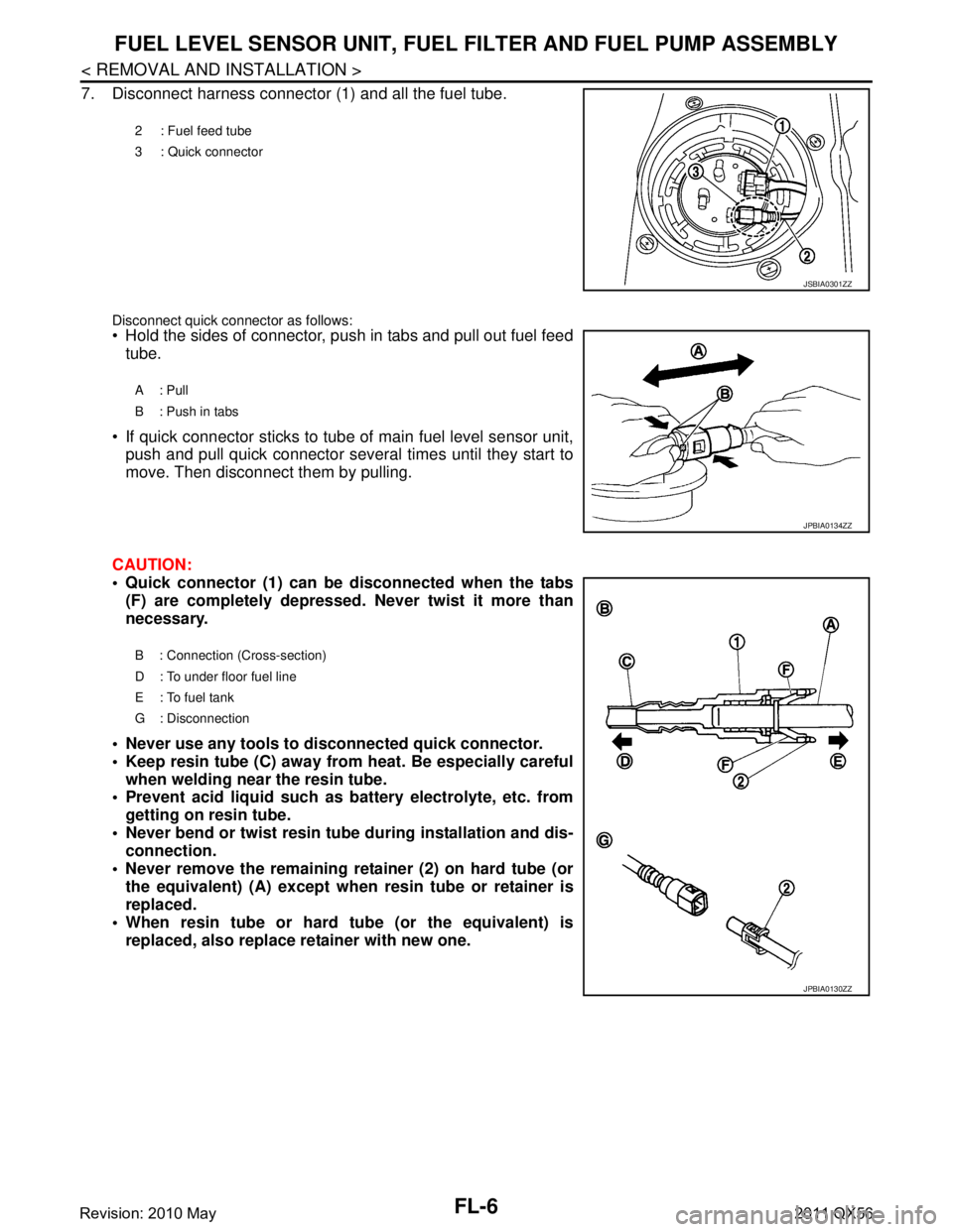
7. Disconnect harness connector (1) and all the fuel tube.
Disconnect quick connector as follows: Hold the sides of connector, push in tabs and pull out fuel feed
tube.
If quick connector sticks to tube of main fuel level sensor unit, push and pull quick connector several times until they start to
move. Then disconnect them by pulling.
CAUTION:
Quick connector (1) can be disconnected when the tabs (F) are completely depressed. Never twist it more than
necessary.
Never use any tools to di sconnected quick connector.
Keep resin tube (C) away from heat. Be especially careful when welding near the resin tube.
Prevent acid liquid such as battery electrolyte, etc. from
getting on resin tube.
Never bend or twist resin tube during installation and dis- connection.
Never remove the remaining retainer (2) on hard tube (or the equivalent) (A) except when resin tube or retainer is
replaced.
When resin tube or hard tube (or the equivalent) is replaced, also replace retainer with new one.
2 : Fuel feed tube
3 : Quick connector
JSBIA0301ZZ
A: Pull
B : Push in tabs
JPBIA0134ZZ
B : Connection (Cross-section)
D : To under floor fuel line
E : To fuel tank
G : Disconnection
JPBIA0130ZZ
Revision: 2010 May2011 QX56
Page 2936 of 5598
FUEL LEVEL SENSOR UNIT, FUEL FILTER AND FUEL PUMP ASSEMBLY
FL-7
< REMOVAL AND INSTALLATION >
C
D E
F
G H
I
J
K L
M A
FL
NP
O
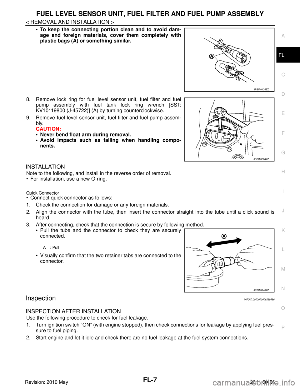
To keep the connecting portio
n clean and to avoid dam-
age and foreign materials, cover them completely with
plastic bags (A) or something similar.
8. Remove lock ring for fuel level sensor unit, fuel filter and fuel pump assembly with fuel tank lock ring wrench [SST:
KV10119800 (J-45722)] (A) by turning counterclockwise.
9. Remove fuel level sensor unit, fuel filter and fuel pump assem- bly.
CAUTION:
Never bend float arm during removal.
Avoid impacts such as fa lling when handling compo-
nents.
INSTALLATION
Note to the following, and install in the reverse order of removal.
For installation, use a new O-ring.
Quick Connector Connect quick connector as follows:
1. Check the connection for damage or any foreign materials.
2. Align the connector with the tube, then insert the connector straight into the tube until a click sound is
heard.
3. After connecting, check that the connection is secure by following method. Pull the tube and the connector to check they are securely
connected.
Visually confirm that the two retainer tabs are connected to the connector.
InspectionINFOID:0000000006289686
INSPECTION AFTER INSTALLATION
Use the following procedure to check for fuel leakage.
1. Turn ignition switch “ON” (with engine stopped), then check connections for leakage by applying fuel pres-
sure to fuel piping.
2. Start engine and let it idle and check there are no fuel leakage at the fuel system connections.
JPBIA0135ZZ
JSBIA0384ZZ
A: Pull
JPBIA0140ZZ
Revision: 2010 May2011 QX56
Page 2946 of 5598
FSU-4
< PREPARATION >
PREPARATION
PREPARATION
PREPARATION
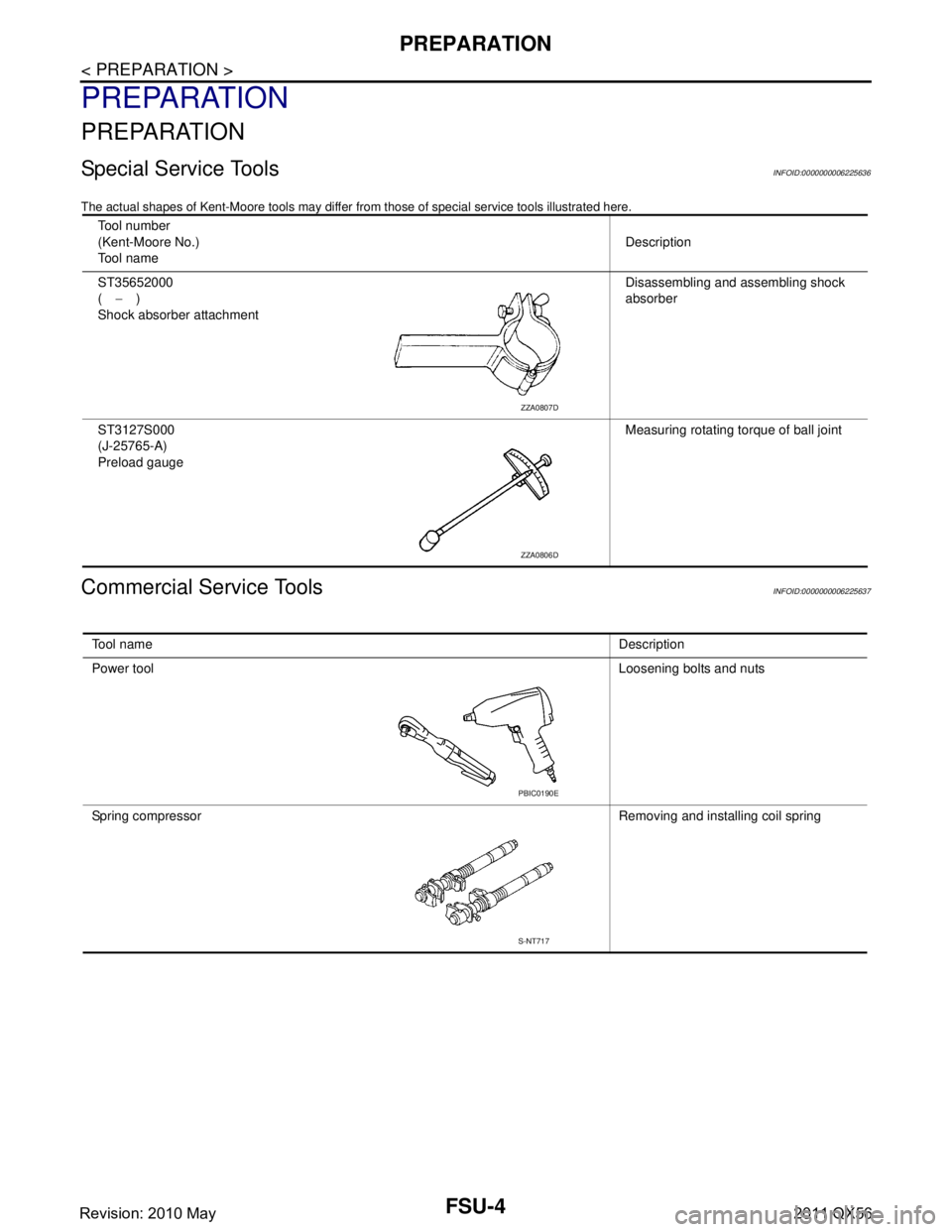
Special Service ToolsINFOID:0000000006225636
The actual shapes of Kent-Moore tools may differ from those of special service tools illustrated here.
Commercial Service ToolsINFOID:0000000006225637
Tool number
(Kent-Moore No.)
Tool name Description
ST35652000
( − )
Shock absorber attachment Disassembling and assembling shock
absorber
ST3127S000
(J-25765-A)
Preload gauge Measuring rotating torque of ball joint
ZZA0807D
ZZA0806D
Tool name
Description
Power tool Loosening bolts and nuts
Spring compressor Removing and installing coil spring
PBIC0190E
S-NT717
Revision: 2010 May2011 QX56
Page 2947 of 5598
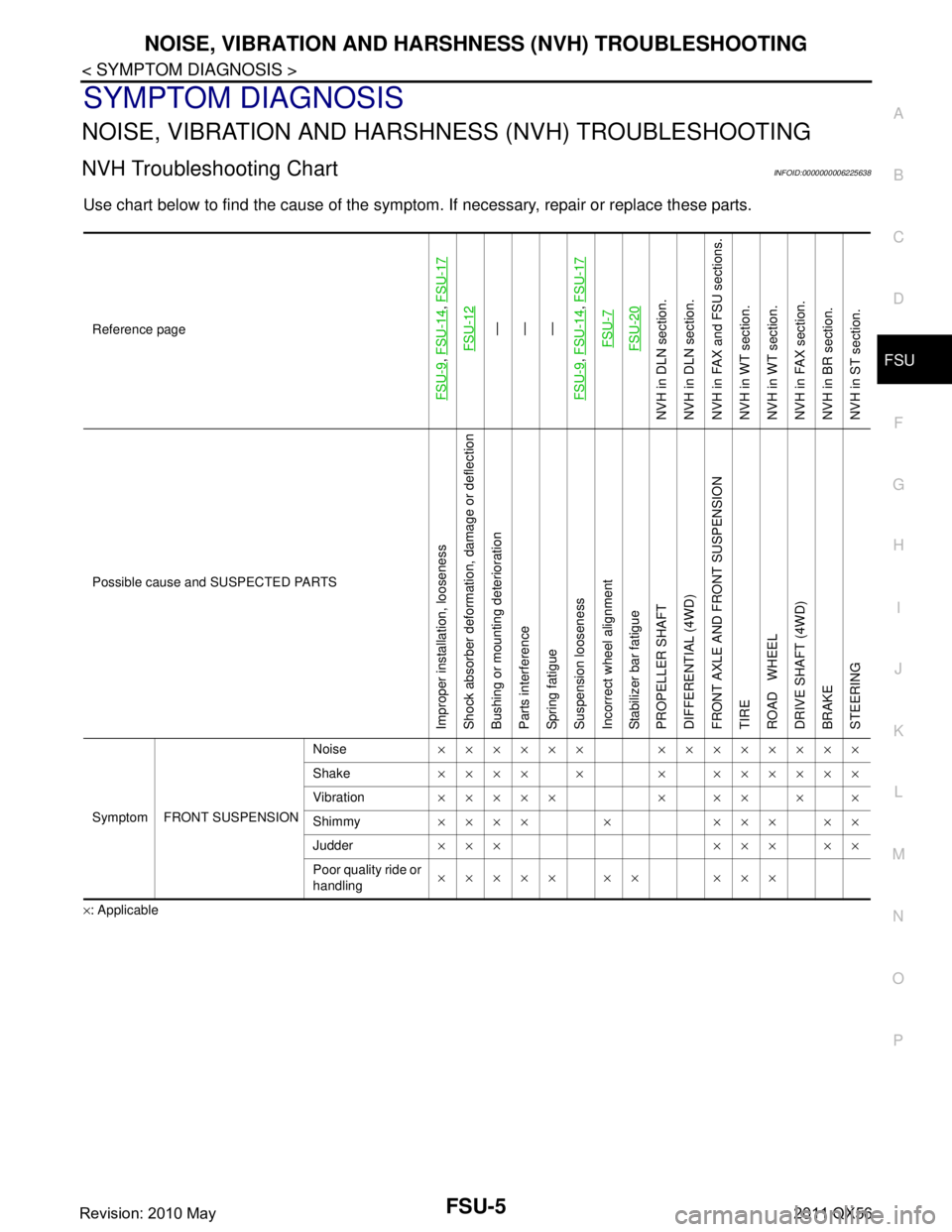
NOISE, VIBRATION AND HARSHNESS (NVH) TROUBLESHOOTINGFSU-5
< SYMPTOM DIAGNOSIS >
C
DF
G H
I
J
K L
M A
B
FSU
N
O P
SYMPTOM DIAGNOSIS
NOISE, VIBRATION AND HARSHN ESS (NVH) TROUBLESHOOTING
NVH Troubleshooting ChartINFOID:0000000006225638
Use chart below to find the cause of the symptom. If necessary, repair or replace these parts.
×: ApplicableReference page
FSU-9
,
FSU-14
, FSU-17
FSU-12
—
—
—
FSU-9
, FSU-14
, FSU-17
FSU-7FSU-20
NVH in DLN section.
NVH in DLN section.
NVH in FAX and FSU sections.
NVH in WT section.
NVH in WT section.
NVH in FAX section.
NVH in BR section.
NVH in ST section.
Possible cause and SUSPECTED PARTS
Improper installation, looseness
Shock absorber deformation, damage or deflection
Bushing or mounting deterioration
Parts interference
Spring fatigue
Suspension looseness
Incorrect wheel alignment
Stabilizer bar fatigue
PROPELLER SHAFT
DIFFERENTIAL (4WD)
FRONT AXLE AND FRONT SUSPENSION
TIRE
ROAD WHEEL
DRIVE SHAFT (4WD)
BRAKE
STEERING
Symptom FRONT SUSPENSION Noise
×××××× ××××××××
Shake ×××× × × ××××××
Vibration ××××× × ×× × ×
Shimmy ×××× × ××× ××
Judder ××× ××× ××
Poor quality ride or
handling ××××× ×× ×××
Revision: 2010 May2011 QX56