2011 INFINITI QX56 ABS
[x] Cancel search: ABSPage 2957 of 5598
LOWER LINKFSU-15
< REMOVAL AND INSTALLATION >
C
DF
G H
I
J
K L
M A
B
FSU
N
O P
12. Separate drive shaft from steering knuckle. (4WD) Refer to FAX-22, "Removal and Installation".
13. Remove lower link from steering knuckle. Refer to FA X - 8 , "
Removal and Installation" (2WD), FAX-18,
"Removal and Installation" (4WD).
14. Remove protector A. (With HBMC) Refer to SCS-32, "
FRONT TUBE ASSEMBLY : Removal and Installa-
tion".
15. Remove bracket. (With HBMC) Refer to SCS-32, "
FRONT TUBE ASSEMBLY : Removal and Installation".
16. Remove adjusting bolts, nuts, eccentric discs, stopper rubber, and lower link from vehicle.
17. Remove bump rubber from lower link.
18. Perform inspection after removal. Refer to FSU-15, "
Inspection".
INSTALLATION
Note the following, and install in the reverse order of removal.
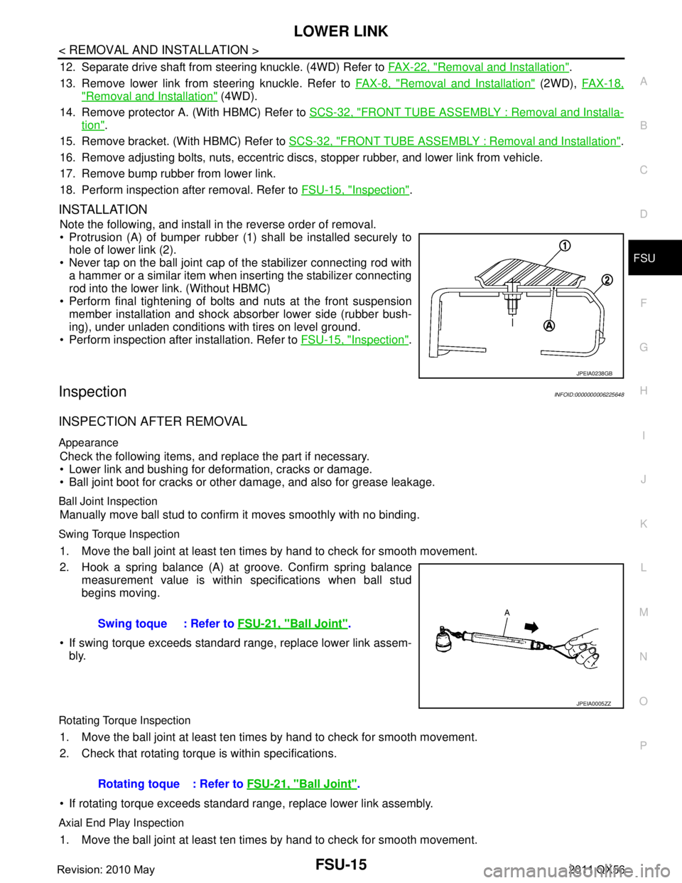
Protrusion (A) of bumper rubber (1) shall be installed securely to
hole of lower link (2).
Never tap on the ball joint cap of the stabilizer connecting rod with a hammer or a similar item when inserting the stabilizer connecting
rod into the lower link. (Without HBMC)
Perform final tightening of bolts and nuts at the front suspension member installation and shock absorber lower side (rubber bush-
ing), under unladen conditions with tires on level ground.
Perform inspection after installation. Refer to FSU-15, "
Inspection".
InspectionINFOID:0000000006225648
INSPECTION AFTER REMOVAL
Appearance
Check the following items, and replace the part if necessary.
Lower link and bushing for deformation, cracks or damage.
Ball joint boot for cracks or other damage, and also for grease leakage.
Ball Joint Inspection
Manually move ball stud to confirm it moves smoothly with no binding.
Swing Torque Inspection
1. Move the ball joint at least ten times by hand to check for smooth movement.
2. Hook a spring balance (A) at groove. Confirm spring balance
measurement value is within specifications when ball stud
begins moving.
If swing torque exceeds standard range, replace lower link assem- bly.
Rotating Torque Inspection
1. Move the ball joint at least ten times by hand to check for smooth movement.
2. Check that rotating torque is within specifications.
If rotating torque exceeds standard range, replace lower link assembly.
Axial End Play Inspection
1. Move the ball joint at least ten times by hand to check for smooth movement.
JPEIA0238GB
Swing toque : Refer to FSU-21, "Ball Joint".
JPEIA0005ZZ
Rotating toque : Refer to FSU-21, "Ball Joint".
Revision: 2010 May2011 QX56
Page 2978 of 5598
GI-14
< HOW TO USE THIS MANUAL >
ABBREVIATIONS
ABBREVIATIONS
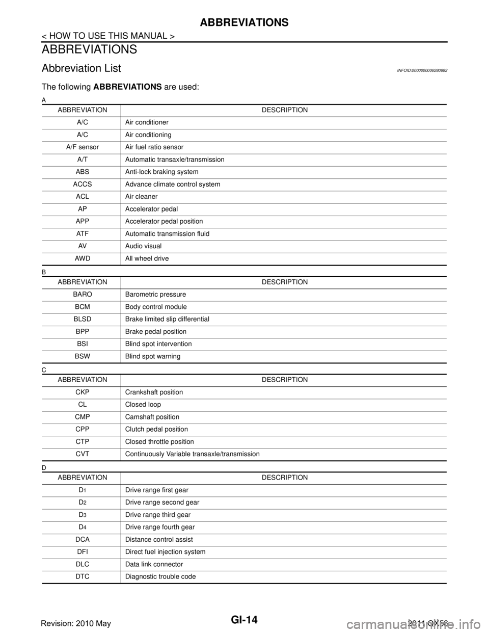
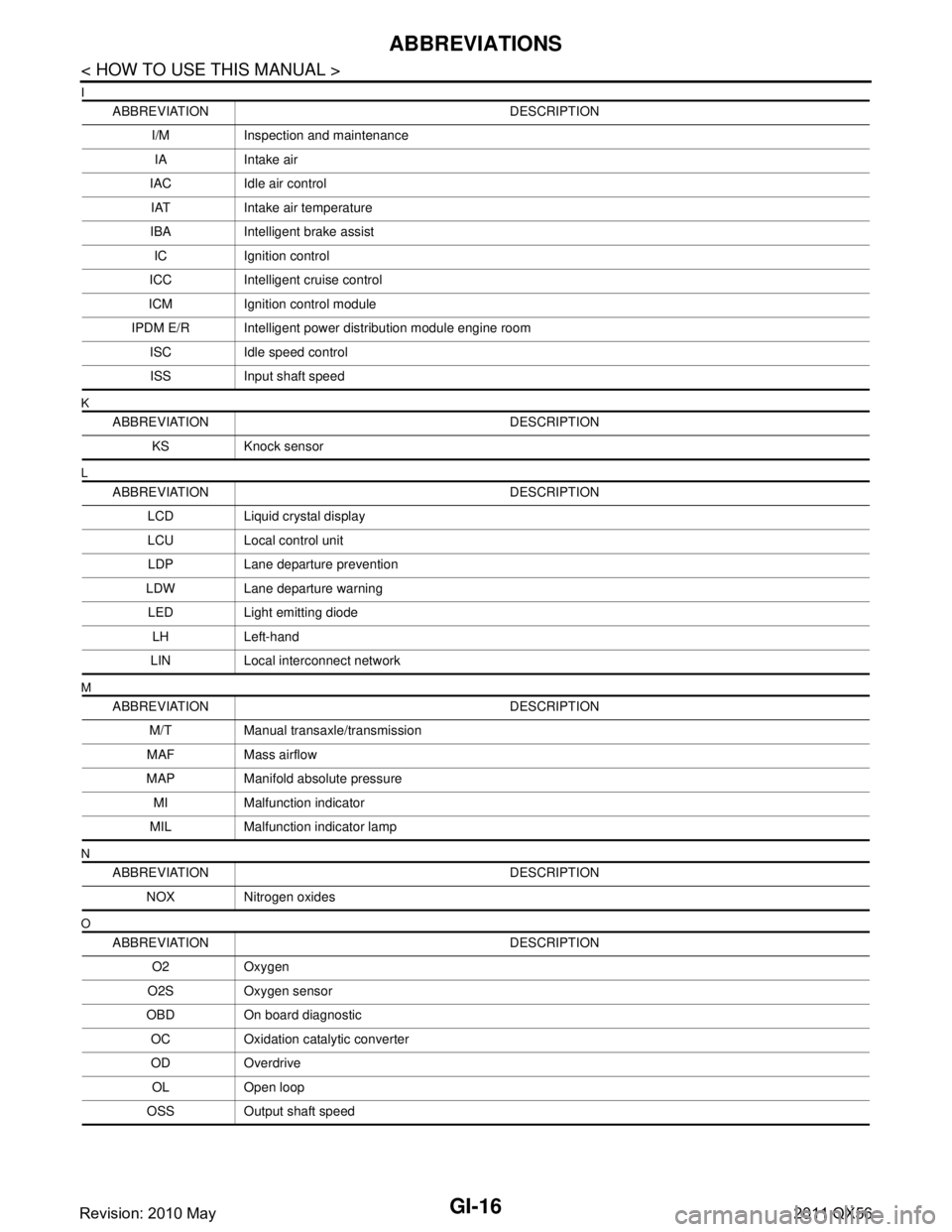
Abbreviation ListINFOID:0000000006280882
The following ABBREVIATIONS are used:
A
B
C
D
ABBREVIATION DESCRIPTION
A/C Air conditioner
A/C Air conditioning
A/F sensor Air fuel ratio sensor A/T Automatic transaxle/transmission
ABS Anti-lock braking system
ACCS Advance climate control system ACL Air cleaner
AP Accelerator pedal
APP Accelerator pedal position ATF Automatic transmission fluid AV Audio visual
AWD All wheel drive
ABBREVIATION DESCRIPTION BARO Barometric pressureBCM Body control module
BLSD Brake limited slip differential BPP Brake pedal positionBSI Blind spot intervention
BSW Blind spot warning
ABBREVIATION DESCRIPTION CKP Crankshaft positionCL Closed loop
CMP Camshaft position CPP Clutch pedal positionCTP Closed throttle position
CVT Continuously Variable transaxle/transmission
ABBREVIATION DESCRIPTION D
1Drive range first gear
D
2Drive range second gear
D
3Drive range third gear
D
4Drive range fourth gear
DCA Distance control assist DFI Direct fuel injection system
DLC Data link connector
DTC Diagnostic trouble code
Revision: 2010 May2011 QX56
Page 2980 of 5598
GI-16
< HOW TO USE THIS MANUAL >
ABBREVIATIONS
I
K
L
M
N
O
ABBREVIATION DESCRIPTIONI/M Inspection and maintenanceIA Intake air
IAC Idle air control IAT Intake air temperature
IBA Intelligent brake assist IC Ignition control
ICC Intelligent cruise control
ICM Ignition control module
IPDM E/R Intelligent power distribution module engine room ISC Idle speed controlISS Input shaft speed
ABBREVIATION DESCRIPTION KS Knock sensor
ABBREVIATION DESCRIPTION LCD Liquid crystal display
LCU Local control unitLDP Lane departure prevention
LDW Lane departure warning LED Light emitting diode LH Left-hand
LIN Local interconnect network
ABBREVIATION DESCRIPTION M/T Manual transaxle/transmission
MAF Mass airflow
MAP Manifold absolute pressure MI Malfunction indicator
MIL Malfunction indicator lamp
ABBREVIATION DESCRIPTION NOX Nitrogen oxides
ABBREVIATION DESCRIPTION O2 Oxygen
O2S Oxygen sensor
OBD On board diagnostic OC Oxidation catalytic converter
OD OverdriveOL Open loop
OSS Output shaft speed
Revision: 2010 May2011 QX56
Page 3012 of 5598
GI-48
< BASIC INSPECTION >
CONSULT-III/GST CHECKING SYSTEM
CONSULT-III/GST CHECKING SYSTEM
DescriptionINFOID:0000000006280856
When CONSULT-III/GST is connected with a data link connector
(A) equipped on the vehicle side, it will communicate with the con-
trol unit equipped in the vehicle and then enable various kinds of
diagnostic tests.
Refer to “CONSULT-III Software Operation Manual” for more infor- mation.
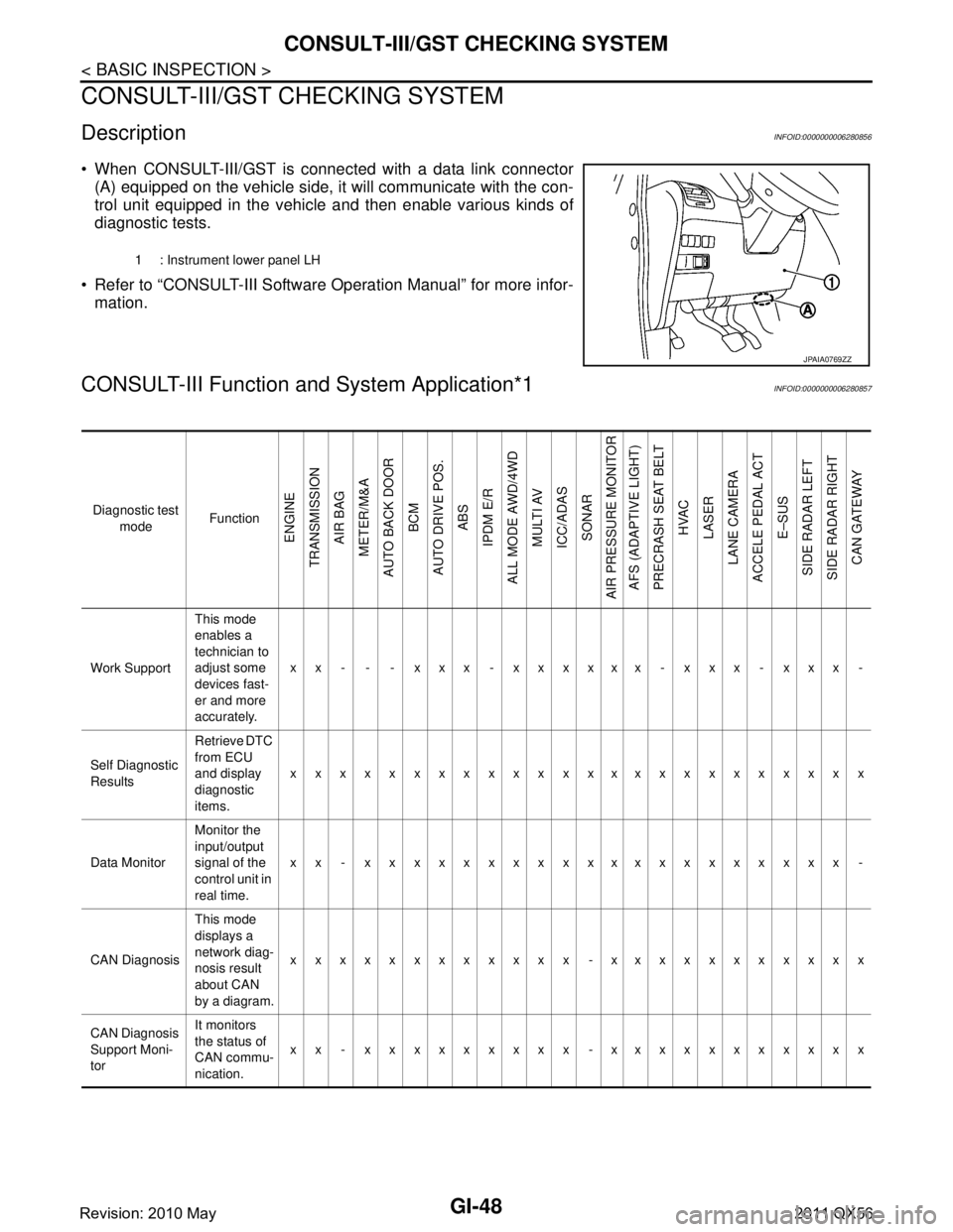
CONSULT-III Function a nd System Application*1INFOID:0000000006280857
1 : Instrument lower panel LH
JPAIA0769ZZ
Diagnostic test
mode Function
ENGINE
TRANSMISSION AIR BAG
METER/M&A
AUTO BACK DOOR BCM
AUTO DRIVE POS. ABS
IPDM E/R
ALL MODE AWD/4WD MULTI AV
ICC/ADAS SONAR
AIR PRESSURE MONITOR AFS (ADAPTIVE LIGHT)
PRECRASH SEAT BELT HVAC
LASER
LANE CAMERA
ACCELE PEDAL ACT
E–SUS
SIDE RADAR LEFT
SIDE RADAR RIGHT CAN GATEWAY
Work Support This mode
enables a
technician to
adjust some
devices fast-
er and more
accurately.xx - - - xxx - xxxxxx - xxx - xxx -
Self Diagnostic
Results Retrieve DTC
from ECU
and display
diagnostic
items.
xxxxxxxxxxxxxxxxxxxxxxxx
Data Monitor Monitor the
input/output
signal of the
control unit in
real time.xx - xxxxxxxxxxxxxxxxxxxx -
CAN Diagnosis This mode
displays a
network diag-
nosis result
about CAN
by a diagram.xxxxxxxxxxxx -xxxxxxxxxxx
CAN Diagnosis
Support Moni-
tor It monitors
the status of
CAN commu-
nication.
xx - xxxxxxxxx -xxxxxxxxxxx
Revision: 2010 May2011 QX56
Page 3013 of 5598
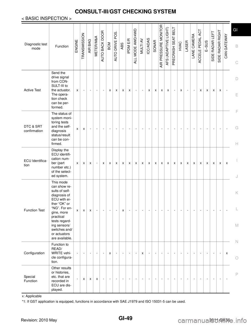
CONSULT-III/GST CHECKING SYSTEMGI-49
< BASIC INSPECTION >
C
DE
F
G H
I
J
K L
M B
GI
N
O P
x: Applicable
*1: If GST application is equipped , functions in accordance with SAE J1 979 and ISO 15031-5 can be used.
Active Test
Send the
drive signal
from CON-
SULT-III to
the actuator.
The opera-
tion check
can be per-
formed.x - - - - xxxx - - xxxx - x - - xxxx -
DTC & SRT
confirmation The status of
system moni-
toring tests
and the self-
diagnosis
status/result
can be con-
firmed.
xx----------------------
ECU Identifica-
tion Display the
ECU identifi-
cation num-
ber (part
number etc.)
of the select-
ed system.
xxx - xxxxxxxxxxxxxxxxxxxx
Function Test This mode
can show re-
sults of self-
diagnosis of
ECU with ei-
ther “OK” or
“NG”. For en-
gine, more
practical
tests regard-
ing sensors/
switches and/
or actuators
are available.xxx----x----------------
Configuration Function to
READ/
WRITE vehi-
cle configura-
tion.-----x----x------------x
Special
Function Other results
or histories,
etc. that are
recorded in
ECU are dis-
played.
-xxx--------------------
Diagnostic test
mode Function
ENGINE
TRANSMISSION AIR BAG
METER/M&A
AUTO BACK DOOR
BCM
AUTO DRIVE POS. ABS
IPDM E/R
ALL MODE AWD/4WD
MULTI AV
ICC/ADAS SONAR
AIR PRESSURE MONITOR AFS (ADAPTIVE LIGHT)
PRECRASH SEAT BELT HVAC
LASER
LANE CAMERA
ACCELE PEDAL ACT E–SUS
SIDE RADAR LEFT
SIDE RADAR RIGHT CAN GATEWAY
Revision: 2010 May2011 QX56
Page 3060 of 5598
HA-4
< PRECAUTION >
PRECAUTIONS
5. When the repair work is completed, re-connect both battery cables. With the brake pedal released, turn
the push-button ignition switch from ACC position to ON position, then to LOCK position. (The steering
wheel will lock when the push-button igniti on switch is turned to LOCK position.)
6. Perform self-diagnosis check of all control units using CONSULT-III.
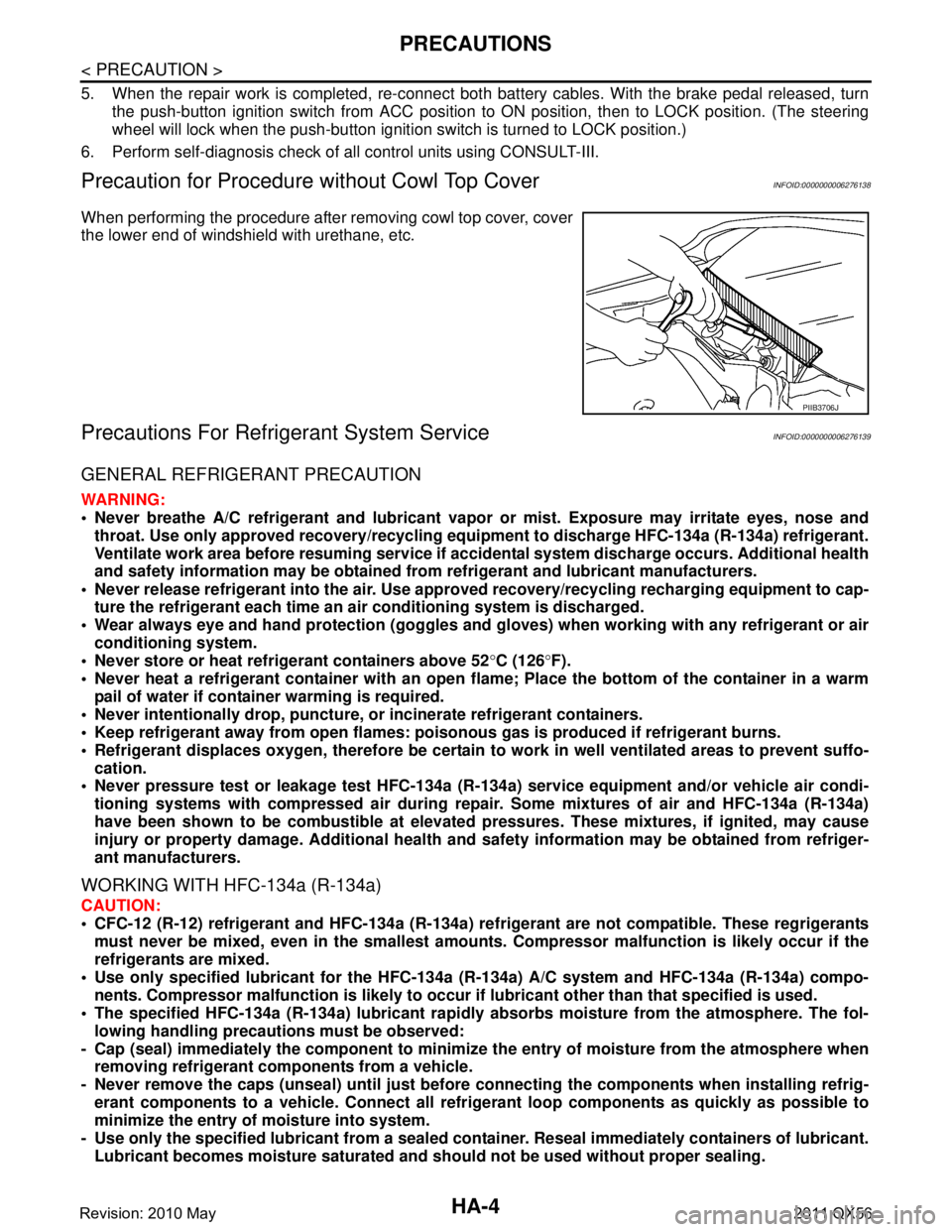
Precaution for Procedure without Cowl Top CoverINFOID:0000000006276138
When performing the procedure after removing cowl top cover, cover
the lower end of windshield with urethane, etc.
Precautions For Refrigerant System ServiceINFOID:0000000006276139
GENERAL REFRIGERANT PRECAUTION
WARNING:
Never breathe A/C refrigerant an d lubricant vapor or mist. Exposure may irritate eyes, nose and
throat. Use only approved reco very/recycling equipment to discharge HFC-134a (R-134a) refrigerant.
Ventilate work area before resuming service if acci dental system discharge occurs. Additional health
and safety information may be obtained from refrigerant and lubricant manufacturers.
Never release refrigerant into the air. Use appro ved recovery/recycling recharging equipment to cap-
ture the refrigerant each time an ai r conditioning system is discharged.
Wear always eye and hand protection (goggles and gloves) when working with any refrigerant or air
conditioning system.
Never store or heat refrigerant containers above 52 °C (126 °F).
Never heat a refrigerant container with an open flame; Place the bottom of the container in a warm
pail of water if container warming is required.
Never intentionally drop, puncture, or incinerate refrigerant containers.
Keep refrigerant away from open flames: pois onous gas is produced if refrigerant burns.
Refrigerant displaces oxygen, therefore be certain to work in well ventilated areas to prevent suffo-
cation.
Never pressure test or leakage test HFC-134a (R- 134a) service equipment and/or vehicle air condi-
tioning systems with compressed air during repair. Some mixtures of air and HFC-134a (R-134a)
have been shown to be combusti ble at elevated pressures. These mixtures, if ignited, may cause
injury or property damage. Additional health and safety information may be obtained from refriger-
ant manufacturers.
WORKING WITH HFC-134a (R-134a)
CAUTION:
CFC-12 (R-12) refrigerant and HFC-134a (R-134a) re frigerant are not compatible. These regrigerants
must never be mixed, even in the smallest amount s. Compressor malfunction is likely occur if the
refrigerants are mixed.
Use only specified lubricant for the HFC-134a (R-134a) A/C system and HFC-134a (R-134a) compo-
nents. Compressor malfunction is likely to occur if lubricant other than that specified is used.
The specified HFC-134a (R-134a) lu bricant rapidly absorbs moisture from the atmosphere. The fol-
lowing handling precauti ons must be observed:
- Cap (seal) immediately the compon ent to minimize the entry of moisture from the atmosphere when
removing refrigerant components from a vehicle.
- Never remove the caps (unseal) until just before co nnecting the components when installing refrig-
erant components to a vehicle. Connect all refr igerant loop components as quickly as possible to
minimize the entry of moisture into system.
- Use only the specified lubricant from a sealed contai ner. Reseal immediately containers of lubricant.
Lubricant becomes moisture saturated and should not be used without proper sealing.
PIIB3706J
Revision: 2010 May2011 QX56
Page 3422 of 5598
LAN-2
ITS Communication Circuit .....................................58
MAIN LINE BETWEEN ABS AND DLC CIR-
CUIT ...................................................................
60
Diagnosis Procedure ........................................... ...60
MAIN LINE BETWEEN DLC AND E-SUS CIR-
CUIT ...................................................................
61
Diagnosis Procedure ........................................... ...61
MAIN LINE BETWEEN E-SUS AND ADP CIR-
CUIT ...................................................................
62
Diagnosis Procedure ........................................... ...62
MAIN LINE BETWEEN ADP AND PWBD CIR-
CUIT ...................................................................
63
Diagnosis Procedure ........................................... ...63
MAIN LINE BETWEEN RDR-R AND RDR-L
CIRCUIT .............................................................
64
Diagnosis Procedure ........................................... ...64
MAIN LINE BETWEEN RDR-L AND LANE
CIRCUIT .............................................................
65
Diagnosis Procedure ........................................... ...65
MAIN LINE BETWEEN LANE AND APA CIR-
CUIT ...................................................................
67
Diagnosis Procedure ........................................... ...67
ECM BRANCH LINE CIRCUIT ..........................68
Diagnosis Procedure ........................................... ...68
4WD BRANCH LINE CIRCUIT ..........................69
Diagnosis Procedure ........................................... ...69
ABS BRANCH LINE CIRCUIT ..........................70
Diagnosis Procedure ........................................... ...70
TCM BRANCH LINE CIRCUIT ..........................71
Diagnosis Procedure ........................................... ...71
A-BAG BRANCH LINE CIRCUIT ......................72
Diagnosis Procedure ........................................... ...72
AFS BRANCH LINE CIRCUIT ...........................73
Diagnosis Procedure ........................................... ...73
AV BRANCH LINE CIRCUIT .............................74
Diagnosis Procedure ........................................... ...74
BCM BRANCH LINE CIRCUIT ..........................75
Diagnosis Procedure ........................................... ...75
CGW BRANCH LINE CIRCUIT (CAN COM-
MUNICATION CIRCUIT 1) .................................
76
Diagnosis Procedure ........................................... ...76
CGW BRANCH LINE CIRCUIT (CAN COM-
MUNICATION CIRCUIT 2) .................................
77
Diagnosis Procedure ........................................... ...77
DLC BRANCH LINE CIRCUIT ..........................78
Diagnosis Procedure ............................................ ...78
HVAC BRANCH LINE CIRCUIT ........................79
Diagnosis Procedure ............................................ ...79
M&A BRANCH LINE CIRCUIT ..........................80
Diagnosis Procedure ............................................ ...80
STRG BRANCH LINE CIRCUIT ........................81
Diagnosis Procedure ............................................ ...81
TPMS BRANCH LINE CIRCUIT ........................82
Diagnosis Procedure ............................................ ...82
IPDM-E BRANCH LINE CIRCUIT .....................83
Diagnosis Procedure ............................................ ...83
ADP BRANCH LINE CIRCUIT ..........................84
Diagnosis Procedure ............................................ ...84
PSB BRANCH LINE CIRCUIT ..........................85
Diagnosis Procedure ............................................ ...85
E-SUS BRANCH LINE CIRCUIT .......................86
Diagnosis Procedure ............................................ ...86
ICC BRANCH LINE CIRCUIT ............................87
Diagnosis Procedure ............................................ ...87
PWBD BRANCH LINE CIRCUIT .......................88
Diagnosis Procedure ............................................ ...88
RDR-R BRANCH LINE CIRCUIT ......................89
Diagnosis Procedure ............................................ ...89
RDR-L BRANCH LINE CIRCUIT .......................90
Diagnosis Procedure ............................................ ...90
LANE BRANCH LINE CIRCUIT ........................91
Diagnosis Procedure ............................................ ...91
APA BRANCH LINE CIRCUIT ..........................92
Diagnosis Procedure ............................................ ...92
LASER BRANCH LINE CIRCUIT ......................93
Diagnosis Procedure ............................................ ...93
CAN COMMUNICATION CIRCUIT ...................94
Diagnosis Procedure ............................................ ...94
CAN COMMUNICATION CIRCUIT 1 ................96
Diagnosis Procedure ............................................ ...96
CAN COMMUNICATION CIRCUIT 2 ................98
Diagnosis Procedure ............................................ ...98
ITS COMMUNICATION CIRCUIT .....................100
Diagnosis Procedure ............................................ .100
CAN GATEWAY
PRECAUTION ............... ............................
102
PRECAUTIONS .............................................. ..102
Revision: 2010 May2011 QX56
Page 3423 of 5598
LAN
LAN-3
C
DE
F
G H
I
J
K L
B
A
O P
N
Precaution for Supplemental Restraint System
(SRS) "AIR BAG" and "SEAT BELT PRE-TEN-
SIONER" .............................................................
..
102
SYSTEM DESCRIPTION ...........................103
COMPONENT PARTS ................................... ..103
Component Parts Location .................................. ..103
SYSTEM ...........................................................104
System Description ............................................. ..104
DIAGNOSIS SYSTEM (CAN GATEWAY) .......105
CONSULT-III Function ........................................ ..105
ECU DIAGNOSIS INFORMATION ............106
CAN GATEWAY ............................................. ..106
Reference Value ................................................. ..106
DTC Inspection Priority Chart .............................106
DTC Index ............................................................106
WIRING DIAGRAM ....................................108
CAN GATEWAY SYSTEM ............................. ..108
Wiring Diagram ................................................... ..108
BASIC INSPECTION .................................110
ADDITIONAL SERVICE WHEN REPLACING
CAN GATEWAY ............................................. ..
110
Description .......................................................... ..110
Work Procedure ....................................................110
CONFIGURATION (CAN GATEWAY) .............111
Description .......................................................... ..111
Work Procedure ....................................................111
DTC/CIRCUIT DIAGNOSIS .......................113
U1000 CAN COMM CIRCUIT ......................... ..113
Description .......................................................... ..113
DTC Logic .............................................................113
Diagnosis Procedure .............................................113
U1010 CONTROL UNIT (CAN) ........................114
Description .......................................................... ..114
DTC Logic .............................................................114
Diagnosis Procedure .............................................114
B2600 CONFIG ERROR ..................................115
Description .......................................................... ..115
DTC Logic .............................................................115
Diagnosis Procedure .............................................115
POWER SUPPLY AND GROUND CIRCUIT ....116
Diagnosis Procedure ........................................... ..116
REMOVAL AND INSTALLATION .............117
CAN GATEWAY ............................................. ..117
Removal and Installation ..................................... ..117
CAN SYSTEM (TYPE 1)
DTC/CIRCUIT DIAGNOSIS .......................
118
MAIN LINE BETWEEN ABS AND DLC CIR-
CUIT ................................................................
118
Diagnosis Procedure ........................................... ..118
MAIN LINE BETWEEN DLC AND E-SUS CIR-
CUIT ................................................................
119
Diagnosis Procedure .............................................119
MAIN LINE BETWEEN E-SUS AND ADP CIR-
CUIT ................................................................
120
Diagnosis Procedure .............................................120
ECM BRANCH LINE CIRCUIT .......................121
Diagnosis Procedure .............................................121
ABS BRANCH LINE CIRCUIT ........................122
Diagnosis Procedure .............................................122
TCM BRANCH LINE CIRCUIT ........................123
Diagnosis Procedure .............................................123
A-BAG BRANCH LINE CIRCUIT ....................124
Diagnosis Procedure .............................................124
AV BRANCH LINE CIRCUIT ..........................125
Diagnosis Procedure .............................................125
BCM BRANCH LINE CIRCUIT .......................126
Diagnosis Procedure .............................................126
DLC BRANCH LINE CIRCUIT ........................127
Diagnosis Procedure .............................................127
HVAC BRANCH LINE CIRCUIT .....................128
Diagnosis Procedure .............................................128
M&A BRANCH LINE CIRCUIT .......................129
Diagnosis Procedure .............................................129
STRG BRANCH LINE CIRCUIT .....................130
Diagnosis Procedure .............................................130
TPMS BRANCH LINE CIRCUIT .....................131
Diagnosis Procedure .............................................131
IPDM-E BRANCH LINE CIRCUIT ...................132
Diagnosis Procedure .............................................132
ADP BRANCH LINE CIRCUIT ........................133
Diagnosis Procedure .............................................133
E-SUS BRANCH LINE CIRCUIT ....................134
Diagnosis Procedure .............................................134
PWBD BRANCH LINE CIRCUIT ....................135
Diagnosis Procedure .............................................135
CAN COMMUNICATION CIRCUIT .................136
Diagnosis Procedure .............................................136
Revision: 2010 May2011 QX56