Page 5457 of 5598

COMPONENT PARTSWT-7
< SYSTEM DESCRIPTION >
C
DF
G H
I
J
K L
M A
B
WT
N
O P
Component DescriptionINFOID:0000000006225489
*: Mainly used for the tire inflation function.
Low Tire Pressure Warning Control UnitINFOID:0000000006225490
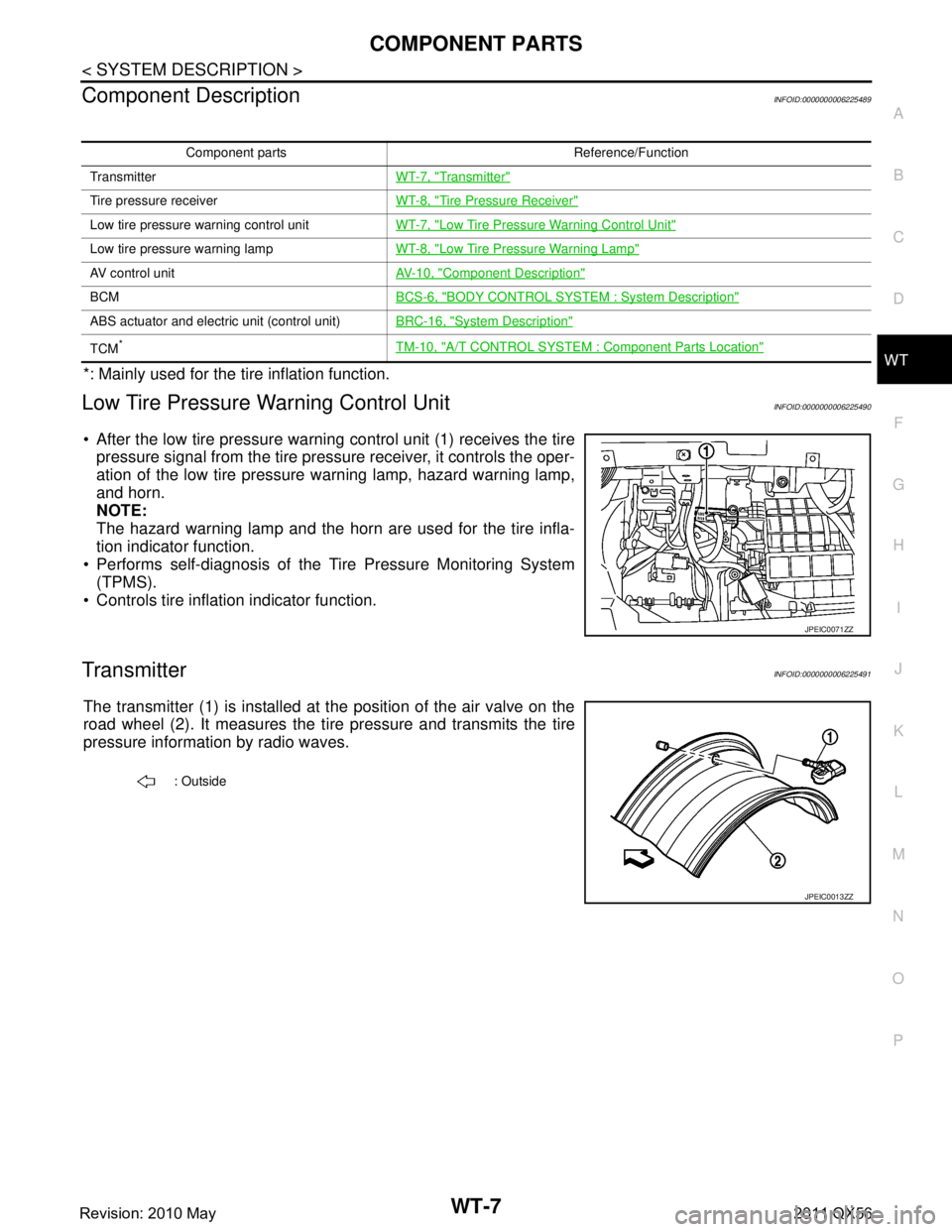
After the low tire pressure warning control unit (1) receives the tire pressure signal from the tire pressure receiver, it controls the oper-
ation of the low tire pressure warning lamp, hazard warning lamp,
and horn.
NOTE:
The hazard warning lamp and the horn are used for the tire infla-
tion indicator function.
Performs self-diagnosis of the Tire Pressure Monitoring System
(TPMS).
Controls tire inflation indicator function.
TransmitterINFOID:0000000006225491
The transmitter (1) is installed at the position of the air valve on the
road wheel (2). It measures the ti re pressure and transmits the tire
pressure information by radio waves.
Component parts Reference/Function
Transmitter WT-7, "
Transmitter"
Tire pressure receiverWT-8, "Tire Pressure Receiver"
Low tire pressure warning control unit WT-7, "Low Tire Pressure Warning Control Unit"
Low tire pressure warning lamp WT-8, "Low Tire Pressure Warning Lamp"
AV control unit AV- 1 0 , "Component Description"
BCMBCS-6, "BODY CONTROL SYSTEM : System Description"
ABS actuator and electric unit (control unit)BRC-16, "System Description"
TCM*TM-10, "A/T CONTROL SYSTEM : Component Parts Location"
JPEIC0071ZZ
: Outside
JPEIC0013ZZ
Revision: 2010 May2011 QX56
Page 5460 of 5598

WT-10
< SYSTEM DESCRIPTION >
SYSTEM
*: Mainly used for the tire inflation indicator function.
LOW TIRE PRESSURE WARNING LAMP CONTROL CONDITION
Uses CAN communication from the low tire pressure warning control unit to illuminate the low tire pressure
warning lamp on the combination meter.
*: Tire pressure at each condition differs.
HAZARD WARNING LAMP CONTROL CONDITION
The low tire pressure warning control unit transmits a hazard request signal to BCM. BCM blinks the hazard
warning lamp, according to the signal.
The hazard warning lamp blinks under the following conditions.
Condition of Blinking The Hazard Warning Lamp When wake-up of registered wheel has been completed. Refer to WT-28, "Work Procedure".
When ID registration is completed. Refer to WT-29, "
Work Procedure".
During the use of the tire inflation indicator function.
HORN CONTROL CONDITION
The low tire pressure warning control unit transmits a horn request signal to BCM. BCM controls horn sound,
according to the signal.
The horn sounds under the following condition.
Condition of Sounding Horn During the use of tire inflation indicator function.
Tire Inflation Indicator FunctionINFOID:0000000006225495
This function operates only when the A/T shift selector position is in P-range with the ignition switch ON or
with the engine started.
NOTE:
The tire inflation indicator function is recommended to use with the engine stopped.
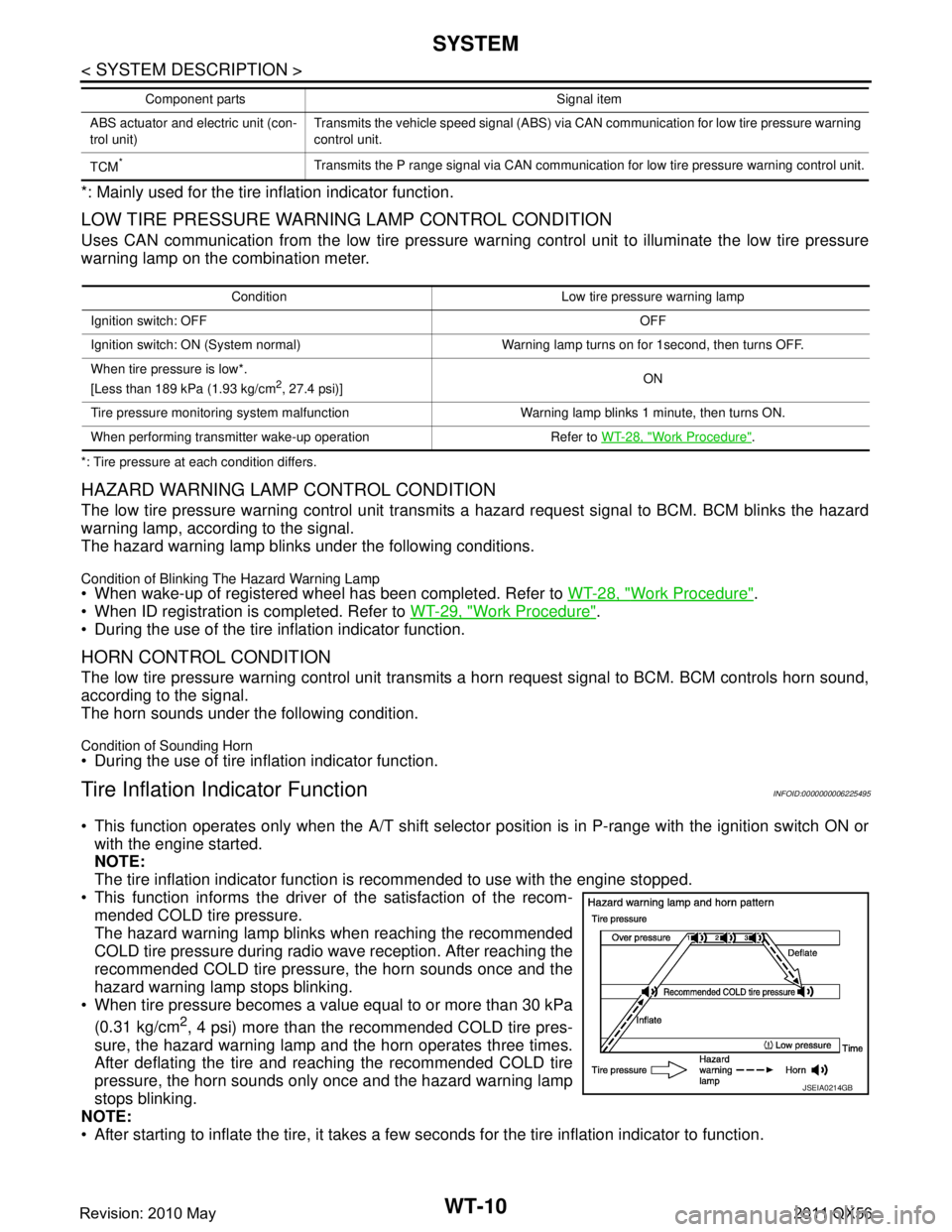
This function informs the driver of the satisfaction of the recom- mended COLD tire pressure.
The hazard warning lamp blinks when reaching the recommended
COLD tire pressure during radio wave reception. After reaching the
recommended COLD tire pressure, the horn sounds once and the
hazard warning lamp stops blinking.
When tire pressure becomes a value equal to or more than 30 kPa
(0.31 kg/cm
2, 4 psi) more than the recommended COLD tire pres-
sure, the hazard warning lamp and the horn operates three times.
After deflating the tire and reaching the recommended COLD tire
pressure, the horn sounds only once and the hazard warning lamp
stops blinking.
NOTE:
After starting to inflate the tire, it takes a few seconds for the tire inflation indicator to function.
ABS actuator and electric unit (con-
trol unit) Transmits the vehicle speed signal (ABS) via CAN communication for low tire pressure warning
control unit.
TCM
*Transmits the P range signal via CAN communication for low tire pressure warning control unit.
Component parts Signal item
Condition Low tire pr
essure warning lamp
Ignition switch: OFF OFF
Ignition switch: ON (System normal) Warning lamp turns on for 1second, then turns OFF.
When tire pressure is low*.
[Less than 189 kPa (1.93 kg/cm
2, 27.4 psi)] ON
Tire pressure monitoring system malfunction Warning lamp blinks 1 minute, then turns ON.
When performing transmitter wake-up operation Refer to WT-28, "
Work Procedure".
JSEIA0214GB
Revision: 2010 May2011 QX56
Page 5491 of 5598

C1729 VEHICLE SPEED SIGNALWT-41
< DTC/CIRCUIT DIAGNOSIS >
C
DF
G H
I
J
K L
M A
B
WT
N
O P
C1729 VEHICLE SPEED SIGNAL
DTC LogicINFOID:0000000006225516
DTC DETECTION LOGIC
DTC CONFIRMATION PROCEDURE
1.DTC CONFIRMATION PROCEDURE
With CONSULT-III
1. Drive for 3 minutes at a speed of 40 km/h (25 MPH) or more without stopping.
2. Stop the vehicle.
3. Perform self-diagnosis for “AIR PRESSURE MONITOR”.
Is DTC
“C1729” detected?
YES >> Proceed to WT-41, "Diagnosis Procedure".
NO >> INSPECTION END
Diagnosis ProcedureINFOID:0000000006225517
1.PERFORM ABS ACTUATOR AND ELECTRIC UNIT (CONTROL UNIT) SELF-DIAGNOSIS
With CONSULT-III
Perform self-diagnosis for “ABS”.
Is any DTC detected?
YES >> Check malfunctioning circuit.
NO >> GO TO 2.
2.PERFORM SELF-DIAGNOSIS AGAIN
With CONSULT-III
Perform “DTC CONFIRMATION PROCEDURE” (self-diagnosis) again. Refer to WT-41, "
DTC Logic".
Is DTC
“C1729” detected?
YES >> Replace the low tire pressure warning control unit. Refer to WT-65, "Removal and Installation".
NO >> GO TO 3.
3.CHECK LOW TIRE PRESSURE WARNING CONTROL UNIT INPUT/OUTPUT SIGNAL
Check the low tire pressure warning control unit input/output signal values. Refer to WT-14, "
Reference
Va l u e".
Is the inspection result normal?
YES >> Check pin terminal and connection of each harness connector for malfunctioning conditions.
NO >> Replace the low tire pressure warning control unit. Refer to WT-65, "
Removal and Installation".
DTC Display Item Malfunction detected condition Possible causes
C1729 VHCL SPEED SIG ERR Vehicle speed signal not detected. CAN communication malfunction
Low tire pressure warning control
unit malfunction
ABS actuator and electric unit (control unit) malfunction
Revision: 2010 May2011 QX56