2011 INFINITI QX56 ABS
[x] Cancel search: ABSPage 2549 of 5598
![INFINITI QX56 2011 Factory Service Manual
ENGINE CONTROL SYSTEM SYMPTOMSEC-525
< SYMPTOM DIAGNOSIS > [VK56VD]
C
D
E
F
G H
I
J
K L
M A
EC
NP
O
Mass air flow sensor circuit
1
12 2
222 2 EC-201
Engine coolant temperature sensor circuit
333
EC-2 INFINITI QX56 2011 Factory Service Manual
ENGINE CONTROL SYSTEM SYMPTOMSEC-525
< SYMPTOM DIAGNOSIS > [VK56VD]
C
D
E
F
G H
I
J
K L
M A
EC
NP
O
Mass air flow sensor circuit
1
12 2
222 2 EC-201
Engine coolant temperature sensor circuit
333
EC-2](/manual-img/42/57033/w960_57033-2548.png)
ENGINE CONTROL SYSTEM SYMPTOMSEC-525
< SYMPTOM DIAGNOSIS > [VK56VD]
C
D
E
F
G H
I
J
K L
M A
EC
NP
O
Mass air flow sensor circuit
1
12 2
222 2 EC-201
Engine coolant temperature sensor circuit
333
EC-217
Air fuel ratio (A/F) sensor 1 circuit EC-181
EC-228
EC-232
EC-235
EC-238
Throttle position sensor circuit
22EC-219
EC-288
EC-406
EC-407
EC-475
Accelerator pedal position sensor circuit 3 2 1
EC-468EC-471
EC-478
Knock sensor circuit 2 3
EC-297
Engine oil temperature sensor 4 2 3EC-285
Crankshaft position sensor circuit 2 2EC-299
Camshaft position sensor circuit 3 2EC-303
Vehicle speed signal circuit 2 3 3 3EC-356
Power steering pressure sensor circuit 2 3 3EC-371
ECM 22333333333EC-376EC-378
EC-380
Intake valve timing control solenoid valve cir-
cuit
32 13223 3
EC-193
VVEL control module 3 4 4 3 EC-451EC-452
VVEL actuator motor 3 4 4 3
EC-390
VVEL actuator motor relay 3 4 4 3EC-393
VVEL control shaft position sensor 3 4 4 3EC-387
PNP signal circuit 3 3 3 3 3EC-383
Refrigerant pressure sensor circuit 2 3 3 4EC-520
Electrical load signal circuit 3EC-493
Air conditioner circuit 223333333 3 2HAC-60
ABS actuator and electric unit (control unit) 4BRC-60
SYMPTOM
Reference
page
HARD/NO START/RESTART (EXCP. HA)
ENGINE STALL
HESITATION/SURGING/FLAT SPOT
SPARK KNOCK/DETONATION
LACK OF POWER/POOR ACCELERATION
HIGH IDLE/LOW IDLE
ROUGH IDLE/HUNTING
IDLING VIBRATION
SLOW/NO RETURN TO IDLE
OVERHEATS/WATER TEMPERATURE HIGH
EXCESSIVE FUEL CONSUMPTION
EXCESSIVE OIL CONSUMPTION
BATTERY DEAD (UNDER CHARGE)
Warranty symptom code AA AB AC AD AE AF AG AH AJ AK AL AM HA
Revision: 2010 May2011 QX56
Page 2550 of 5598
![INFINITI QX56 2011 Factory Service Manual
EC-526
< SYMPTOM DIAGNOSIS >[VK56VD]
ENGINE CONTROL SYSTEM SYMPTOMS
1 - 6: The numbers refer to the order of inspection.
(continued on next page)
SYSTEM — ENGINE MECHANICAL & OTHER
Manifold absolut INFINITI QX56 2011 Factory Service Manual
EC-526
< SYMPTOM DIAGNOSIS >[VK56VD]
ENGINE CONTROL SYSTEM SYMPTOMS
1 - 6: The numbers refer to the order of inspection.
(continued on next page)
SYSTEM — ENGINE MECHANICAL & OTHER
Manifold absolut](/manual-img/42/57033/w960_57033-2549.png)
EC-526
< SYMPTOM DIAGNOSIS >[VK56VD]
ENGINE CONTROL SYSTEM SYMPTOMS
1 - 6: The numbers refer to the order of inspection.
(continued on next page)
SYSTEM — ENGINE MECHANICAL & OTHER
Manifold absolute pressure sensor circuit 3
EC-210
Battery current sensor 4 5 5 3EC-412EC-420
EC-424
Heated oxygen sensor 2 6 6 6 6 5EC-243EC-249
EC-257
SYMPTOM
Reference
page
HARD/NO START/RESTART (EXCP. HA)
ENGINE STALL
HESITATION/SURGING/FLAT SPOT
SPARK KNOCK/DETONATION
LACK OF POWER/POOR ACCELERATION
HIGH IDLE/LOW IDLE
ROUGH IDLE/HUNTING
IDLING VIBRATION
SLOW/NO RETURN TO IDLE
OVERHEATS/WATER TEMPERATURE HIGH
EXCESSIVE FUEL CONSUMPTION
EXCESSIVE OIL CONSUMPTION
BATTERY DEAD (UNDER CHARGE)
Warranty symptom code AA AB AC AD AE AF AG AH AJ AK AL AM HA
Fuel Fuel tank 5
5 FL-4
Fuel piping 555 55 5
FL-4
Vapor lock —
Valve deposit 5 555 55 5 —
Poor fuel (Heavy weight gasoline,
Low octane) —
Revision: 2010 May2011 QX56
Page 2592 of 5598

EM-30
< REMOVAL AND INSTALLATION >
INTAKE MANIFOLD
INTAKE MANIFOLD
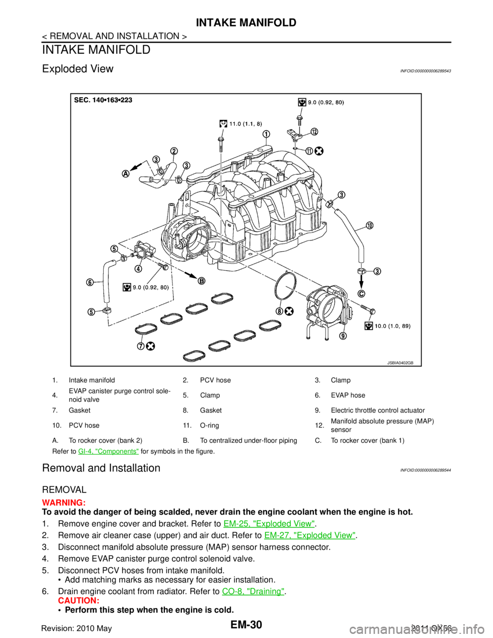
Exploded ViewINFOID:0000000006289543
Removal and InstallationINFOID:0000000006289544
REMOVAL
WARNING:
To avoid the danger of being scalded, never drain the engine coolant when the engine is hot.
1. Remove engine cover and bracket. Refer to EM-25, "
Exploded View".
2. Remove air cleaner case (upper) and air duct. Refer to EM-27, "
Exploded View".
3. Disconnect manifold absolute pressu re (MAP) sensor harness connector.
4. Remove EVAP canister purge control solenoid valve.
5. Disconnect PCV hoses from intake manifold. Add matching marks as necessary for easier installation.
6. Drain engine coolant from radiator. Refer to CO-8, "
Draining".
CAUTION:
Perform this step when the engine is cold.
1. Intake manifold 2. PCV hose 3. Clamp
4. EVAP canister purge control sole-
noid valve 5. Clamp 6. EVAP hose
7. Gasket 8. Gasket 9. Electric throttle control actuator
10. PCV hose 11. O-ring 12. Manifold absolute pressure (MAP)
sensor
A. To rocker cover (bank 2) B. To centralized under-floor piping C. To rocker cover (bank 1)
Refer to GI-4, "
Components" for symbols in the figure.
JSBIA0402GB
Revision: 2010 May2011 QX56
Page 2593 of 5598

INTAKE MANIFOLDEM-31
< REMOVAL AND INSTALLATION >
C
DE
F
G H
I
J
K L
M A
EM
NP
O
Never spill engine coolant on drive belts.
NOTE:
When removing only intake manifold, move electric
throttle control actuator without disconnecting the
water hoses.
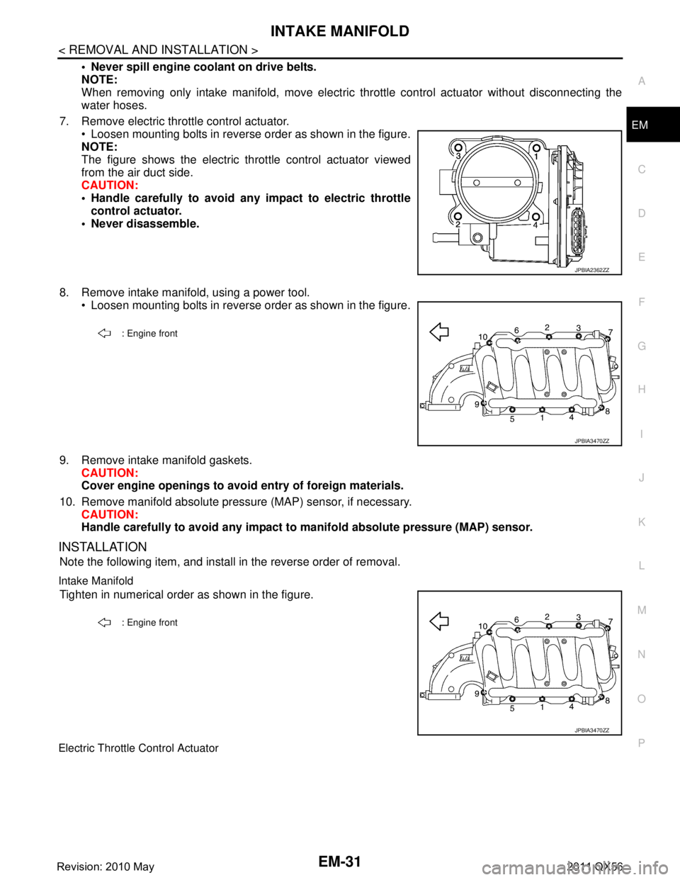
7. Remove electric throttle control actuator. Loosen mounting bolts in reverse order as shown in the figure.
NOTE:
The figure shows the electric throttle control actuator viewed
from the air duct side.
CAUTION:
Handle carefully to avoid an y impact to electric throttle
control actuator.
Never disassemble.
8. Remove intake manifold, using a power tool. Loosen mounting bolts in reverse order as shown in the figure.
9. Remove intake manifold gaskets. CAUTION:
Cover engine openings to avoid entry of foreign materials.
10. Remove manifold absolute pressure (MAP) sensor, if necessary. CAUTION:
Handle carefully to avoid any impact to manifold absolute pressure (MAP) sensor.
INSTALLATION
Note the following item, and install in the reverse order of removal.
Intake Manifold
Tighten in numerical order as shown in the figure.
Electric Throttle Control Actuator
JPBIA2362ZZ
: Engine front
JPBIA3470ZZ
: Engine front
JPBIA3470ZZ
Revision: 2010 May2011 QX56
Page 2742 of 5598
![INFINITI QX56 2011 Factory Service Manual
EXL-32
< SYSTEM DESCRIPTION >[XENON TYPE]
DIAGNOSIS SYSTEM (AFS)
DIAGNOSIS SYSTEM (AFS)
CONSULT-III Function (ADAPTIVE LIGHT)INFOID:0000000006213915
APPLICATION ITEM
WORK SUPPORT
*: Adjusts the steer INFINITI QX56 2011 Factory Service Manual
EXL-32
< SYSTEM DESCRIPTION >[XENON TYPE]
DIAGNOSIS SYSTEM (AFS)
DIAGNOSIS SYSTEM (AFS)
CONSULT-III Function (ADAPTIVE LIGHT)INFOID:0000000006213915
APPLICATION ITEM
WORK SUPPORT
*: Adjusts the steer](/manual-img/42/57033/w960_57033-2741.png)
EXL-32
< SYSTEM DESCRIPTION >[XENON TYPE]
DIAGNOSIS SYSTEM (AFS)
DIAGNOSIS SYSTEM (AFS)
CONSULT-III Function (ADAPTIVE LIGHT)INFOID:0000000006213915
APPLICATION ITEM
WORK SUPPORT
*: Adjusts the steering angle sensor neutral position on ABS actuator and electrical unit (control unit) side. Refer to
BRC-64, "Work Pro-
cedure".
DATA MONITOR
*: The swivel angle "0°" (feedback value) of the swivel position sensor signal may differ from the swivel angle "0 °" of the swivel motor
(AFS control unit command value). This causes that the swivel motor initializes the value based on the step number from the sto pper.
ACTIVE TEST
Diagnostic mode Description
Ecu Identification Allows confirmation of AFS control unit part number.
Self Diagnostic Result Displays the diagnosis results judged by AFS control unit.
Work support Sets each sensor.
Data monitor Indicates AFS control unit input data in real time.
Active test Provides the drive signal to the load. Checks operation.
Service item Description
ST ANG SEN ADJUSTMENT
*—
LEVELIZER ADJUSTMENT Adjusts the height sensor signal output value (AFS control unit recognized) in the un-
loaded vehicle condition.
Monitor item
[Unit] Description
STR ANGLS SIG
[deg] The steering angle value judged by the steering angle sensor signal received from
the steering angle sensor via CAN communication
VHCL SPD
[km/h] The vehicle speed signal value from the combination meter via CAN communication
SLCT LVR POSI
[P/R/N/D/M/FF] The selector lever status judged by the position indicator signal received from TCM
via CAN communication
HEAD LAMP
[On/Off] The headlamp On/Off status judged by the low beam headlamp (ON) signal received
from IPDM E/R via
CAN communication
AFS SW
[On/Off] The AFS On/Off status judged by AFS control unit
HI SEN OTP RR
[V] The rear height sensor signal voltage value input from the rear height sensor
HI SEN OTP FR
[V] The front height sensor signal voltage value input from the front height sensor
LEV ACTR VLTG
[%] The ratio value to the battery voltage generated by the levelizer activation signal con-
trol value judged by AFS control unit
SWVL SEN RH
*
[deg] The head lamp swivel angle value judged by AFS control unit received from the swiv-
el position sensor signal input from the swivel actuator
SWVL SEN LH
*
[deg]
SWVL ANGLE RH
*
[deg]
The swivel angle command value to the swivel motor judged by AFS control unit
SWVL ANGLE LH
*
[deg]
Revision: 2010 May2011 QX56
Page 2790 of 5598
![INFINITI QX56 2011 Factory Service Manual
EXL-80
< DTC/CIRCUIT DIAGNOSIS >[XENON TYPE]
C0126 STEERING ANGLE SENSOR SIGNAL
C0126 STEERING ANGLE SENSOR SIGNAL
DTC LogicINFOID:0000000006213944
DTC DETECTION LOGIC
DTC CONFIRMATION PROCEDURE
1.DT INFINITI QX56 2011 Factory Service Manual
EXL-80
< DTC/CIRCUIT DIAGNOSIS >[XENON TYPE]
C0126 STEERING ANGLE SENSOR SIGNAL
C0126 STEERING ANGLE SENSOR SIGNAL
DTC LogicINFOID:0000000006213944
DTC DETECTION LOGIC
DTC CONFIRMATION PROCEDURE
1.DT](/manual-img/42/57033/w960_57033-2789.png)
EXL-80
< DTC/CIRCUIT DIAGNOSIS >[XENON TYPE]
C0126 STEERING ANGLE SENSOR SIGNAL
C0126 STEERING ANGLE SENSOR SIGNAL
DTC LogicINFOID:0000000006213944
DTC DETECTION LOGIC
DTC CONFIRMATION PROCEDURE
1.DTC ERASE
Erase the DTC memory of AFS with CONSULT-III.
>> GO TO 2.
2.DTC CONFIRMATION
1. Start the engine.
2. Turn the steering wheel to the maximum right/left.
3. Select the self-diagnosis with CONSULT-III.
4. Check the self-diagnosis result. Refer to EXL-39, "
DTC Index".
Is DTC
“C0126” detected?
YES >> Refer to EXL-80, "Diagnosis Procedure".
NO >> Refer to GI-40, "
Intermittent Incident".
Diagnosis ProcedureINFOID:0000000006213945
1.ABS ACTUATOR AND ELECTRICAL UNIT (CONTROL UNIT) SELF-DIAGNOSIS
Check the self-diagnosis result with CONSULT-III. C heck that ABS actuator and electrical unit (control unit)
does not detect any DTCs.
Is any DTC detected?
YES >> Check ABS actuator and electrical unit (control unit).Refer to BRC-51, "DTC Index".
NO >> GO TO 2.
2.DTC ERASE
Erase DTC memory of AFS with CONSULT-III.
Is the memory erased?
YES >> Inspection end.
NO >> Replace AFS control unit. Refer to EXL-135, "
Removal and Installation"
DTC No. Trouble diagnosis name DTC detection condition Possible causes
C0126 Steering angle sensor signal In any of the following conditions
The steering angle sensor signal
is not received.
The steering angle sensor signal error is received.
Out-of-standard signal (-900 °-
+900 °) is received. Steering angle sensor
AFS control unit
Revision: 2010 May2011 QX56
Page 2868 of 5598

FRONT BUMPEREXT-13
< REMOVAL AND INSTALLATION >
C
DE
F
G H
I
J
L
M A
B
EXT
N
O P
Removal and InstallationINFOID:0000000006367598
REMOVAL
CAUTION:
Bumper fascia is made of resin. Never apply strong force to it, and be careful to prevent contact with
oil.
1. Fully open hood assembly.
2. Remove front grille. Refer to EXT-19, "
Removal and Installation".
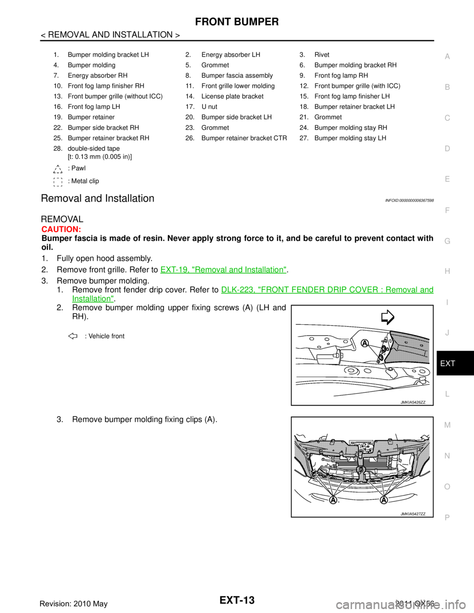
3. Remove bumper molding. 1. Remove front fender drip cover. Refer to DLK-223, "
FRONT FENDER DRIP COVER : Removal and
Installation".
2. Remove bumper molding upper fixing screws (A) (LH and
RH).
3. Remove bumper molding fixing clips (A).
1. Bumper molding bracket LH 2. Energy absorber LH 3. Rivet
4. Bumper molding 5. Grommet 6. Bumper molding bracket RH
7. Energy absorber RH 8. Bumper fascia assembly 9. Front fog lamp RH
10. Front fog lamp finisher RH 11. Front grille lower molding 12. Front bumper grille (with ICC)
13. Front bumper grille (without ICC) 14. License plate bracket 15. Front fog lamp finisher LH
16. Front fog lamp LH 17. U nut 18. Bumper retainer bracket LH
19. Bumper retainer 20. Bumper side bracket LH 21. Grommet
22. Bumper side bracket RH 23. Grommet 24. Bumper molding stay RH
25. Bumper retainer bracket RH 26. Bumper retainer bracket CTR 27. Bumper molding stay LH
28. double-sided tape [t: 0.13 mm (0.005 in)]
: Pawl
: Metal clip
: Vehicle front
JMKIA5426ZZ
JMKIA5427ZZ
Revision: 2010 May2011 QX56
Page 2872 of 5598

REAR BUMPEREXT-17
< REMOVAL AND INSTALLATION >
C
DE
F
G H
I
J
L
M A
B
EXT
N
O P
Removal and InstallationINFOID:0000000006367600
REMOVAL
CAUTION:
Bumper fascia is made of resin. Never apply strong force to it, and be careful to prevent contact with
oil.
1. Fully open back door assembly.
2. Remove rear combination lamp (LH and RH). Refer to EXL-138, "
Removal and Installation".
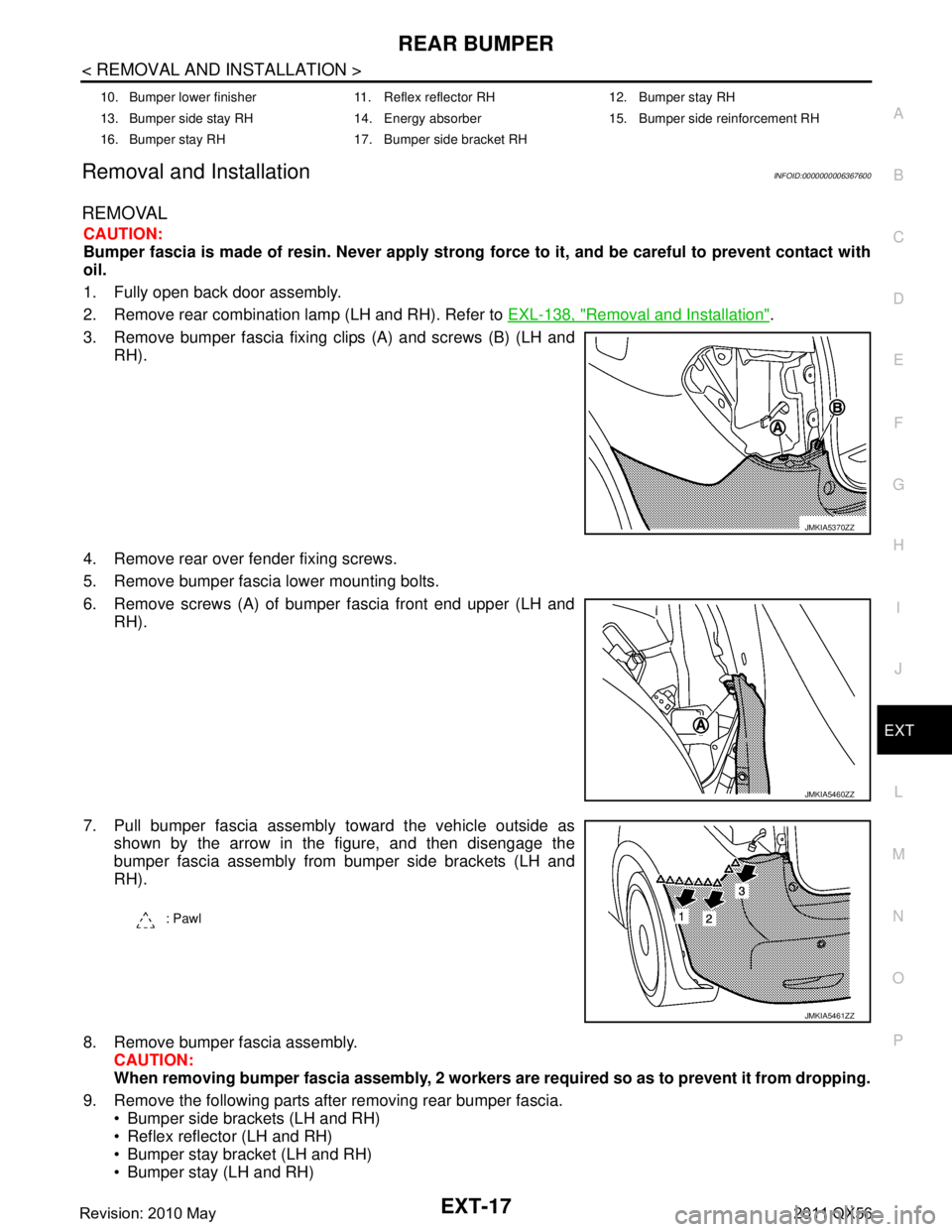
3. Remove bumper fascia fixing clips (A) and screws (B) (LH and RH).
4. Remove rear over fender fixing screws.
5. Remove bumper fascia lower mounting bolts.
6. Remove screws (A) of bumper fascia front end upper (LH and RH).
7. Pull bumper fascia assembly toward the vehicle outside as shown by the arrow in the figure, and then disengage the
bumper fascia assembly from bumper side brackets (LH and
RH).
8. Remove bumper fascia assembly. CAUTION:
When removing bumper fascia assembly, 2 workers ar e required so as to prevent it from dropping.
9. Remove the following parts after removing rear bumper fascia. Bumper side brackets (LH and RH)
Reflex reflector (LH and RH)
Bumper stay bracket (LH and RH)
Bumper stay (LH and RH)
10. Bumper lower finisher 11. Reflex reflector RH 12. Bumper stay RH
13. Bumper side stay RH 14. Energy absorber 15. Bumper side reinforcement RH
16. Bumper stay RH 17. Bumper side bracket RH
JMKIA5370ZZ
JMKIA5460ZZ
: Pawl
JMKIA5461ZZ
Revision: 2010 May2011 QX56