2011 INFINITI QX56 oil
[x] Cancel search: oilPage 2992 of 5598
GI-28
< PRECAUTION >
PRECAUTIONS
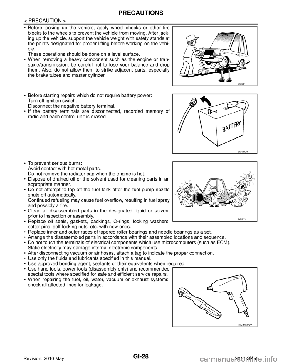
Before jacking up the vehicle, apply wheel chocks or other tireblocks to the wheels to prevent t he vehicle from moving. After jack-
ing up the vehicle, support the vehicle weight with safety stands at
the points designated for proper lifting before working on the vehi-
cle.
These operations should be done on a level surface.
When removing a heavy component such as the engine or tran- saxle/transmission, be careful not to lose your balance and drop
them. Also, do not allow them to strike adjacent parts, especially
the brake tubes and master cylinder.
Before starting repairs which do not require battery power: Turn off ignition switch.
Disconnect the negative battery terminal.
If the battery terminals are disconnected, recorded memory of
radio and each control unit is erased.
To prevent serious burns: Avoid contact with hot metal parts.
Do not remove the radiator cap when the engine is hot.
Dispose of drained oil or the solvent used for cleaning parts in an appropriate manner.
Do not attempt to top off the fuel tank after the fuel pump nozzle
shuts off automatically.
Continued refueling may cause fuel overflow, resulting in fuel spray
and possibly a fire.
Clean all disassembled parts in the designated liquid or solvent prior to inspection or assembly.
Replace oil seals, gaskets, packings, O-rings, locking washers,
cotter pins, self-locking nuts, etc. with new ones.
Replace inner and outer races of tapered roller bearings and needle bearings as a set.
Arrange the disassembled parts in accordance with their assembled locations and sequence.
Do not touch the terminals of electrical com ponents which use microcomputers (such as ECM).
Static electricity may damage internal electronic components.
After disconnecting vacuum or air hoses, atta ch a tag to indicate the proper connection.
Use only the fluids and lubricants specified in this manual.
Use approved bonding agent, sealants or their equivalents when required.
Use hand tools, power tools (disassembly only) and recommended special tools where specified for safe and efficient service repairs.
When repairing the fuel, oil, water, vacuum or exhaust systems, check all affected lines for leakage.
SGI231
SEF289H
SGI233
JPAIA0335ZZ
Revision: 2010 May2011 QX56
Page 2994 of 5598
GI-30
< PRECAUTION >
PRECAUTIONS
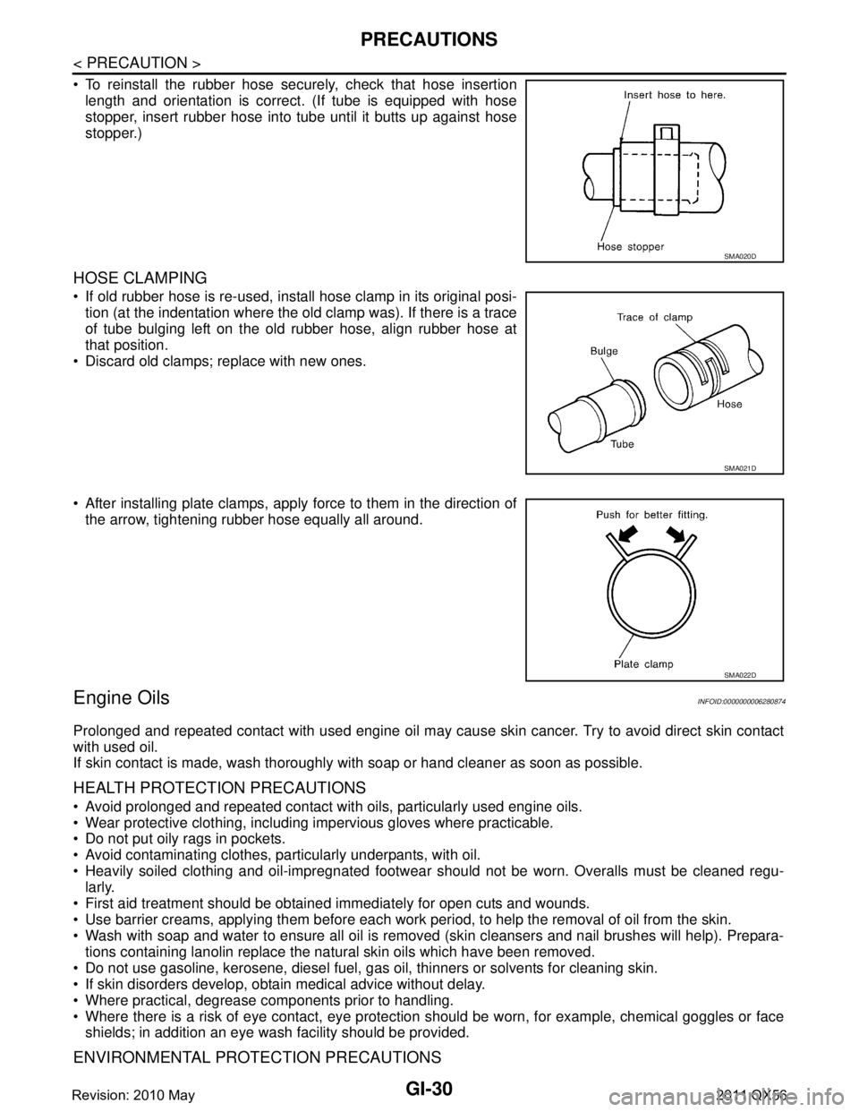
To reinstall the rubber hose securely, check that hose insertionlength and orientation is correct. (If tube is equipped with hose
stopper, insert rubber hose into tube until it butts up against hose
stopper.)
HOSE CLAMPING
If old rubber hose is re-used, install hose clamp in its original posi-tion (at the indentation where the old clamp was). If there is a trace
of tube bulging left on the old rubber hose, align rubber hose at
that position.
Discard old clamps; replace with new ones.
After installing plate clamps, apply force to them in the direction of the arrow, tightening rubber hose equally all around.
Engine OilsINFOID:0000000006280874
Prolonged and repeated contact with used engine oil may cause skin cancer. Try to avoid direct skin contact
with used oil.
If skin contact is made, wash thoroughly with soap or hand cleaner as soon as possible.
HEALTH PROTECTION PRECAUTIONS
Avoid prolonged and repeated contact with oils, particularly used engine oils.
Wear protective clothing, including impervious gloves where practicable.
Do not put oily rags in pockets.
Avoid contaminating clothes, pa rticularly underpants, with oil.
Heavily soiled clothing and oil-impregnated footwear should not be worn. Overalls must be cleaned regu-
larly.
First aid treatment should be obtained immediately for open cuts and wounds.
Use barrier creams, applying them before each work period, to help the removal of oil from the skin.
Wash with soap and water to ensure all oil is removed (skin cleansers and nail brushes will help). Prepara-
tions containing lanolin replace the natural skin oils which have been removed.
Do not use gasoline, kerosene, diesel fuel, gas oil, thinners or solvents for cleaning skin.
If skin disorders develop, obtain medical advice without delay.
Where practical, degrease components prior to handling.
Where there is a risk of eye contact, eye protection should be worn, for example, chemical goggles or face
shields; in addition an eye wash facility should be provided.
ENVIRONMENTAL PROTECTION PRECAUTIONS
SMA020D
SMA021D
SMA022D
Revision: 2010 May2011 QX56
Page 2995 of 5598
PRECAUTIONSGI-31
< PRECAUTION >
C
DE
F
G H
I
J
K L
M B
GI
N
O P
Dispose of used oil and used oil filters through authorized waste disposal contractors to licensed waste dis-
posal sites, or to the waste oil reclamation trade. If in doubt, contact the local authority for advice on disposal
facilities.
It is illegal to pour used oil on to the ground, dow n sewers or drains, or into water sources.
The regulations concerning po llution vary between regions.
Air ConditioningINFOID:0000000006280875
Use an approved refrigerant recovery unit any time t he air conditioning system must be discharged. Refer to
HA section “REFRIGERANT” fo r specific instructions.
FuelINFOID:0000000006280876
INFINITI recommends the use of unleaded premium gasoli ne with an octane rating of at least 91 AKI (Anti-
Knock Index) number (Research octane number 96).
If unleaded premium gasoline is not available, unleaded r egular gasoline with an octane rating of at least 87
AKI number (Research octane number 91), can be used. In such case, engine performance may be decrease.
CAUTION:
Using a fuel other than that specified could ad versely affect the emission control system, and may
also affect warranty coverage.
Under no circumstances should a leaded gasoline be used, because this will damage the three-way
catalyst.
Do not use E-85 fuel in the vehicle . The vehicle is not designed to run on E-85 fuel. Using E-85 fuel
can damage the fuel system components and is not covered by the INFINITI vehicle limited warranty.
Revision: 2010 May2011 QX56
Page 3001 of 5598
SERVICE INFORMATION FOR ELECTRICAL INCIDENTGI-37
< BASIC INSPECTION >
C
DE
F
G H
I
J
K L
M B
GI
N
O P
Do not apply excessive shock to the control unit by dropping or hit- ting it.
Be careful to prevent condensation in the control unit due to rapid
temperature changes and do not let water or rain get on it. If water
is found in the control unit, dry it fully and then install it in the vehi-
cle.
Be careful not to let oil to get on the control unit connector.
Avoid cleaning the control unit with volatile oil.
Do not disassemble the contro l unit, and do not remove the upper
and lower covers.
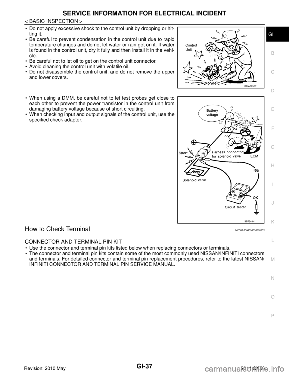
When using a DMM, be careful not to let test probes get close to each other to prevent the power transistor in the control unit from
damaging battery voltage because of short circuiting.
When checking input and output signals of the control unit, use the
specified check adapter.
How to Check TerminalINFOID:0000000006280853
CONNECTOR AND TERMINAL PIN KIT
Use the connector and terminal pin kits listed below when replacing connectors or terminals.
The connector and terminal pin kits contain some of the most commonly used NISSAN/INFINITI connectors
and terminals. For detailed connector and terminal pin r eplacement procedures, refer to the latest NISSAN/
INFINITI CONNECTOR AND TERMINAL PIN SERVICE MANUAL.
SAIA0255E
SEF348N
Revision: 2010 May2011 QX56
Page 3029 of 5598
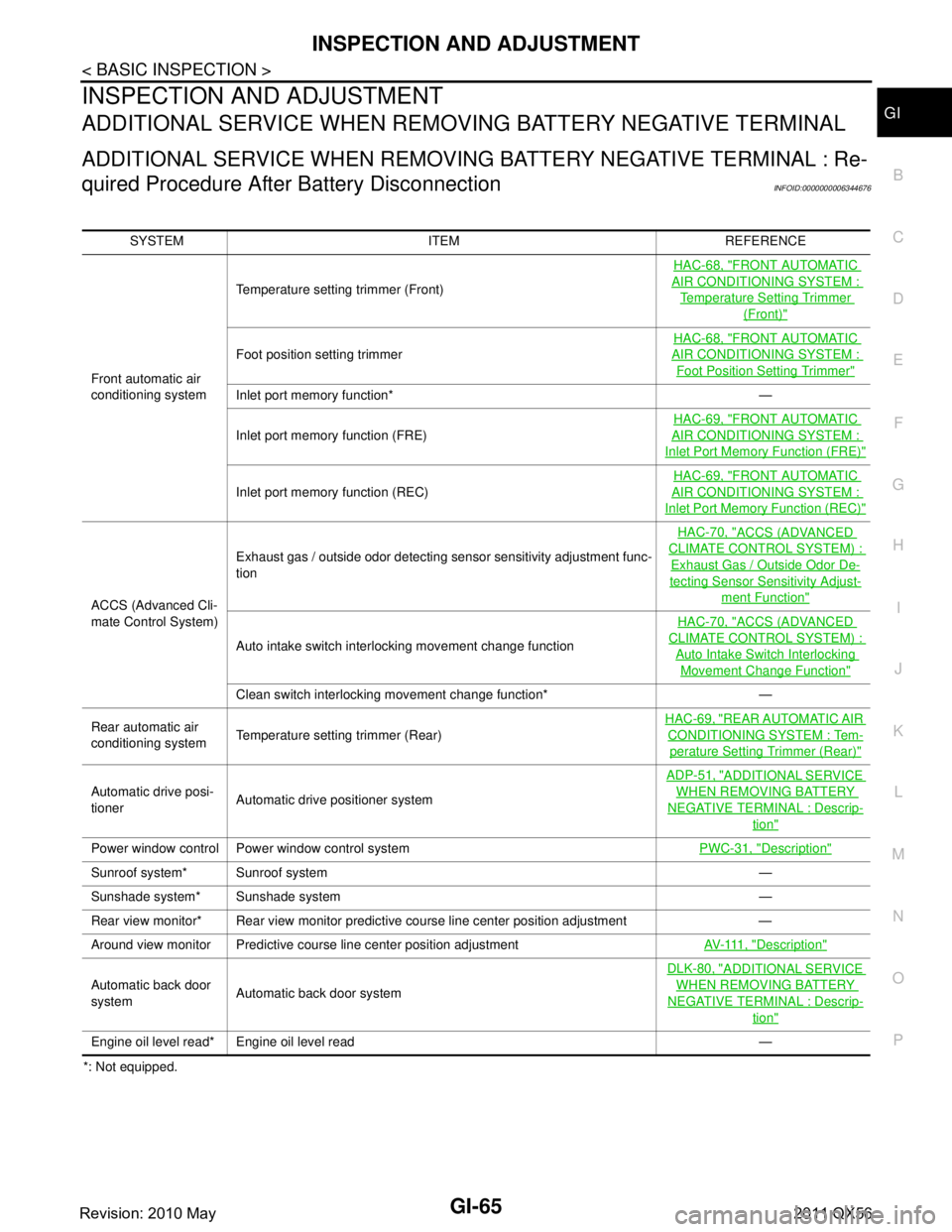
INSPECTION AND ADJUSTMENTGI-65
< BASIC INSPECTION >
C
DE
F
G H
I
J
K L
M B
GI
N
O PINSPECTION AND ADJUSTMENT
ADDITIONAL SERVICE WHEN REMOVING BATTERY NEGATIVE TERMINAL
ADDITIONAL SERVICE WHEN REMOVING BATTERY NEGATIVE TERMINAL : Re-
quired Procedure After Battery Disconnection
INFOID:0000000006344676
*: Not equipped. SYSTEM ITEM REFERENCE
Front automatic air
conditioning system Temperature setting trimmer (Front)
HAC-68, "
FRONT AUTOMATIC
AIR CONDITIONING SYSTEM :
Temperature Setting Trimmer
(Front)"
Foot position setting trimmer
HAC-68, "
FRONT AUTOMATIC
AIR CONDITIONING SYSTEM :
Foot Position Setting Trimmer"
Inlet port memory function* —
Inlet port memory function (FRE)
HAC-69, "
FRONT AUTOMATIC
AIR CONDITIONING SYSTEM :
Inlet Port Memory
Function (FRE)"
Inlet port memory function (REC) HAC-69, "
FRONT AUTOMATIC
AIR CONDITIONING SYSTEM :
Inlet Port Memory Function (REC)"
ACCS (Advanced Cli-
mate Control System)Exhaust gas / outside odor detecting sensor sensitivity adjustment func-
tion
HAC-70, "
ACCS (ADVANCED
CLIMATE CONTROL SYSTEM) :
Exhaust Gas / Outside Odor De-
tecting Sensor Sensitivity Adjust-
ment Function"
Auto intake switch interlocking movement change function
HAC-70, "
ACCS (ADVANCED
CLIMATE CONTROL SYSTEM) :
Auto Intake Switch Interlocking
Movement Change Function"
Clean switch interlocking movement change function* —
Rear automatic air
conditioning system Temperature setting trimmer (Rear) HAC-69, "
REAR AUTOMATIC AIR
CONDITIONING SYSTEM : Tem-
perature Setting
Trimmer (Rear)"
Automatic drive posi-
tioner Automatic drive positioner system ADP-51, "
ADDITIONAL SERVICE
WHEN REMOVING BATTERY
NEGATIVE TERMINAL : Descrip-
tion"
Power window control Power window control system
PWC-31, "Description"
Sunroof system* Sunroof system —
Sunshade system* Sunshade system —
Rear view monitor* Rear view monitor predictive course line center position adjustment —
Around view monitor Predictive course line center position adjustment AV- 111 , "
Description"
Automatic back door
systemAutomatic back door system DLK-80, "
ADDITIONAL SERVICE
WHEN REMOVING BATTERY
NEGATIVE TERMINAL : Descrip-
tion"
Engine oil level read* Engine oil level read —
Revision: 2010 May2011 QX56
Page 3045 of 5598
GW-16
< REMOVAL AND INSTALLATION >
BACK DOOR WINDOW GLASS
BACK DOOR WINDOW GLASS
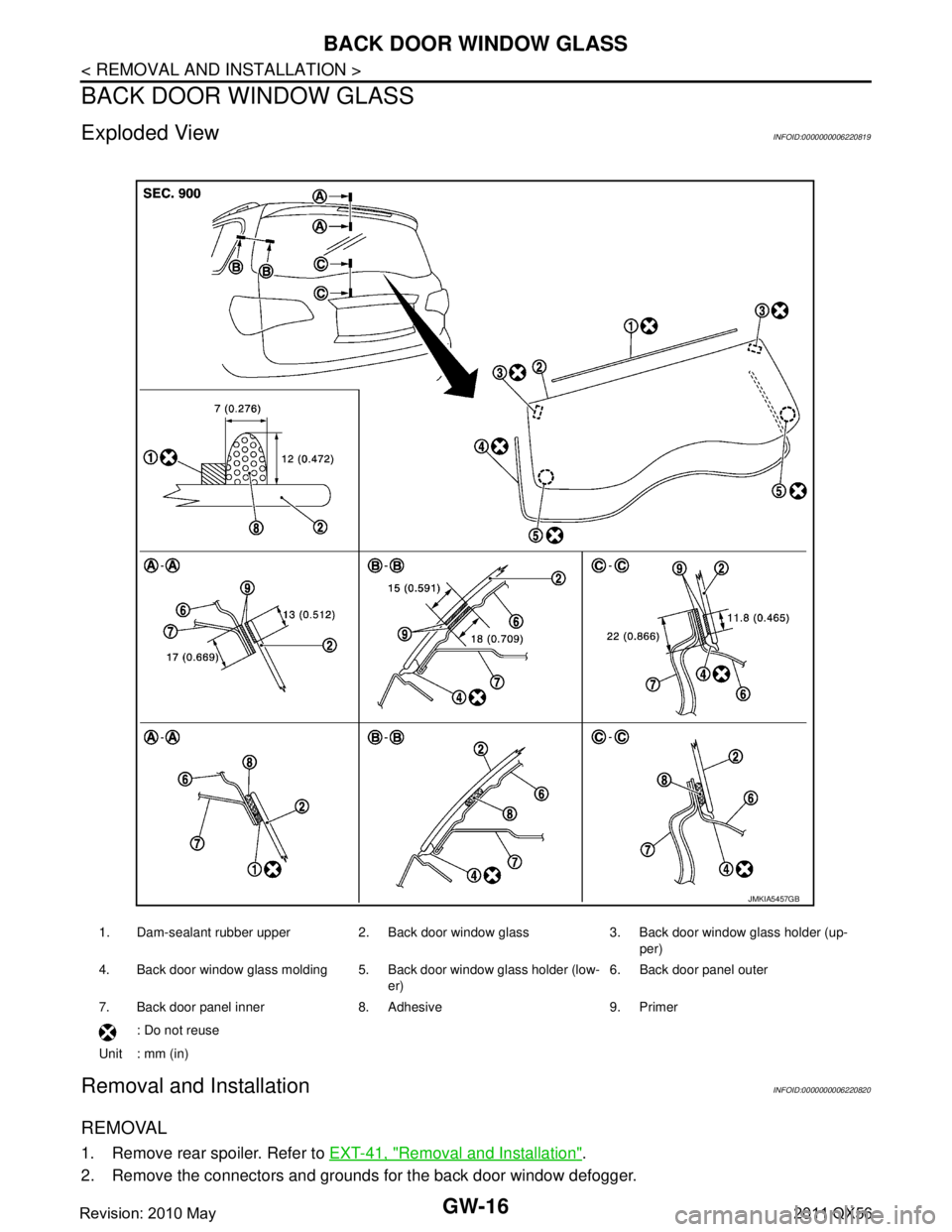
Exploded ViewINFOID:0000000006220819
Removal and InstallationINFOID:0000000006220820
REMOVAL
1. Remove rear spoiler. Refer to EXT-41, "Removal and Installation".
2. Remove the connectors and grounds for the back door window defogger.
1. Dam-sealant rubber upper 2. Back door window glass 3. Back door window glass holder (up- per)
4. Back door window glass molding 5. Back door window glass holder (low- er)6. Back door panel outer
7. Back door panel inner 8. Adhesive 9. Primer : Do not reuse
Unit : mm (in)
JMKIA5457GB
Revision: 2010 May2011 QX56
Page 3061 of 5598
PRECAUTIONSHA-5
< PRECAUTION >
C
DE
F
G H
J
K L
M A
B
HA
N
O P
- Never allow lubricant (A/C System Oil Type R) to come in contact with styrene foam parts. Damage
may result.
REFRIGERANT CONNECTION
A new type refrigerant connection has been introduced to a ll refrigerant lines except the following location.
Expansion valve to evaporator
Refrigerant pressure sensor to liquid tank
WARNING:
Check that all refrigerant is discharged into the recycling equipment and the pressure in the system is
less than atmospheric pressure. Then gradually loo sen the discharge side hose fitting and remove it.
CAUTION:
Observe the following when replacing or cleaning refrigerant cycle components.
Store it in the same way at it is when mounted on the car when the compressor is removed. Failure
to do so will cause lubricant to enter the low-pressure chamber.
Use always a torque wrench and a b ack-up wrench when connecting tubes.
Plug immediately all openings to prevent entry of dust and mois ture after disconnecting tubes.
Connect the pipes at the final stag e of the operation when installing an air conditioner in the vehicle.
Never remove the seal caps of pipes and other compon ents until just before required for connection.
Allow components stored in cool areas to warm to working area temperature before removing seal
caps. This prevents condensation from forming inside A/C components.
Remove thoroughly moisture from the refriger ation system before charging the refrigerant.
Replace always used O-rings.
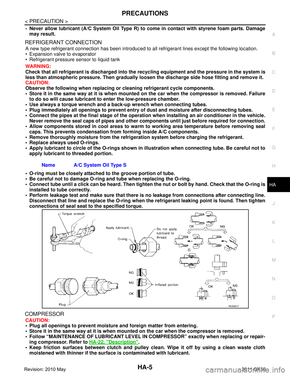
Apply lubricant to circle of th e O-rings shown in illustration when connecting tube. Be careful not to
apply lubricant to threaded portion.
O-ring must be closely attached to the groove portion of tube.
Be careful not to damage O-ring and tube when replacing the O-ring.
Connect tube until a click can be heard. Then tighten the nut or bolt by hand. Check that the O-ring is
installed to tube correctly.
Perform leakage test and make sure that there is no leakage from connections after connecting line.
Disconnect that line and replace the O-ring when the refrigerant leaking point is found. Then tighten
connections of seal seat to the specified torque.
COMPRESSOR
CAUTION:
Plug all openings to prevent moisture and foreign matter from entering.
Store it in the same way at it is when moun ted on the car when the compressor is removed.
Follow “MAINTENANCE OF LUBRICANT LEVEL IN CO MPRESSOR” exactly when replacing or repair-
ing compressor. Refer to HA-22, "
Description".
Keep friction surfaces between clutch and pulley cl ean. Wipe it off by using a clean waste cloth
moistened with thinner if the surface is contaminated with lubricant.
Name A/C System Oil Type S
RHA861F
Revision: 2010 May2011 QX56
Page 3063 of 5598
PRECAUTIONSHA-7
< PRECAUTION >
C
DE
F
G H
J
K L
M A
B
HA
N
O P
The lubricant contained inside the vacuum pump is not compatible
with the specified lubricant for HFC-134a (R-134a) A/C systems.
The vent side of the vacuum pump is exposed to atmospheric pres-
sure. So the vacuum pump lubricant may migrate out of the pump
into the service hose. This is possible when the pump is switched
OFF after evacuation (vacuuming) and hose is connected to it.
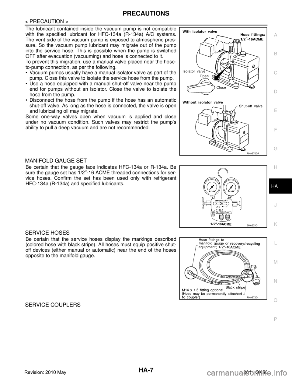
To prevent this migration, use a manual valve placed near the hose-
to-pump connection, as per the following.
Vacuum pumps usually have a manual isolator valve as part of the
pump. Close this valve to isolate the service hose from the pump.
Use a hose equipped with a manual shut-off valve near the pump end for pumps without an isolator. Close the valve to isolate the
hose from the pump.
Disconnect the hose from the pum p if the hose has an automatic
shut-off valve. As long as the hose is connected, the valve is open
and lubricating oil may migrate.
Some one-way valves open when vacuum is applied and close
under no vacuum condition. Such valves may restrict the pump’s
ability to pull a deep vacuum and are not recommended.
MANIFOLD GAUGE SET
Be certain that the gauge face indicates HFC-134a or R-134a. Be
sure the gauge set has 1/2 ″-16 ACME threaded connections for ser-
vice hoses. Confirm the set has been used only with refrigerant
HFC-134a (R-134a) and specified lubricants.
SERVICE HOSES
Be certain that the service hoses display the markings described
(colored hose with black stripe). A ll hoses must equip positive shut-
off devices (either manual or automatic) near the end of the hoses
opposite to the manifold gauge.
SERVICE COUPLERS
RHA270DA
SHA533D
RHA272D
Revision: 2010 May2011 QX56