2011 INFINITI QX56 oil
[x] Cancel search: oilPage 3100 of 5598

HA-44
< REMOVAL AND INSTALLATION >
A/C UNIT ASSEMBLY
INSTALLATION
Note the following items, and install in the reverse order of removal.
CAUTION:
Replace O-rings with new ones. Then apply compressor oil to them when installing.
When install the intake sensor, set the same position before replacement.
Never rotate the bracket insertion part when removing and installing the intake sensor.
Perform lubricant adjusting procedure af ter installing new evaporator. Refer to HA-22, "
Lubricant
Adjusting Procedure for Components Replacement Except Compressor".
HEATER CORE
HEATER CORE : Removal and InstallationINFOID:0000000006276185
REMOVAL
1. Remove heater & cooling unit assembly. Refer to HA-42, "HEATER & COOLING UNIT ASSEMBLY :
Removal and Installation".
2. Remove mounting screws, and then remove heater core pipe cover.
3. Remove mode door motor. Refer to HAC-153, "
MODE DOOR MOTOR : Removal and Installation".
4. Remove main link, foot door link and foot door lever. Refer to HAC-152, "
Exploded View".
5. Remove mounting screws, and then remove foot duct (assist side). Refer to VTL-11, "
FLOOR DUCT 1 :
Removal and Installation".
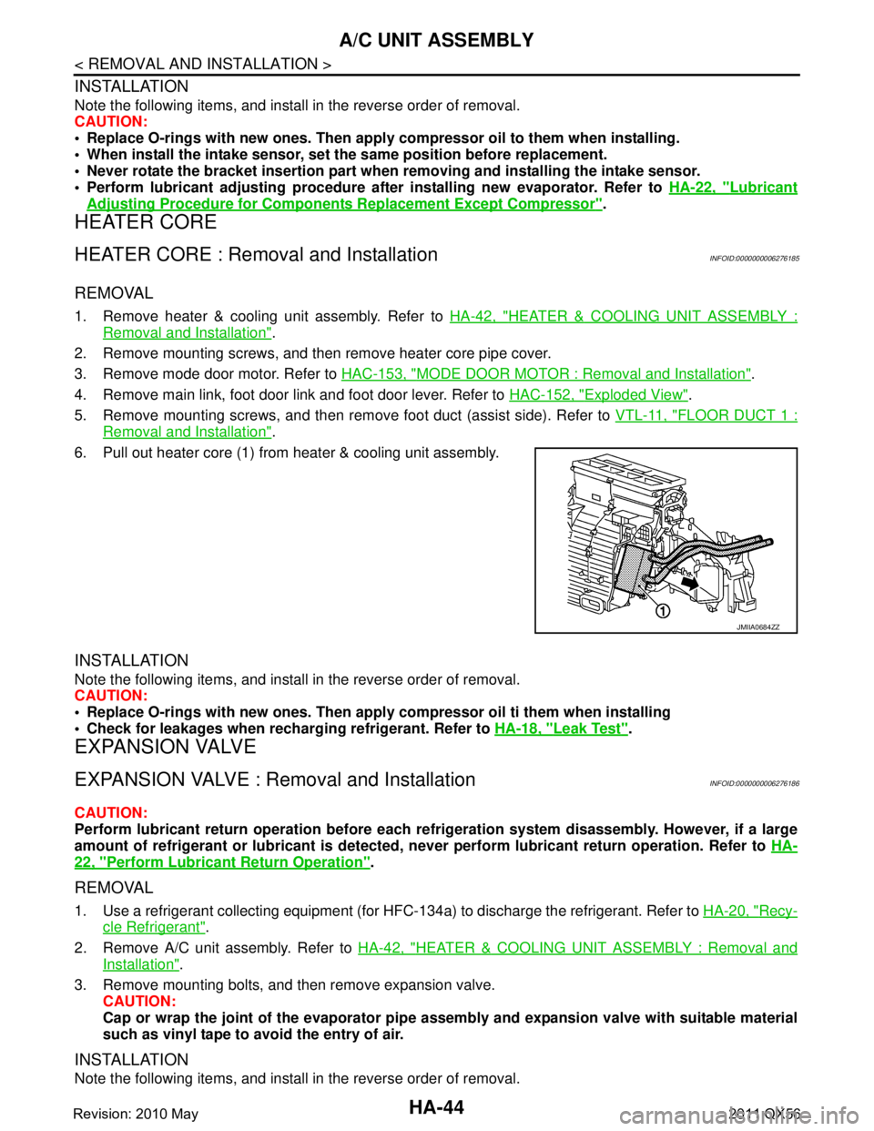
6. Pull out heater core (1) from heater & cooling unit assembly.
INSTALLATION
Note the following items, and install in the reverse order of removal.
CAUTION:
Replace O-rings with new ones. Then apply compressor oil ti them when installing
Check for leakages when recharging refrigerant. Refer to HA-18, "
Leak Test".
EXPANSION VALVE
EXPANSION VALVE : Removal and InstallationINFOID:0000000006276186
CAUTION:
Perform lubricant return operation before each refrigeration system disassembly. However, if a large
amount of refrigerant or lubrican t is detected, never perform lubricant return operation. Refer to HA-
22, "Perform Lubricant Return Operation".
REMOVAL
1. Use a refrigerant collecting equipment (for HF C-134a) to discharge the refrigerant. Refer to HA-20, "Recy-
cle Refrigerant".
2. Remove A/C unit assembly. Refer to HA-42, "
HEATER & COOLING UNIT ASSEMBLY : Removal and
Installation".
3. Remove mounting bolts, and then remove expansion valve. CAUTION:
Cap or wrap the joint of the evaporator pipe assembly and expansion valve with suitable material
such as vinyl tape to avoid the entry of air.
INSTALLATION
Note the following items, and install in the reverse order of removal.
JMIIA0684ZZ
Revision: 2010 May2011 QX56
Page 3101 of 5598

A/C UNIT ASSEMBLYHA-45
< REMOVAL AND INSTALLATION >
C
DE
F
G H
J
K L
M A
B
HA
N
O P
CAUTION:
Replace O-rings with new ones. Then apply compressor oil to them when installing.
Check for leakages when recharging refrigerant. Refer to HA-18, "
Leak Test".
Revision: 2010 May2011 QX56
Page 3104 of 5598

HA-48
< REMOVAL AND INSTALLATION >
REAR A/C UNIT
CAUTION:
Cap or wrap the joint of the A/C piping with suitable material such as vinyl tape to avoid the entry
of air.
6. Remove clamps, and then disconnect rear heater pipe from rear cooler pipe assembly.
7. Remove jack from the vehicle.
8. Remove mounting bolts and nuts, and then remove rear A/C unit assembly.
INSTALLATION
Note the following items, and install in the reverse order of removal.
CAUTION:
Replace O-rings with new ones. Then apply compressor oil to them when installing.
Check for leakages when recharging refrigerant. Refer to HA-18, "
Leak Test".
EVAPORATOR
EVAPORATOR : Removal and InstallationINFOID:0000000006276189
REMOVAL
1. Remove rear A/C unit assembly. Refer to HA-47, "REAR A/C UNIT ASSEMBLY : Removal and Installa-
tion".
2. Disassemble rear A/C unit, and then remove rear evaporator assembly.
3. Remove mounting bolt, and then remove rear evaporator from rear evaporator assembly.
INSTALLATION
Note the following items, and install in the reverse order of removal.
CAUTION:
Replace O-rings with new ones. Then apply compressor oil to them when installing.
Check for leakages when recharging refrigerant. Refer to HA-18, "
Leak Test".
EVAPORATOR PIPE ASSEMBLY
EVAPORATOR PIPE ASSEMBLY : Removal and InstallationINFOID:0000000006276190
REMOVAL
1. Remove rear evaporator assembly. Refer to HA-48, "EVAPORATOR : Removal and Installation".
2. Remove mounting bolts, and then rear expansion valve from rear evaporator assembly. CAUTION:
Cap or wrap the joint of the A/C piping and rear expansion valve with suitable material such as
vinyl tape to avoid the entry of air.
3. Remove mounting bolts, and then remove evaporat or pipe assembly from evaporator assembly.
INSTALLATION
Note the following items, and install in the reverse order of removal.
CAUTION:
Replace O-rings with new ones. Then apply compressor oil to them when installing.
Check for leakages when recharging refrigerant. Refer to HA-18, "
Leak Test".
HEATER CORE
HEATER CORE : Removal and InstallationINFOID:0000000006276191
REMOVAL
1. Remove rear A/C unit assembly. Refer to HA-47, "REAR A/C UNIT ASSEMBLY : Removal and Installa-
tion"
2. Remove grommet from pipe bracket.
3. Remove mounting screws and then remove pipe bracket.
4. Remove mounting screw, and then heater pipe clamp.
Revision: 2010 May2011 QX56
Page 3105 of 5598

REAR A/C UNITHA-49
< REMOVAL AND INSTALLATION >
C
DE
F
G H
J
K L
M A
B
HA
N
O P
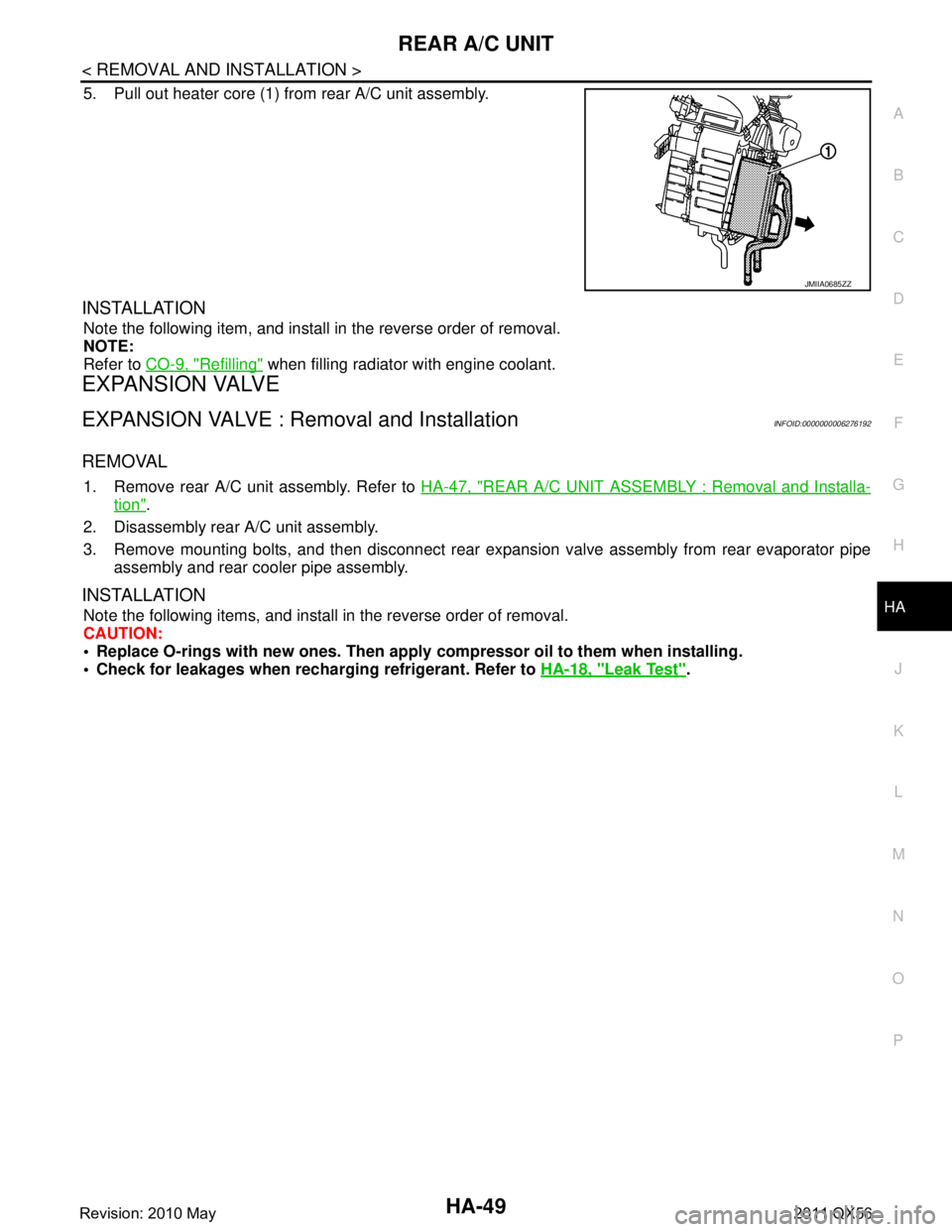
5. Pull out heater core (1) from rear A/C unit assembly.
INSTALLATION
Note the following item, and install in the reverse order of removal.
NOTE:
Refer to CO-9, "
Refilling" when filling radiator with engine coolant.
EXPANSION VALVE
EXPANSION VALVE : Removal and InstallationINFOID:0000000006276192
REMOVAL
1. Remove rear A/C unit assembly. Refer to HA-47, "REAR A/C UNIT ASSEMBLY : Removal and Installa-
tion".
2. Disassembly rear A/C unit assembly.
3. Remove mounting bolts, and then disconnect rear exp ansion valve assembly from rear evaporator pipe
assembly and rear cooler pipe assembly.
INSTALLATION
Note the following items, and install in the reverse order of removal.
CAUTION:
Replace O-rings with new ones. Then apply compressor oil to them when installing.
Check for leakages when recharging refrigerant. Refer to HA-18, "
Leak Test".
JMIIA0685ZZ
Revision: 2010 May2011 QX56
Page 3106 of 5598

HA-50
< SERVICE DATA AND SPECIFICATIONS (SDS)
SERVICE DATA AND SPECIFICATIONS (SDS)
SERVICE DATA AND SPECIFICATIONS (SDS)
SERVICE DATA AND SPECIFICATIONS (SDS)
CompressorINFOID:0000000006276197
LubricantINFOID:0000000006276198
RefrigerantINFOID:0000000006276199
Engine Idling SpeedINFOID:0000000006276200
Refer to EC-538, "Idle Speed".
Belt TensionINFOID:0000000006276201
Refer to EM-20, "TensionAdjustment".
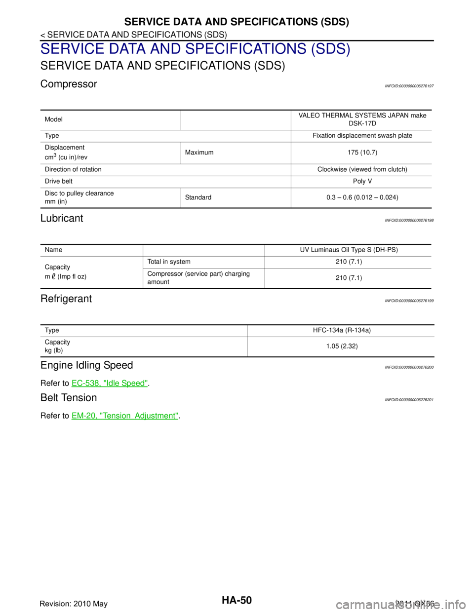
Model VALEO THERMAL SYSTEMS JAPAN make
DSK-17D
Ty p e Fixation displacement swash plate
Displacement
cm
3 (cu in)/rev Maximum 175 (10.7)
Direction of rotation Clockwise (viewed from clutch)
Drive belt Poly V
Disc to pulley clearance
mm (in) Standard 0.3 – 0.6 (0.012 – 0.024)
Name
UV Luminaus Oil Type S (DH-PS)
Capacity
m (Imp fl oz) Total in system 210 (7.1)
Compressor (service part) charging
amount
210 (7.1)
Ty p e
HFC-134a (R-134a)
Capacity
kg (lb) 1.05 (2.32)
Revision: 2010 May2011 QX56
Page 3118 of 5598
![INFINITI QX56 2011 Factory Service Manual
HAC-12
< SYSTEM DESCRIPTION >[AUTOMATIC AIR CONDITIONING]
COMPONENT PARTS
Aspirator
INFOID:0000000006275856
The aspirator generates the vacuum by the air blown from the heater
& cooling unit and draw INFINITI QX56 2011 Factory Service Manual
HAC-12
< SYSTEM DESCRIPTION >[AUTOMATIC AIR CONDITIONING]
COMPONENT PARTS
Aspirator
INFOID:0000000006275856
The aspirator generates the vacuum by the air blown from the heater
& cooling unit and draw](/manual-img/42/57033/w960_57033-3117.png)
HAC-12
< SYSTEM DESCRIPTION >[AUTOMATIC AIR CONDITIONING]
COMPONENT PARTS
Aspirator
INFOID:0000000006275856
The aspirator generates the vacuum by the air blown from the heater
& cooling unit and draws the air of the passenger room to the front
in-vehicle sensor area via the aspirator duct.
Front Blower MotorINFOID:0000000006275857
The front blower motor utilizes a brush-less motor with a rotating
magnet. Quietness is improved comparing to a conventional motor
(brush motor) that rotates coil while brush functions as contact
points.
Front display Front display indicates operation status of ACCS (advanced climate control
system).
Heater & cooling unit as-
sembly Ionizer Ionizer generates an approximately equal proportional amount of positive
and negative ions in the air.
Preset switch Preset switch is integrated with front A/C control and AV operation switch.
Front A/C control operation signal is transmitted from preset switch to AV
control unit via communication line.
Component Description
RJIA1804E
RJIA2467J
ZHA152H
Revision: 2010 May2011 QX56
Page 3119 of 5598
![INFINITI QX56 2011 Factory Service Manual
COMPONENT PARTSHAC-13
< SYSTEM DESCRIPTION > [AUTOMATIC AIR CONDITIONING]
C
D
E
F
G H
J
K L
M A
B
HAC
N
O P
Rear Blower MotorINFOID:0000000006275858
The rear blower motor utilizes a brush-less motor INFINITI QX56 2011 Factory Service Manual
COMPONENT PARTSHAC-13
< SYSTEM DESCRIPTION > [AUTOMATIC AIR CONDITIONING]
C
D
E
F
G H
J
K L
M A
B
HAC
N
O P
Rear Blower MotorINFOID:0000000006275858
The rear blower motor utilizes a brush-less motor](/manual-img/42/57033/w960_57033-3118.png)
COMPONENT PARTSHAC-13
< SYSTEM DESCRIPTION > [AUTOMATIC AIR CONDITIONING]
C
D
E
F
G H
J
K L
M A
B
HAC
N
O P
Rear Blower MotorINFOID:0000000006275858
The rear blower motor utilizes a brush-less motor with a rotating
magnet. Quietness is improved comp aring to a conventional motor
(brush motor) that rotates coil while brush functions as contact
points.
Refrigerant Pressure SensorINFOID:0000000006275859
Description
Refrigerant pressure sensor is installed to upper porti on of liquid tank. The refrigerant pressure sensor con-
verts high-pressure side refrigerant pressure into vo ltage and outputs it to ECM. ECM operates cooling system
protection and idle speed control according to voltage value that is input.
Structure and operation
The refrigerant pressure sensor is a capacitance type sensor. It consists of a pressure detection area and a
signal processing area. The pressure detection area, wh ich is a variable capacity condenser, changes internal
static capacitance according to pressure force. The signal processing area detects the static capacitance of
the pressure detection area, converts the static capacitance into a voltage value, and transmits the voltage
value to ECM.
RJIA2467J
ZHA152H
PBIB2657E
Revision: 2010 May2011 QX56
Page 3123 of 5598
![INFINITI QX56 2011 Factory Service Manual
SYSTEMHAC-17
< SYSTEM DESCRIPTION > [AUTOMATIC AIR CONDITIONING]
C
D
E
F
G H
J
K L
M A
B
HAC
N
O P
FRONT AUTOMATIC AIR CONDITIONIN G SYSTEM : Air Outlet ControlINFOID:0000000006275864
While air out INFINITI QX56 2011 Factory Service Manual
SYSTEMHAC-17
< SYSTEM DESCRIPTION > [AUTOMATIC AIR CONDITIONING]
C
D
E
F
G H
J
K L
M A
B
HAC
N
O P
FRONT AUTOMATIC AIR CONDITIONIN G SYSTEM : Air Outlet ControlINFOID:0000000006275864
While air out](/manual-img/42/57033/w960_57033-3122.png)
SYSTEMHAC-17
< SYSTEM DESCRIPTION > [AUTOMATIC AIR CONDITIONING]
C
D
E
F
G H
J
K L
M A
B
HAC
N
O P
FRONT AUTOMATIC AIR CONDITIONIN G SYSTEM : Air Outlet ControlINFOID:0000000006275864
While air outlet is in automatic control, A/C auto amp. selects the
front mode door position depending on a target front air mix door
angle and outlet air temperature calculated from sunload.
If ambient temperature is excessively low, D/F is selected to pre- vent windshield fogging when air outlet is set to FOOT.
FRONT AUTOMATIC AIR CONDITIONIN G SYSTEM : Compressor Control
INFOID:0000000006275865
DESCRIPTION
When the compressor activation condition is satisfied while blower motor is activated, A/C auto amp. trans-
mits A/C ON signal and blower fan ON signal to ECM via CAN communication.
ECM judges that the compressor can be activated depending on each sensors state (refrigerant pressure sensor signal, and others). And transmits A/C compress or request signal to IPDM E/R via CAN communica-
tion.
IPDM E/R turns A/C relay ON and activates the compressor depending on request from ECM.
COMPRESSOR PROTECTION CONTROL AT PRESSURE MALFUNCTION
When high-pressure side value that is detected by refri gerant pressure sensor is as per the following state,
ECM requests IPDM E/R to turn A/C relay OFF and stops the compressor.
3.12 MPa (31.82 kg/cm
2, 452.4 psi) or more (When the engine speed is less than 1,500 rpm)
2.74 MPa (27.95 kg/cm
2, 397.3 psi) or more (When the engine speed is 1,500 rpm or more)
0.14 MPa (1.43 kg/cm
2, 20.3 psi) or less
COMPRESSOR OIL CIRCULATION CONTROL
When the engine starts while the engine coolant temperature is 56 °C (133 °F) or less, ECM activates the com-
pressor for approximately 6 seconds and circulates the compressor lubricant once.
LOW TEMPERATURE PROTECTION CONTROL
When intake sensor detects that front evaporator fin temperature is
2.5 °C (37 °F) or less, A/C auto amp. requests ECM to turn com-
pressor OFF, and stops the compressor.
When the front evaporator fin temperature returns to 5.0 °C (41 °F)
or more, the compressor is activated.
OPERATING RATE CONTROL
When set temperature is other than fully cold or air out let is “VENT”, “B/L” or “FOOT” A/C auto amp. controls
the compressor activation depending on ambient temperature.
AIR CONDITIONING CUT CONTROL
When set engine is running is excessively high load conditi on, ECM requests IPDM E/R to turn A/C relay OFF,
and stops the compressor. Refer to EC-47, "
AIR CONDITIONING CUT CONTRO L : System Description" for
details.
JMIIA0730GB
JMIIA0742GB
Revision: 2010 May2011 QX56