2011 INFINITI QX56 oil
[x] Cancel search: oilPage 2951 of 5598
FRONT COIL SPRING AND SHOCK ABSORBERFSU-9
< REMOVAL AND INSTALLATION >
C
DF
G H
I
J
K L
M A
B
FSU
N
O P
REMOVAL AND INSTALLATION
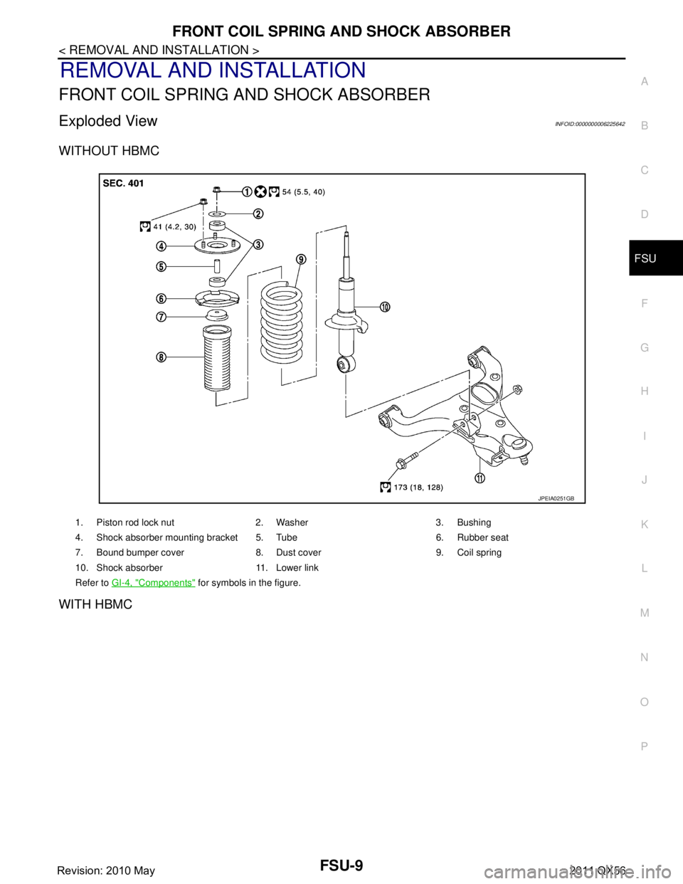
FRONT COIL SPRING AND SHOCK ABSORBER
Exploded ViewINFOID:0000000006225642
WITHOUT HBMC
WITH HBMC
1. Piston rod lock nut 2. Washer 3. Bushing
4. Shock absorber mounting bracket 5. Tube 6. Rubber seat
7. Bound bumper cover 8. Dust cover 9. Coil spring
10. Shock absorber 11. Lower link
Refer to GI-4, "
Components" for symbols in the figure.
JPEIA0251GB
Revision: 2010 May2011 QX56
Page 2952 of 5598
FSU-10
< REMOVAL AND INSTALLATION >
FRONT COIL SPRING AND SHOCK ABSORBER
CAUTION:
The shock absorber assembly cannot be disassembled.
Removal and InstallationINFOID:0000000006225643
REMOVAL
1. Reduce system pressure. (With HBMC) Refer to SCS-18, "Work Procedure".
CAUTION:
Inadvertent piping removal causes fluid to splatter.
2. Remove tires with power tool. Refer to WT-64, "
Removal and Installation".
3. Remove brake hose bracket from steering knuckle. Refer to BR-23, "
FRONT : Removal and Installation".
4. Remove caliper assembly mounting bolts. Hang caliper assembly in a place where it will not interfere with work. Refer to BR-37, "
BRAKE CALIPER ASSEMBLY : Removal and Installation".
CAUTION:
Never depress brake pedal while brake caliper is removed.
5. Remove disc rotor. Refer to FA X - 8 , "
Removal and Installation" (2WD), FAX-18, "Removal and Installation"
(4WD).
6. Remove wheel sensor and harness connector. Refer to BRC-134, "
FRONT WHEEL SENSOR : Removal
and Installation".
CAUTION:
Never pull on wheel sensor harness.
7. Remove steering outer socket fr om steering knuckle. Refer to ST-42, "
Removal and Installation".
8. Remove height sensor from upper link (right side). Refer to EXL-136, "
Removal and Installation".
9. Set suitable jack under lower link.
10. Remove stabilizer connecting rod from lower link. (Without HBMC) Refer to FSU-20, "
Removal and Instal-
lation".
11. Separate upper link from steering knuckle. Refer to FSU-17, "
Removal and Installation".
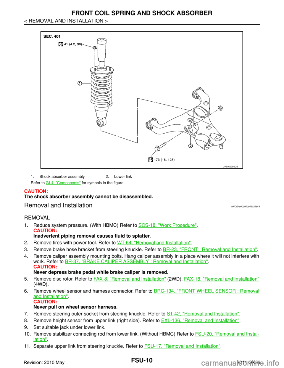
1. Shock absorber assembly 2. Lower link
Refer to GI-4, "
Components" for symbols in the figure.
JPEIA0256GB
Revision: 2010 May2011 QX56
Page 2953 of 5598
FRONT COIL SPRING AND SHOCK ABSORBERFSU-11
< REMOVAL AND INSTALLATION >
C
DF
G H
I
J
K L
M A
B
FSU
N
O P
12. Separate drive shaft from steering knuckle. (4WD) Refer to FAX-22, "Removal and Installation".
13. Remove front tube assembly A and front tube asse mbly B from shock absorber. (With HBMC) Refer to
SCS-32, "
FRONT TUBE ASSEMBLY : Removal and Installation".
14. Remove shock absorber.
15. Perform inspection after removal. (With HBMC) Refer to FSU-12, "
Inspection and Adjustment".
INSTALLATION
Note the following, and install in the reverse order of removal.
Never tap on the ball joint cap of the stabilizer connecting rod with a hammer or a similar item when inserting
the stabilizer connecting rod into the lower link. (Without HBMC)
Perform final tightening of bolts and nuts at the shock absorber lower side (rubber bushing), under unladen
conditions with tires on level ground.
Perform inspection after installation. Refer to FSU-12, "
Inspection and Adjustment".
Perform adjustment after installation. (With HBMC) Refer to FSU-12, "
Inspection and Adjustment".
After replacing the shock absorber, always follow the disposal procedure to discard the shock absorber.
Refer to FSU-13, "
Disposal".
Disassembly and AssemblyINFOID:0000000006273960
CAUTION:
The shock absorber assembly can not be disassembled. (With HBMC)
DISASSEMBLY (WITHOUT HBMC)
CAUTION:
Never damage shock absorber piston rod wh en removing components from shock absorber.
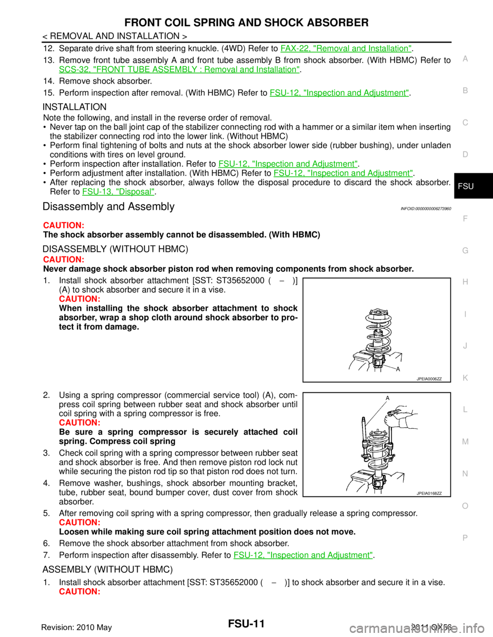
1. Install shock absorber attachment [SST: ST35652000 ( −)]
(A) to shock absorber and secure it in a vise.
CAUTION:
When installing the shock ab sorber attachment to shock
absorber, wrap a shop cloth around shock absorber to pro-
tect it from damage.
2. Using a spring compressor (commercial service tool) (A), com- press coil spring between rubber seat and shock absorber until
coil spring with a spring compressor is free.
CAUTION:
Be sure a spring compresso r is securely attached coil
spring. Compress coil spring
3. Check coil spring with a spring compressor between rubber seat and shock absorber is free. And then remove piston rod lock nut
while securing the piston rod tip so that piston rod does not turn.
4. Remove washer, bushings, shock absorber mounting bracket, tube, rubber seat, bound bumper cover, dust cover from shock
absorber.
5. After removing coil spring with a spring compressor, then gradually release a spring compressor. CAUTION:
Loosen while making sure coil spri ng attachment position does not move.
6. Remove the shock absorber at tachment from shock absorber.
7. Perform inspection after disassembly. Refer to FSU-12, "
Inspection and Adjustment".
ASSEMBLY (WITHOUT HBMC)
1. Install shock absorber attachment [SST: ST35652000 ( −)] to shock absorber and secure it in a vise.
CAUTION:
JPEIA0006ZZ
JPEIA0168ZZ
Revision: 2010 May2011 QX56
Page 2954 of 5598
FSU-12
< REMOVAL AND INSTALLATION >
FRONT COIL SPRING AND SHOCK ABSORBER
When installing the shock absorber attachment to shock absorber, wrap a shop cloth around
shock absorber to protect it from damage.
2. Compress coil spring using a spring compressor (commercial service tool), and install it onto shock absorber.
CAUTION:
Be sure a spring compressor is securely attach ed to coil spring. Compress coil spring.
Set coil spring so that its paint marks face downward.
3. Apply soapy water to dust cover. CAUTION:
Never use machine oil.
4. Install dust cover, bound bumper cover, rubber seat , bushings, tube, shock absorber mounting bracket,
and washer to shock absorber.
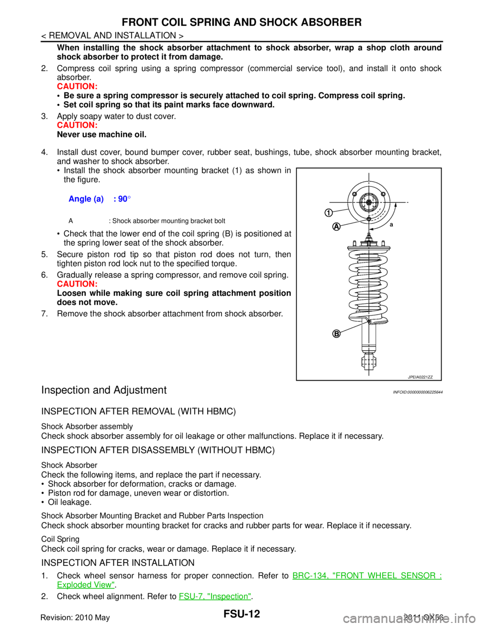
Install the shock absorber mounting bracket (1) as shown in the figure.
Check that the lower end of the coil spring (B) is positioned at the spring lower seat of the shock absorber.
5. Secure piston rod tip so that piston rod does not turn, then tighten piston rod lock nut to the specified torque.
6. Gradually release a spring compressor, and remove coil spring. CAUTION:
Loosen while making sure co il spring attachment position
does not move.
7. Remove the shock absorber attachment from shock absorber.
Inspection and AdjustmentINFOID:0000000006225644
INSPECTION AFTER REMOVAL (WITH HBMC)
Shock Absorber assembly
Check shock absorber assembly for oil leakage or other malfunctions. Replace it if necessary.
INSPECTION AFTER DISASSEMBLY (WITHOUT HBMC)
Shock Absorber
Check the following items, and replace the part if necessary.
Shock absorber for deformation, cracks or damage.
Piston rod for damage, uneven wear or distortion.
Oil leakage.
Shock Absorber Mounting Bracket and Rubber Parts Inspection
Check shock absorber mounting bracket for cracks and rubber parts for wear. Replace it if necessary.
Coil Spring
Check coil spring for cracks, wear or damage. Replace it if necessary.
INSPECTION AFTER INSTALLATION
1. Check wheel sensor harness for proper connection. Refer to BRC-134, "FRONT WHEEL SENSOR :
Exploded View".
2. Check wheel alignment. Refer to FSU-7, "
Inspection".
Angle (a) : 90
°
A : Shock absorber mounting bracket bolt
JPEIA0221ZZ
Revision: 2010 May2011 QX56
Page 2955 of 5598
FRONT COIL SPRING AND SHOCK ABSORBERFSU-13
< REMOVAL AND INSTALLATION >
C
DF
G H
I
J
K L
M A
B
FSU
N
O P
3. Adjust neutral position of steering angle sensor. Refer to BRC-64, "Work Procedure".
4. Adjust levelizer adjustment of height sensor. Refer to EXL-61, "
LEVELIZER ADJUSTMENT : Special
Repair Requirement".
ADJUSTMENT AFTER INSTALLATION (WITH HBMC)
Bleed air from the HBMC. Refer to SCS-18, "Work Procedure".
DisposalINFOID:0000000006225645
WITHOUT HBMC
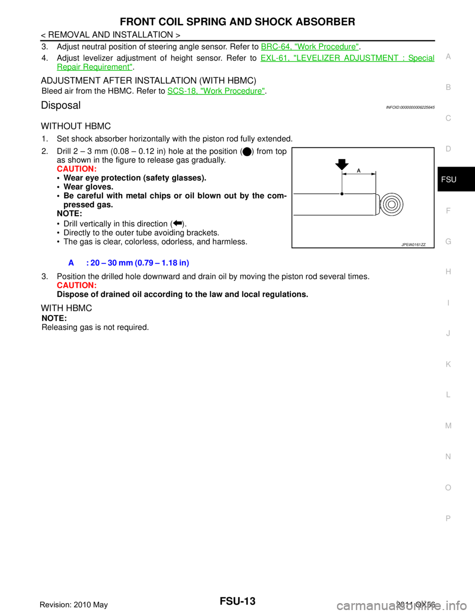
1. Set shock absorber horizontally with the piston rod fully extended.
2. Drill 2 – 3 mm (0.08 – 0.12 in) hole at the position ( ) from top
as shown in the figure to release gas gradually.
CAUTION:
Wear eye protection (safety glasses).
Wear gloves.
Be careful with metal chips or oil blown out by the com-
pressed gas.
NOTE:
Drill vertically in this direction ( ).
Directly to the outer tube avoiding brackets.
The gas is clear, colorless, odorless, and harmless.
3. Position the drilled hole downward and drain oil by moving the piston rod several times. CAUTION:
Dispose of drained oil according to the law and local regulations.
WITH HBMC
NOTE:
Releasing gas is not required.A : 20 – 30 mm (0.79 – 1.18 in)
JPEIA0161ZZ
Revision: 2010 May2011 QX56
Page 2965 of 5598

GI-1
GENERAL INFORMATION
C
DE
F
G H
I
J
K L
M B
GI
SECTION GI
N
O P
CONTENTS
GENERAL INFORMATION
HOW TO USE THIS MANU AL ......................3
HOW TO USE THIS MANUAL ....................... .....3
Description .......................................................... ......3
Terms ........................................................................3
Units ..........................................................................3
Contents ....................................................................3
Relation between Illustrations and Descriptions .......4
Components ..............................................................4
HOW TO FOLLOW TROUBLE DIAGNOSES .....6
Description ................................................................6
How to Follow Test Groups in Trouble Diagnosis ......6
Key to Symbols Signifying Measurements or Pro-
cedures ............................................................... ......
7
HOW TO READ WIRING DIAGRAMS ................9
Connector Symbols ............................................. ......9
Sample/Wiring Diagram -Example- .........................10
Connector Information .............................................12
ABBREVIATIONS .......................................... ....14
Abbreviation List .................................................. ....14
TIGHTENING TORQUE OF STANDARD
BOLTS ................................................................
19
Description .......................................................... ....19
Tightening Torque Table (New Standard Includ-
ed) ...........................................................................
19
RECOMMENDED CHEMICAL PRODUCTS
AND SEALANTS ................................................
22
Recommended Chemical Products and Sealants ....22
VEHICLE INFORMATION ............................23
IDENTIFICATION INFORMATION ................. ....23
Model Variation ................................................... ....23
Information About Identification or Model Code ......23
Dimensions .............................................................25
Wheels & Tires ........................................................25
PRECAUTION ..............................................26
PRECAUTIONS .................................................26
Description ........................................................... ....26
Precaution for Supplemental Restraint System
(SRS) "AIR BAG" and "SEAT BELT PRE-TEN-
SIONER" .................................................................
26
Precautions For Xenon Headlamp Service .............26
Precaution Necessary for Steering Wheel Rota-
tion after Battery Disconnect ...................................
27
Precaution for Procedure without Cowl Top Cover ....27
General Precautions ................................................27
Three Way Catalyst .................................................29
Multiport Fuel Injection System or Engine Control
System .....................................................................
29
Hoses ......................................................................29
Engine Oils ..............................................................30
Air Conditioning .......................................................31
Fuel ..........................................................................31
LIFTING POINT .................................................32
Pantograph Jack ......................................................32
Garage Jack and Safety Stand ................................32
2-Pole Lift ................................................................33
TOW TRUCK TOWING .....................................34
Tow Truck Towing ...................................................34
Vehicle Recovery (Freeing a Stuck Vehicle) ...........34
BASIC INSPECTION ...................................36
SERVICE INFORMATION FOR ELECTRICAL
INCIDENT ..........................................................
36
Work Flow ............................................................ ....36
Control Units and Electrical Parts ............................36
How to Check Terminal ...........................................37
Intermittent Incident .................................................40
Circuit Inspection .....................................................43
CONSULT-III/GST CHECKING SYSTEM .........48
Description ...............................................................48
CONSULT-III Function and System Application*1 ....48
Revision: 2010 May2011 QX56
Page 2979 of 5598

ABBREVIATIONSGI-15
< HOW TO USE THIS MANUAL >
C
DE
F
G H
I
J
K L
M B
GI
N
O P
E
F
G
H
ABBREVIATION DESCRIPTION E/T Exhaust temperature
EBD Electric brake force distribution EC Engine control
ECL Engine coolant level
ECM Engine control module ECT Engine coolant temperature
ECV Electrical control valve
EEPROM Electrically erasable programmable read only memory EFT Engine fuel temperature
EGR Exhaust gas recirculation
EGRT Exhaust gas recirculation temperature EGT Exhaust gas temperature
EOP Engine oil pressure EP Exhaust pressure
EPR Exhaust pressure regulator EPS Electronically controlled power steering
ESP Electronic stability program system
EVAP canister Evaporative emission canister EXC Exhaust control
ABBREVIATION DESCRIPTION FC Fan control
FCW Forward collision warning FIC Fuel injector controlFP Fuel pump
FR Front
FRP Fuel rail pressure FRT Fuel rail temperature
FTP Fuel tank pressure FTT Fuel tank temperature
ABBREVIATION DESCRIPTION GND GroundGPS Global positioning systemGST Generic scan tool
ABBREVIATION DESCRIPTION HBMC Hydraulic body-motion control systemHDD Hard disk drive
HO2S Heated oxygen sensor HOC Heated oxidation catalyst
Revision: 2010 May2011 QX56
Page 2990 of 5598
GI-26
< PRECAUTION >
PRECAUTIONS
PRECAUTION
PRECAUTIONS
DescriptionINFOID:0000000006280865
Observe the following precautions to ensure safe and proper servicing. These precautions are not
described in each individual section.
Precaution for Supplemental Restraint S ystem (SRS) "AIR BAG" and "SEAT BELT
PRE-TENSIONER"
INFOID:0000000006280866
The Supplemental Restraint System such as “A IR BAG” and “SEAT BELT PRE-TENSIONER”, used along
with a front seat belt, helps to reduce the risk or severi ty of injury to the driver and front passenger for certain
types of collision. This system includes seat belt switch inputs and dual stage front air bag modules. The SRS
system uses the seat belt switches to determine the front air bag deployment, and may only deploy one front
air bag, depending on the severity of a collision and w hether the front occupants are belted or unbelted.
Information necessary to service the system safely is included in the “SRS AIR BAG” and “SEAT BELT” of this
Service Manual.
WARNING:
To avoid rendering the SRS inopera tive, which could increase the risk of personal injury or death in
the event of a collision that would result in air bag inflation, all maintenance must be performed by
an authorized NISS AN/INFINITI dealer.
Improper maintenance, including in correct removal and installation of the SRS, can lead to personal
injury caused by unintent ional activation of the system. For re moval of Spiral Cable and Air Bag
Module, see the “SRS AIR BAG”.
Do not use electrical test equipmen t on any circuit related to the SRS unless instructed to in this
Service Manual. SRS wiring harnesses can be identi fied by yellow and/or orange harnesses or har-
ness connectors.
PRECAUTIONS WHEN USING POWER TOOLS (AIR OR ELECTRIC) AND HAMMERS
WARNING:
When working near the Air Bag Diagnosis Sensor Unit or other Air Bag System sensors with the
ignition ON or engine running, DO NOT use air or electric power tools or strike near the sensor(s)
with a hammer. Heavy vibration could activate the sensor(s) and deploy the air bag(s), possibly
causing serious injury.
When using air or electric power tools or hammers , always switch the ignition OFF, disconnect the
battery, and wait at least 3 minu tes before performing any service.
Precautions For Xenon Headlamp ServiceINFOID:0000000006280867
WARNING:
Comply with the following warnings to prevent any serious accident.
Disconnect the battery cable (negative terminal) or the power supply fuse before installing, remov-
ing, or touching the xenon headlamp (bulb included). The xenon headlamp contains high-voltage
generated parts.
Never work with wet hands.
Check the xenon headlamp ON-OFF status after assembling it to the vehicle. Never turn the xenon
headlamp ON in other conditions. Connect th e power supply to the vehicle-side connector.
(Turning it ON outside the lamp case m ay cause fire or visual impairments.)
Never touch the bulb glass immediately after turning it OFF. It is extremely hot.
CAUTION:
Comply with the following cautions to prevent any error and malfunction.
Install the xenon bulb securely. (Ins ufficient bulb socket installation may melt the bulb, the connec-
tor, the housing, etc. by high-v oltage leakage or corona discharge.)
Never perform HID circuit in spection with a tester.
Never touch the xenon bulb glass with ha nds. Never put oil and grease on it.
Dispose of the used xenon bulb after packing it in thick vinyl without breaking it.
Never wipe out dirt and cont amination with organic solven t (thinner, gasoline, etc.).
Revision: 2010 May2011 QX56