2011 INFINITI QX56 oil
[x] Cancel search: oilPage 2872 of 5598
REAR BUMPEREXT-17
< REMOVAL AND INSTALLATION >
C
DE
F
G H
I
J
L
M A
B
EXT
N
O P
Removal and InstallationINFOID:0000000006367600
REMOVAL
CAUTION:
Bumper fascia is made of resin. Never apply strong force to it, and be careful to prevent contact with
oil.
1. Fully open back door assembly.
2. Remove rear combination lamp (LH and RH). Refer to EXL-138, "
Removal and Installation".
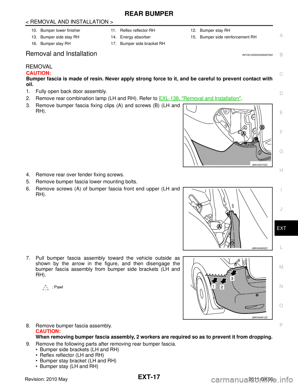
3. Remove bumper fascia fixing clips (A) and screws (B) (LH and RH).
4. Remove rear over fender fixing screws.
5. Remove bumper fascia lower mounting bolts.
6. Remove screws (A) of bumper fascia front end upper (LH and RH).
7. Pull bumper fascia assembly toward the vehicle outside as shown by the arrow in the figure, and then disengage the
bumper fascia assembly from bumper side brackets (LH and
RH).
8. Remove bumper fascia assembly. CAUTION:
When removing bumper fascia assembly, 2 workers ar e required so as to prevent it from dropping.
9. Remove the following parts after removing rear bumper fascia. Bumper side brackets (LH and RH)
Reflex reflector (LH and RH)
Bumper stay bracket (LH and RH)
Bumper stay (LH and RH)
10. Bumper lower finisher 11. Reflex reflector RH 12. Bumper stay RH
13. Bumper side stay RH 14. Energy absorber 15. Bumper side reinforcement RH
16. Bumper stay RH 17. Bumper side bracket RH
JMKIA5370ZZ
JMKIA5460ZZ
: Pawl
JMKIA5461ZZ
Revision: 2010 May2011 QX56
Page 2896 of 5598
REAR SPOILEREXT-41
< REMOVAL AND INSTALLATION >
C
DE
F
G H
I
J
L
M A
B
EXT
N
O P
REAR SPOILER
Exploded ViewINFOID:0000000006367627
Removal and InstallationINFOID:0000000006367628
REMOVAL
1. Remove back door trim. Refer to INT-39, "Removal and Installation".
2. Remove rear spoiler mounting nuts.
3. Cut rear spoiler fixing double-sided tape with cutter knife.
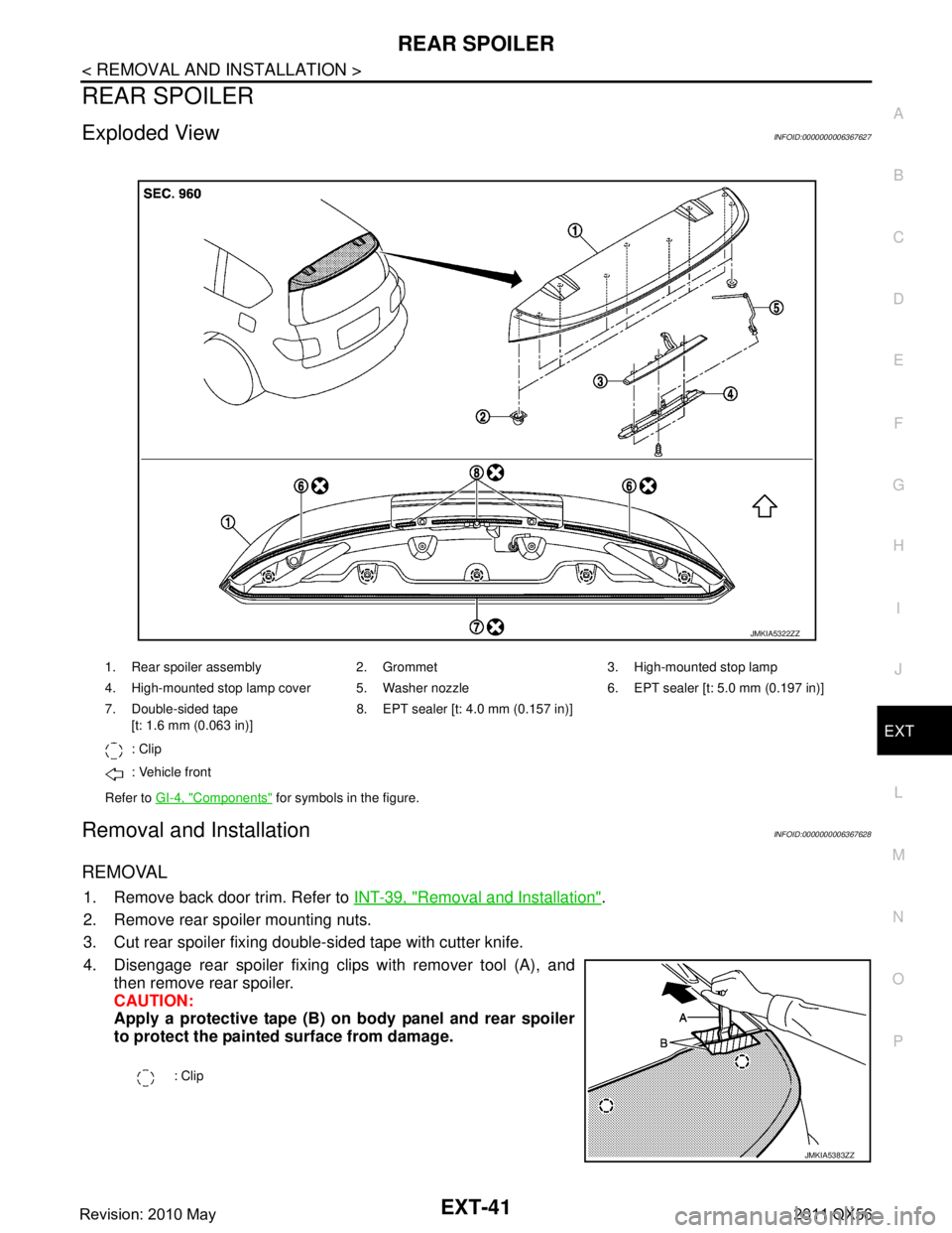
4. Disengage rear spoiler fixing clips with remover tool (A), and then remove rear spoiler.
CAUTION:
Apply a protective tape (B) on body panel and rear spoiler
to protect the painted surface from damage.
1. Rear spoiler assembly 2. Grommet 3. High-mounted stop lamp
4. High-mounted stop lamp cover 5. Washer nozzle 6. EPT sealer [t: 5.0 mm (0.197 in)]
7. Double-sided tape
[t: 1.6 mm (0.063 in)] 8. EPT sealer [t: 4.0 mm (0.157 in)]
: Clip
: Vehicle front
Refer to GI-4, "
Components" for symbols in the figure.
JMKIA5322ZZ
: Clip
JMKIA5383ZZ
Revision: 2010 May2011 QX56
Page 2897 of 5598
EXT-42
< REMOVAL AND INSTALLATION >
REAR SPOILER
5. Remove following parts after removing rear spoiler. High-mounted stop lamp
Grommets
Washer nozzle
INSTALLATION
Note the following items, and then install in the reverse order of removal.
CAUTION:
Be careful no to damage the back door.
Always replace double-sided tape with a new one, if rear spoiler is reused.
Remove double-sided tape remain ing on back door panel and back of rear spoiler with a double-
sided tape remover, after removing rear spoiler.
When installing, visually check the rear spoiler and the clips, then replace them with new parts if
they are damaged.
When installing rear spoiler, check that clips an d bolts are securely fitted in back door panel holes,
and then press them in.
Never wash the vehicle within 24 hours af ter installing so as to keep adhesive.
Revision: 2010 May2011 QX56
Page 2923 of 5598
![INFINITI QX56 2011 Factory Service Manual
FRONT DRIVE SHAFTFAX-23
< REMOVAL AND INSTALLATION > [4WD]
C
EF
G H
I
J
K L
M A
B
FA X
N
O P
Never damage ball joint boot.
11. Remove cotter pin, and then loosen wheel hub lock nut.
12. Patch wheel INFINITI QX56 2011 Factory Service Manual
FRONT DRIVE SHAFTFAX-23
< REMOVAL AND INSTALLATION > [4WD]
C
EF
G H
I
J
K L
M A
B
FA X
N
O P
Never damage ball joint boot.
11. Remove cotter pin, and then loosen wheel hub lock nut.
12. Patch wheel](/manual-img/42/57033/w960_57033-2922.png)
FRONT DRIVE SHAFTFAX-23
< REMOVAL AND INSTALLATION > [4WD]
C
EF
G H
I
J
K L
M A
B
FA X
N
O P
Never damage ball joint boot.
11. Remove cotter pin, and then loosen wheel hub lock nut.
12. Patch wheel hub lock nut with a piece of wood. Hammer the wood to disengage wheel hub and bearing assembly from drive shaft.
CAUTION:
Never place drive shaft joint at an extreme angle. Also be careful not to overextend slide joint.
Never allow drive shaft to hang down without support for or joint sub-assembly, shaft and the
other parts.
NOTE:
Use suitable puller, if wheel hub and bearing assembly and drive shaft cannot be separated even after
performing the above procedure.
13. Remove wheel hub lock nut.
14. Remove fender protector. Refer to EXT-23, "
FENDER PROTECTOR : Removal and Installation".
15. Remove drive shaft from front final drive using the drive shaft attachment [SST: KV40107500 ( −)] (A) and a sliding ham-
mer (commercial service tool) (B) while inserting tip of the drive
shaft attachment between housing and front final drive.
CAUTION:
Never place drive shaft joint at an extreme angle when
removing drive shaft. Also be careful not to overextend
slide joint.
Confirm that the circular clip is attached to the drive shaft.
16. Perform inspection after removal. Refer to FAX-28, "
Inspection".
INSTALLATION
Note the following, and install in the reverse order of removal.
CAUTION:
Always replace final drive side oil seal with new one when installing drive shaft. Refer to DLN-160,
"Removal and Installation"
Place the protector [SST: KV38106300 (−)] (A) onto final drive
to prevent damage to the oil seal while inserting drive shaft. Slide
drive shaft sliding joint and tap with a hammer to install securely.
CAUTION:
Check that circular clip is completely engaged.
Use the following torque range for tightening the wheel hub lock nut.
CAUTION:
Since the drive shaft is assembled by press-fitting, use the tightening torque range for the wheel hub lock nut.
Be sure to use torque wrench to tighten th e wheel hub lock nut. Never use a power tool.
Perform the final tightening of each of parts under unladen conditions, which were removed when removing
wheel hub and bearing assembly and steering knuckle.
Never reuse cotter pin.
Perform inspection after installation. Refer to FAX-28, "
Inspection".
WHEEL SIDE
WHEEL SIDE : Disassembly and AssemblyINFOID:0000000006225404
DISASSEMBLY
1. Fix shaft with a vise.
CAUTION:
Protect shaft when fixing with a vi se using aluminum or copper plates.
2. Remove dust shield from joint sub-assembly.
3. Remove boot bands and then remove boot from joint sub-assembly.
JPDIF0004ZZ
: 118 – 123 N·m (12.1 – 12.5 kg-m, 87 – 90 ft-lb)
JPDIF0023ZZ
Revision: 2010 May2011 QX56
Page 2943 of 5598
FSU-1
SUSPENSION
C
DF
G H
I
J
K L
M
SECTION FSU
A
B
FSU
N
O PCONTENTS
FRONT SUSPENSION
PRECAUTION ................ ...............................2
PRECAUTIONS .............................................. .....2
Precaution for Supplemental Restraint System
(SRS) "AIR BAG" and "SEAT BELT PRE-TEN-
SIONER" ............................................................. ......
2
Precaution Necessary for Steering Wheel Rota-
tion after Battery Disconnect .....................................
2
Precaution for Procedure without Cowl Top Cover ......3
Precautions for Suspension ......................................3
PREPARATION ............................................4
PREPARATION .............................................. .....4
Special Service Tools .......................................... ......4
Commercial Service Tools ........................................4
SYMPTOM DIAGNOSIS ...............................5
NOISE, VIBRATION AND HARSHNESS
(NVH) TROUBLESHOOTING ........................ .....
5
NVH Troubleshooting Chart ................................ ......5
PERIODIC MAINTENANCE ..........................6
FRONT SUSPENSION ASSEMBLY .............. .....6
Inspection ............................................................ ......6
WHEEL ALIGNMENT ..........................................7
Inspection ............................................................ ......7
Adjustment ................................................................7
REMOVAL AND INSTALLATION ................9
FRONT COIL SPRING AND SHOCK AB-
SORBER ............................................................
9
Exploded View ..................................................... .....9
Removal and Installation .........................................10
Disassembly and Assembly .....................................11
Inspection and Adjustment ......................................12
Disposal ...................................................................13
LOWER LINK ....................................................14
Exploded View .........................................................14
Removal and Installation .........................................14
Inspection ................................................................15
UPPER LINK ......................... ............................17
Exploded View ..................................................... ....17
Removal and Installation .........................................17
Inspection ................................................................18
FRONT STABILIZER ........................................20
Exploded View .........................................................20
Removal and Installation .........................................20
Inspection ................................................................20
SERVICE DATA AND SPECIFICATIONS
(SDS) ............... .............................................
21
SERVICE DATA AND SPECIFICATIONS
(SDS) .................................................................
21
Wheel Alignment ................................................. ....21
Ball Joint ..................................................................21
Wheel Height ...........................................................21
Revision: 2010 May2011 QX56
Page 2945 of 5598
PRECAUTIONSFSU-3
< PRECAUTION >
C
DF
G H
I
J
K L
M A
B
FSU
N
O P
5. When the repair work is completed, re-connect both battery cables. With the brake pedal released, turn
the push-button ignition switch from ACC position to ON position, then to LOCK position. (The steering
wheel will lock when the push-button ignition switch is turned to LOCK position.)
6. Perform self-diagnosis check of a ll control units using CONSULT-III.
Precaution for Procedure without Cowl Top CoverINFOID:0000000006271994
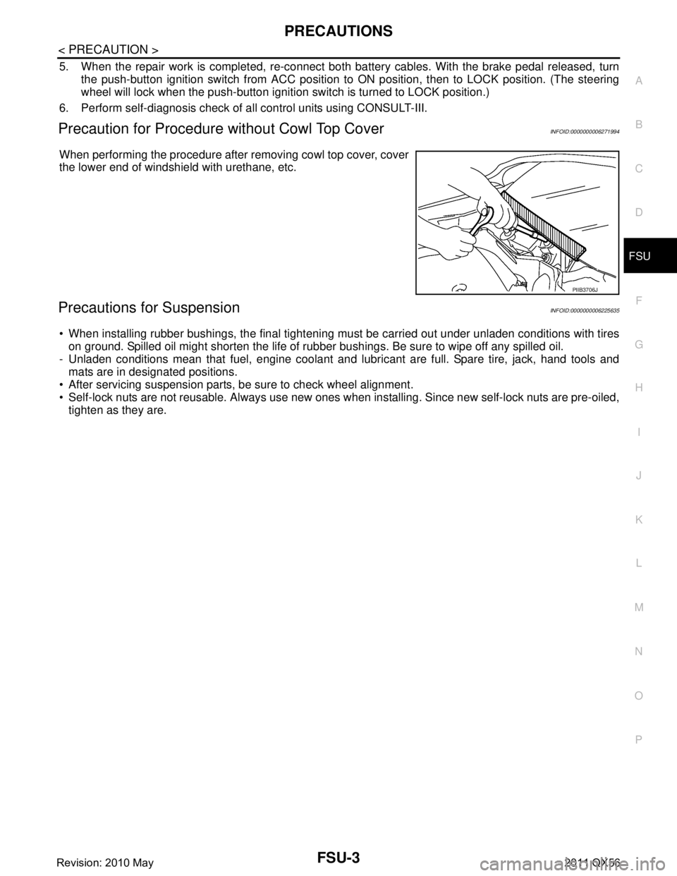
When performing the procedure after removing cowl top cover, cover
the lower end of windshield with urethane, etc.
Precautions for SuspensionINFOID:0000000006225635
When installing rubber bushings, the final tightening mu st be carried out under unladen conditions with tires
on ground. Spilled oil might shorten the life of rubb er bushings. Be sure to wipe off any spilled oil.
- Unladen conditions mean that fuel, engine coolant and l ubricant are full. Spare tire, jack, hand tools and
mats are in designated positions.
After servicing suspension parts, be sure to check wheel alignment.
Self-lock nuts are not reusable. Always use new ones w hen installing. Since new self-lock nuts are pre-oiled,
tighten as they are.
PIIB3706J
Revision: 2010 May2011 QX56
Page 2946 of 5598
FSU-4
< PREPARATION >
PREPARATION
PREPARATION
PREPARATION
Special Service ToolsINFOID:0000000006225636
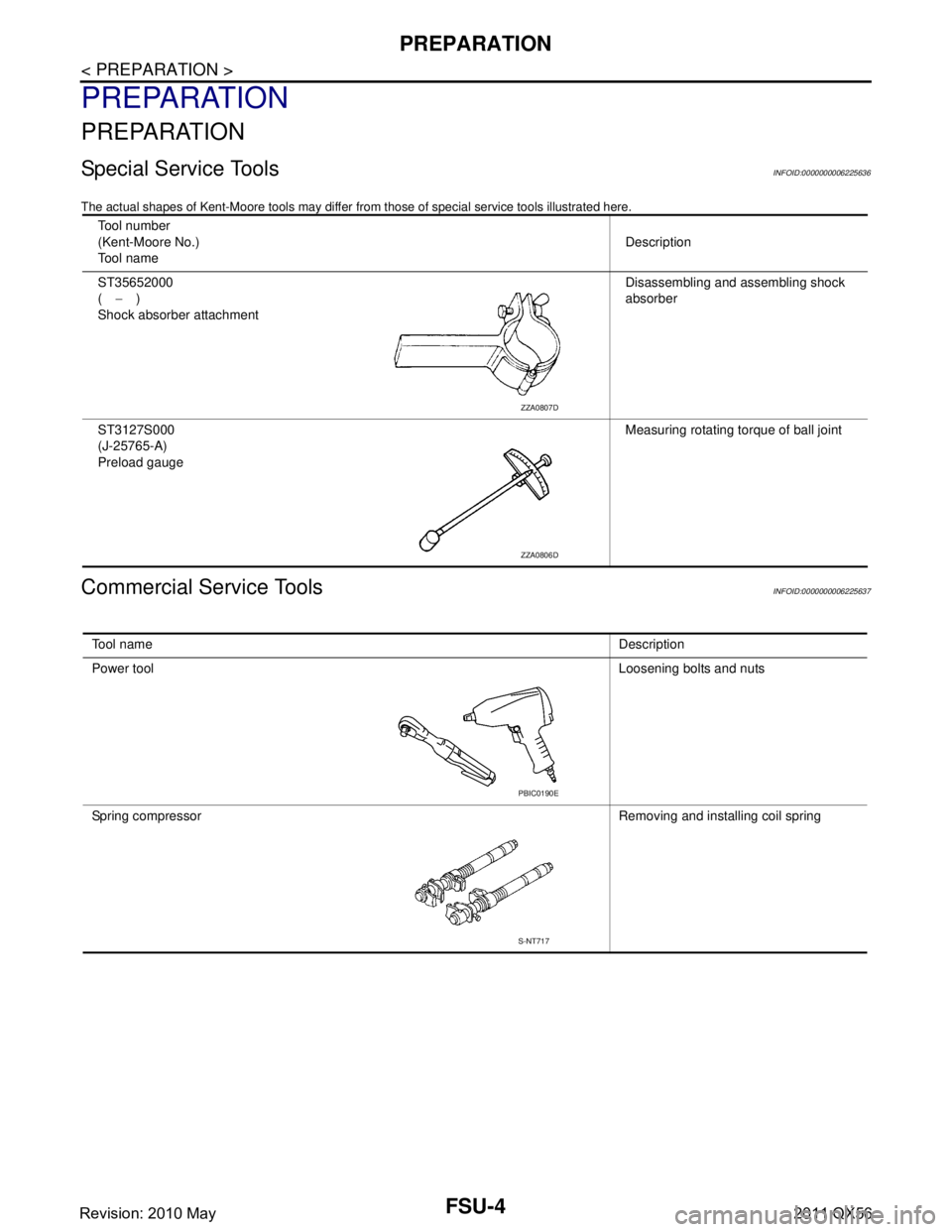
The actual shapes of Kent-Moore tools may differ from those of special service tools illustrated here.
Commercial Service ToolsINFOID:0000000006225637
Tool number
(Kent-Moore No.)
Tool name Description
ST35652000
( − )
Shock absorber attachment Disassembling and assembling shock
absorber
ST3127S000
(J-25765-A)
Preload gauge Measuring rotating torque of ball joint
ZZA0807D
ZZA0806D
Tool name
Description
Power tool Loosening bolts and nuts
Spring compressor Removing and installing coil spring
PBIC0190E
S-NT717
Revision: 2010 May2011 QX56
Page 2948 of 5598
FSU-6
< PERIODIC MAINTENANCE >
FRONT SUSPENSION ASSEMBLY
PERIODIC MAINTENANCE
FRONT SUSPENSION ASSEMBLY
InspectionINFOID:0000000006225639
MOUNTING INSPECTION
Check the mounting conditions (looseness, backlash) of each component and component conditions (wear,
damage) are normal.
BALL JOINT AXIAL END PLAY
1. Set front wheels in a straight-ahead position.
2. Measure axial end play by playing and moving up/dow n with iron bar or equivalent between lower link or
upper link and steering knuckle.
CAUTION:
Never depress brake pedal when measuring.
Never perform with tires on level ground.
Be careful not to damage ball joint boot. Never damage the installation position by applying
excessive force.
Shock absorber
Check for oil leakage, damage. Replace it if necessary. Axial end play : Refer to
FSU-21, "
Ball Joint".
Revision: 2010 May2011 QX56