2011 INFINITI QX56 oil
[x] Cancel search: oilPage 2684 of 5598
EM-122
< UNIT DISASSEMBLY AND ASSEMBLY >
CYLINDER BLOCK
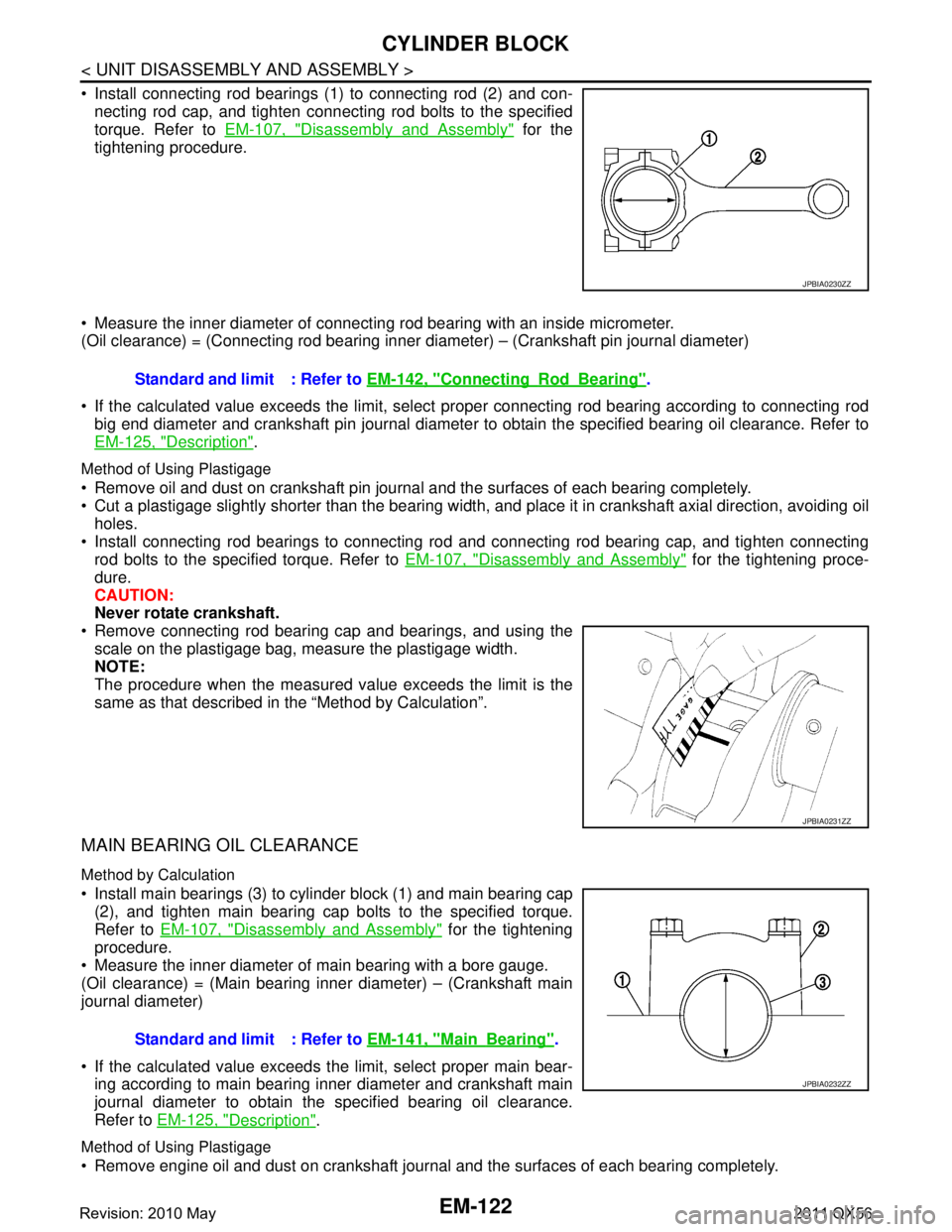
Install connecting rod bearings (1) to connecting rod (2) and con-necting rod cap, and tighten connecting rod bolts to the specified
torque. Refer to EM-107, "
Disassembly and Assembly" for the
tightening procedure.
Measure the inner diameter of connecting rod bearing with an inside micrometer.
(Oil clearance) = (Connecting rod bearing inner di ameter) – (Crankshaft pin journal diameter)
If the calculated value exceeds the limit, select proper connecting rod bearing according to connecting rod
big end diameter and crankshaft pin journal diameter to obtain the specified bearing oil clearance. Refer to
EM-125, "
Description".
Method of Using Plastigage
Remove oil and dust on crankshaft pin journal and the surfaces of each bearing completely.
Cut a plastigage slightly shorter than the bearing width, and place it in crankshaft axial direction, avoiding oil
holes.
Install connecting rod bearings to connecting rod and connecting rod bearing cap, and tighten connecting
rod bolts to the specified torque. Refer to EM-107, "
Disassembly and Assembly" for the tightening proce-
dure.
CAUTION:
Never rotate crankshaft.
Remove connecting rod bearing cap and bearings, and using the
scale on the plastigage bag, measure the plastigage width.
NOTE:
The procedure when the measured va lue exceeds the limit is the
same as that described in the “Method by Calculation”.
MAIN BEARING OIL CLEARANCE
Method by Calculation
Install main bearings (3) to cylinder block (1) and main bearing cap (2), and tighten main bearing cap bolts to the specified torque.
Refer to EM-107, "
Disassembly and Assembly" for the tightening
procedure.
Measure the inner diameter of main bearing with a bore gauge.
(Oil clearance) = (Main bearing inner diameter) – (Crankshaft main
journal diameter)
If the calculated value exceeds t he limit, select proper main bear-
ing according to main bearing inner diameter and crankshaft main
journal diameter to obtain the specified bearing oil clearance.
Refer to EM-125, "
Description".
Method of Using Plastigage
Remove engine oil and dust on crankshaft journal and the surfaces of each bearing completely.
JPBIA0230ZZ
Standard and limit : Refer to EM-142, "ConnectingRodBearing".
JPBIA0231ZZ
Standard and limit : Refer to EM-141, "MainBearing".
JPBIA0232ZZ
Revision: 2010 May2011 QX56
Page 2685 of 5598
CYLINDER BLOCKEM-123
< UNIT DISASSEMBLY AND ASSEMBLY >
C
DE
F
G H
I
J
K L
M A
EM
NP
O
Cut a plastigage slightly shorter than the bearing width,
and place it in crankshaft axial direction, avoiding oil
holes.
Install main bearing to cylinder block and main bearing cap, and tighten main bearing cap bolts with main
bearing cap to the specified torque. Refer to EM-107, "
Disassembly and Assembly" for the tightening proce-
dure.
CAUTION:
Never rotate crankshaft.
Remove main bearing cap and bearings, and using the scale on the plastigage bag, measure the plastigage width.
NOTE:
The procedure when the measured value exceeds the limit is the
same as that described in the “Method by Calculation”.
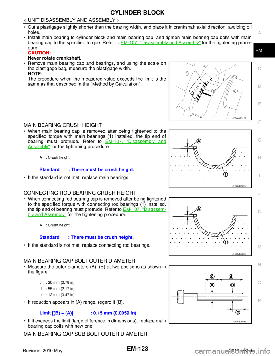
MAIN BEARING CRUSH HEIGHT
When main bearing cap is removed after being tightened to thespecified torque with main bearings (1) installed, the tip end of
bearing must protrude. Refer to EM-107, "
Disassembly and
Assembly" for the tightening procedure.
If the standard is not met, replace main bearings.
CONNECTING ROD BEARING CRUSH HEIGHT
When connecting rod bearing cap is removed after being tightened to the specified torque with connecting rod bearings (1) installed,
the tip end of bearing must protrude. Refer to EM-107, "
Disassem-
bly and Assembly" for the tightening procedure.
If the standard is not met, replace connecting rod bearings.
MAIN BEARING CAP BOLT OUTER DIAMETER
Measure the outer diameters (A), (B) at two positions as shown in
the figure.
If reduction appears in (A) range, regard it (B).
If it exceeds the limit (large difference in dimensions), replace main bearing cap bolts with new one.
MAIN BEARING CAP SUB BOLT OUTER DIAMETER
JPBIA0231ZZ
A : Crush height
Standard : There must be crush height.
JPBIA0233ZZ
A : Crush height
Standard : There must be crush height.
JPBIA0233ZZ
c : 20 mm (0.79 in)
d : 55 mm (2.17 in)
e : 12 mm (0.47 in)
Limit [(B) – (A)] : 0.15 mm (0.0059 in)
JPBIA2280ZZ
Revision: 2010 May2011 QX56
Page 2686 of 5598
EM-124
< UNIT DISASSEMBLY AND ASSEMBLY >
CYLINDER BLOCK
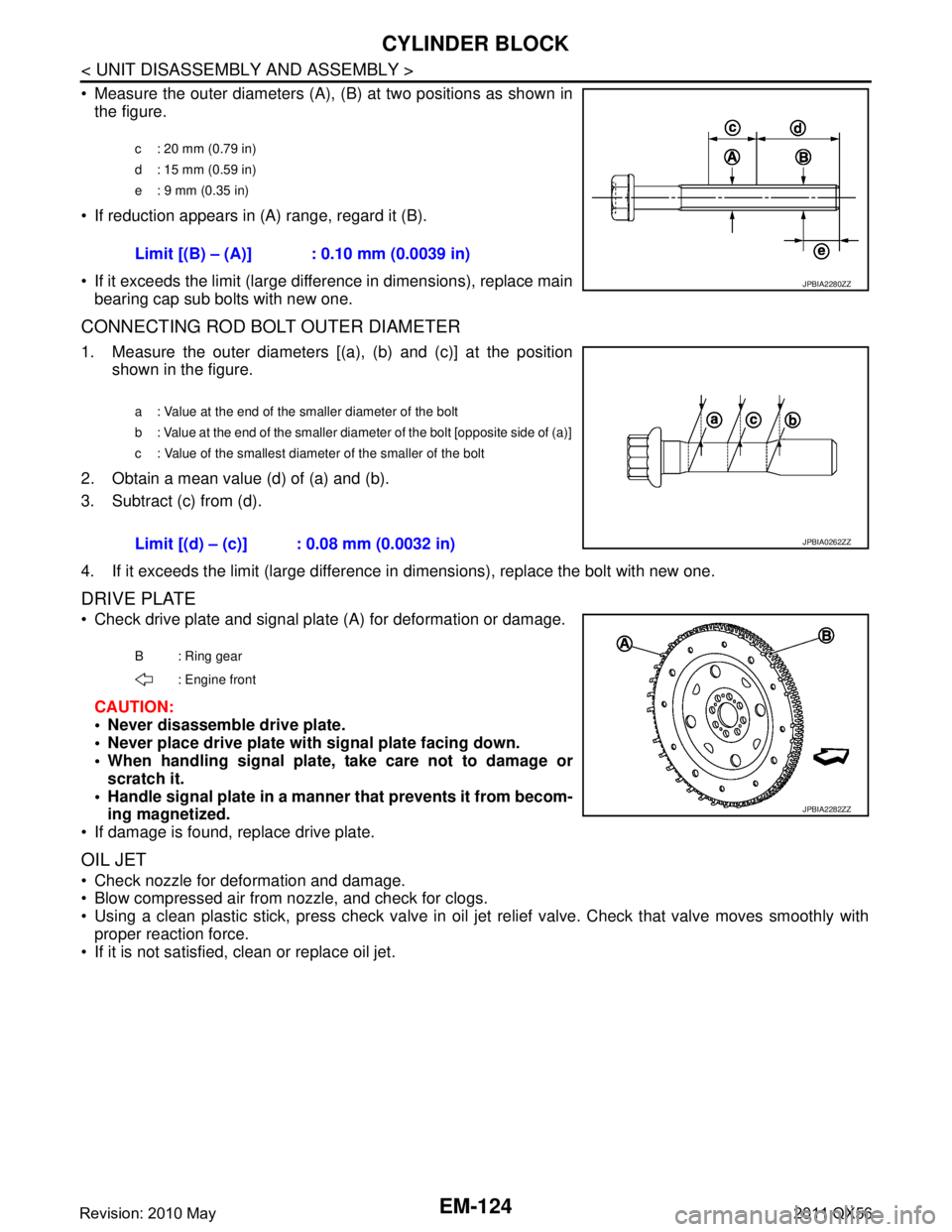
Measure the outer diameters (A), (B) at two positions as shown in
the figure.
If reduction appears in (A) range, regard it (B).
If it exceeds the limit (large difference in dimensions), replace main bearing cap sub bolts with new one.
CONNECTING ROD BOLT OUTER DIAMETER
1. Measure the outer diameters [(a), (b) and (c)] at the position shown in the figure.
2. Obtain a mean value (d) of (a) and (b).
3. Subtract (c) from (d).
4. If it exceeds the limit (large difference in dimensions), replace the bolt with new one.
DRIVE PLATE
Check drive plate and signal plate (A) for deformation or damage.
CAUTION:
Never disassemble drive plate.
Never place drive plate with signal plate facing down.
When handling signal plate, take care not to damage or scratch it.
Handle signal plate in a manner that prevents it from becom-
ing magnetized.
If damage is found, replace drive plate.
OIL JET
Check nozzle for deformation and damage.
Blow compressed air from nozzle, and check for clogs.
Using a clean plastic stick, press check valve in oil je t relief valve. Check that valve moves smoothly with
proper reaction force.
If it is not satisfied, clean or replace oil jet.
c : 20 mm (0.79 in)
d : 15 mm (0.59 in)
e : 9 mm (0.35 in)
Limit [(B) – (A)] : 0.10 mm (0.0039 in)
JPBIA2280ZZ
a : Value at the end of the smaller diameter of the bolt
b : Value at the end of the smaller diameter of the bolt [opposite side of (a)]
c : Value of the smallest diameter of the smaller of the bolt
Limit [(d) – (c)] : 0.08 mm (0.0032 in)JPBIA0262ZZ
B : Ring gear
: Engine front
JPBIA2282ZZ
Revision: 2010 May2011 QX56
Page 2689 of 5598
HOW TO SELECT PISTON AND BEARINGEM-127
< UNIT DISASSEMBLY AND ASSEMBLY >
C
DE
F
G H
I
J
K L
M A
EM
NP
O
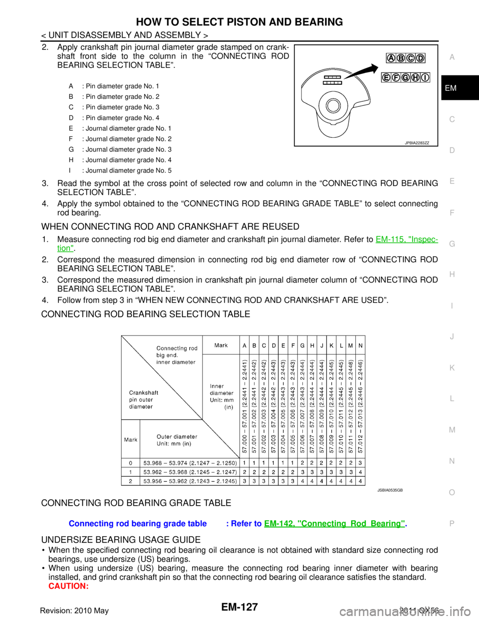
2. Apply crankshaft pin journal
diameter grade stamped on crank-
shaft front side to the column in the “CONNECTING ROD
BEARING SELECTION TABLE”.
3. Read the symbol at the cross point of select ed row and column in the “CONNECTING ROD BEARING
SELECTION TABLE”.
4. Apply the symbol obtained to the “CONNECTING ROD BEARING GRADE TABLE” to select connecting
rod bearing.
WHEN CONNECTING ROD AND CRANKSHAFT ARE REUSED
1. Measure connecting rod big end diameter and crankshaft pin journal diameter. Refer to EM-115, "Inspec-
tion".
2. Correspond the measured dimension in connecting rod big end diameter row of “CONNECTING ROD
BEARING SELECTION TABLE”.
3. Correspond the measured dimension in crankshaft pi n journal diameter column of “CONNECTING ROD
BEARING SELECTION TABLE”.
4. Follow from step 3 in “WHEN NEW CONNECTING ROD AND CRANKSHAFT ARE USED”.
CONNECTING ROD BEARING SELECTION TABLE
CONNECTING ROD BEARING GRADE TABLE
UNDERSIZE BEARING USAGE GUIDE
When the specified connecting rod bearing oil clearance is not obtained with standard size connecting rod bearings, use undersize (US) bearings.
When using undersize (US) bearing, measure the connecting rod bearing inner diameter with bearing
installed, and grind crankshaft pin so that the c onnecting rod bearing oil clearance satisfies the standard.
CAUTION:
A : Pin diameter grade No. 1
B : Pin diameter grade No. 2
C : Pin diameter grade No. 3
D : Pin diameter grade No. 4
E : Journal diameter grade No. 1
F : Journal diameter grade No. 2
G : Journal diameter grade No. 3
H : Journal diameter grade No. 4
I : Journal diameter grade No. 5
JPBIA2283ZZ
JSBIA0535GB
Connecting rod bearing grade table : Refer to EM-142, "ConnectingRodBearing".
Revision: 2010 May2011 QX56
Page 2692 of 5598
EM-130
< UNIT DISASSEMBLY AND ASSEMBLY >
HOW TO SELECT PISTON AND BEARING
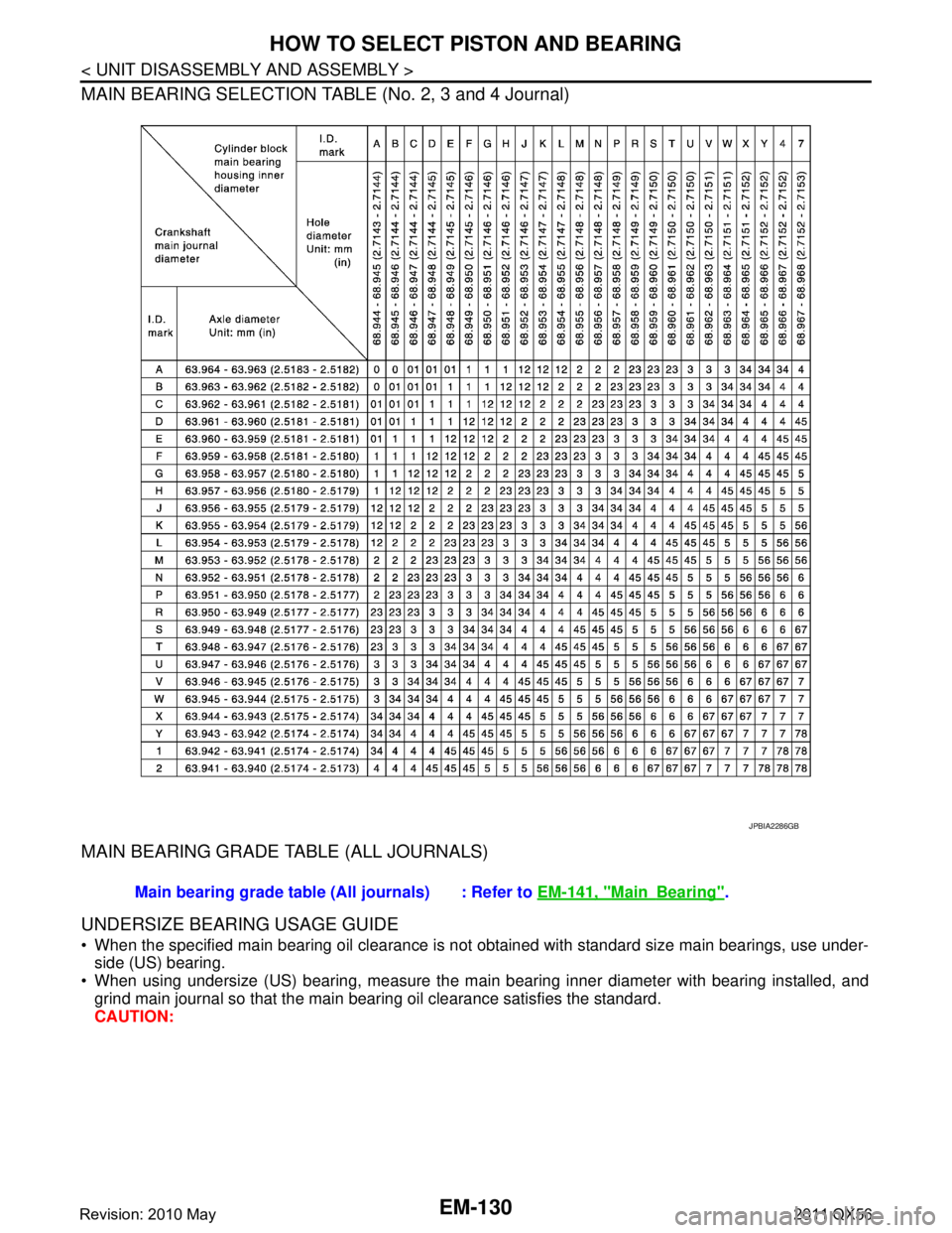
MAIN BEARING SELECTION TABLE (No. 2, 3 and 4 Journal)
MAIN BEARING GRADE TABLE (ALL JOURNALS)
UNDERSIZE BEARING USAGE GUIDE
When the specified main bearing oil clearance is not obtained with standard size main bearings, use under-side (US) bearing.
When using undersize (US) bearing, measure the main bearing inner diameter with bearing installed, and
grind main journal so that the main bearing oil clearance satisfies the standard.
CAUTION:
JPBIA2286GB
Main bearing grade table (A ll journals) : Refer to EM-141, "MainBearing".
Revision: 2010 May2011 QX56
Page 2694 of 5598
EM-132
< SERVICE DATA AND SPECIFICATIONS (SDS)
SERVICE DATA AND SPECIFICATIONS (SDS)
SERVICE DATA AND SPECIFICATIONS (SDS)
SERVICE DATA AND SPECIFICATIONS (SDS)
General SpecificationINFOID:0000000006289589
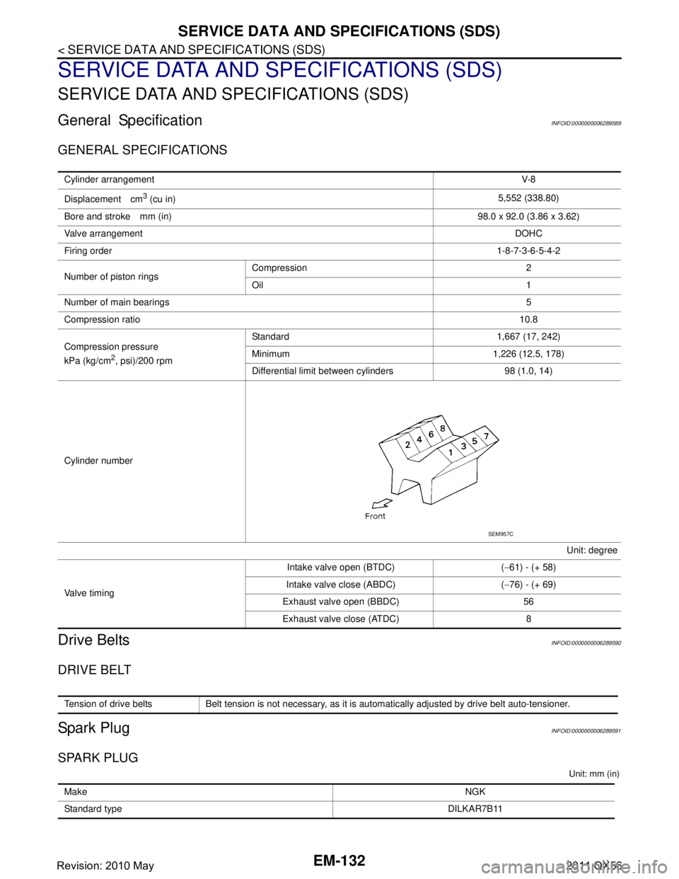
GENERAL SPECIFICATIONS
Drive BeltsINFOID:0000000006289590
DRIVE BELT
Spark PlugINFOID:0000000006289591
SPARK PLUG
Unit: mm (in)
Cylinder arrangementV-8
Displacement cm
3 (cu in) 5,552 (338.80)
Bore and stroke mm (in) 98.0 x 92.0 (3.86 x 3.62)
Valve arrangement DOHC
Firing order 1-8-7-3-6-5-4-2
Number of piston rings Compression 2
Oil 1
Number of main bearings 5
Compression ratio 10.8
Compression pressure
kPa (kg/cm
2, psi)/200 rpm Standard 1,667 (17, 242)
Minimum 1,226 (12.5, 178)
Differential limit between cylinders 98 (1.0, 14)
Cylinder number Unit: degree
Valve timing Intake valve open (BTDC) (
−61) - (+ 58)
Intake valve close (ABDC) ( −76) - (+ 69)
Exhaust valve open (BBDC) 56 Exhaust valve close (ATDC) 8
SEM957C
Tension of drive belts Belt tension is not necessary, as it is automatically adjusted by drive belt auto-tensioner.
Make NGK
Standard type DILKAR7B11
Revision: 2010 May2011 QX56
Page 2695 of 5598
SERVICE DATA AND SPECIFICATIONS (SDS)
EM-133
< SERVICE DATA AND SPECIFICATIONS (SDS)
C
D E
F
G H
I
J
K L
M A
EM
NP
O
Exhaust ManifoldINFOID:0000000006289592
EXHAUST MANIFOLD
Unit: mm (in)
CamshaftINFOID:0000000006289593
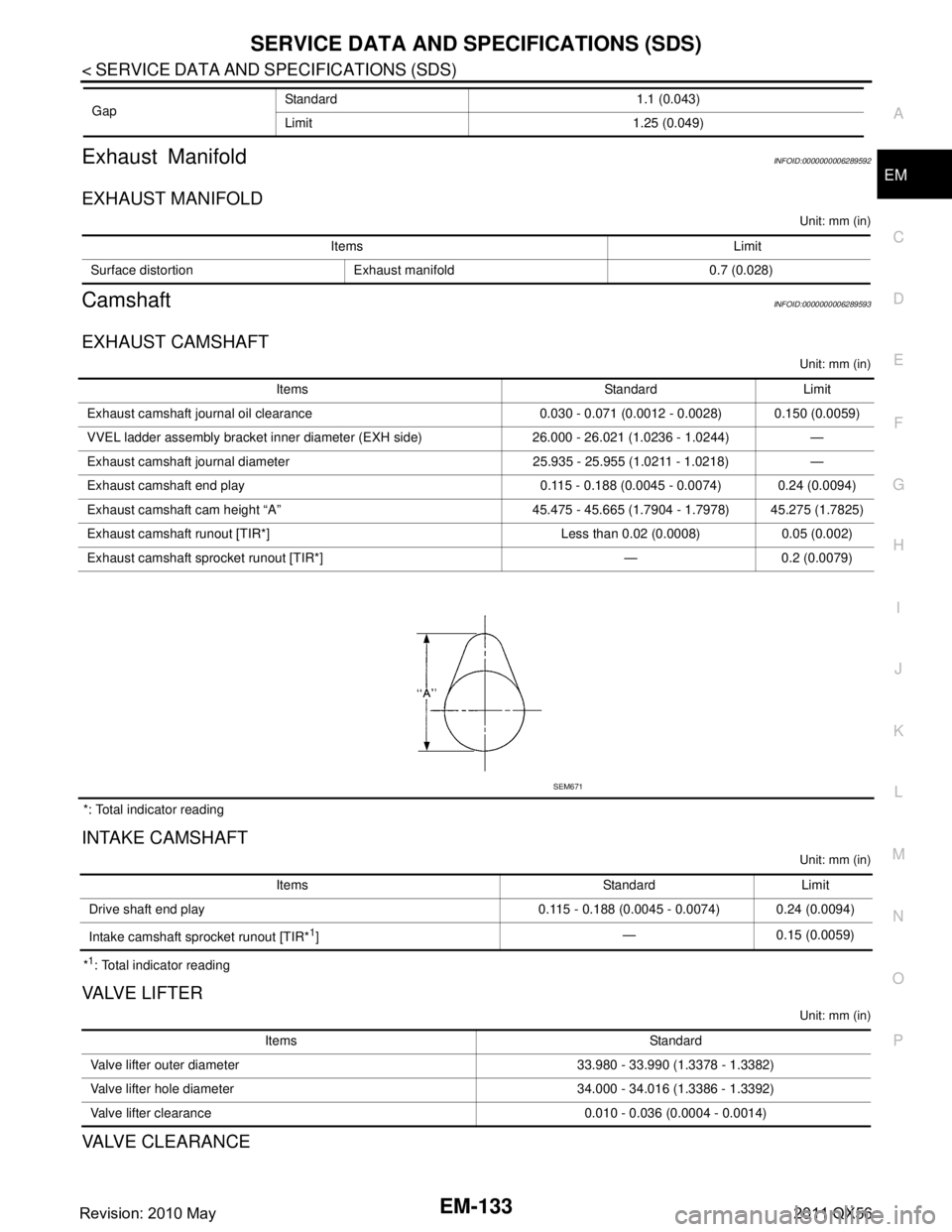
EXHAUST CAMSHAFT
Unit: mm (in)
*: Total indicator reading
INTAKE CAMSHAFT
Unit: mm (in)
*1: Total indicator reading
VA LV E L I F T E R
Unit: mm (in)
VALVE CLEARANCE
Gap
Standard 1.1 (0.043)
Limit 1.25 (0.049)
Items Limit
Surface distortion Exhaust manifold 0.7 (0.028)
Items Standard Limit
Exhaust camshaft journal oil clearance 0.030 - 0.071 (0.0012 - 0.0028) 0.150 (0.0059)
VVEL ladder asse mbly bracket inner diameter (EXH side) 26.000 - 26.021 (1.0236 - 1.0244) —
Exhaust camshaft journal diameter 25.935 - 25.955 (1.0211 - 1.0218) —
Exhaust camshaft end play 0.115 - 0.188 (0.0045 - 0.0074) 0.24 (0.0094)
Exhaust camshaft cam height “A” 45.475 - 45.665 (1.7904 - 1.7978) 45.275 (1.7825)
Exhaust camshaft runout [TIR*] Less than 0.02 (0.0008) 0.05 (0.002)
Exhaust camshaft sprocket runout [TIR*] — 0.2 (0.0079)
SEM671
Items Standard Limit
Drive shaft end play 0.115 - 0.188 (0.0045 - 0.0074) 0.24 (0.0094)
Intake camshaft sprocket runout [TIR*
1] — 0.15 (0.0059)
Items Standard
Valve lifter outer diameter 33.980 - 33.990 (1.3378 - 1.3382)
Valve lifter hole diameter 34.000 - 34.016 (1.3386 - 1.3392)
Valve lifter clearance 0.010 - 0.036 (0.0004 - 0.0014)
Revision: 2010 May2011 QX56
Page 2700 of 5598
EM-138
< SERVICE DATA AND SPECIFICATIONS (SDS)
SERVICE DATA AND SPECIFICATIONS (SDS)
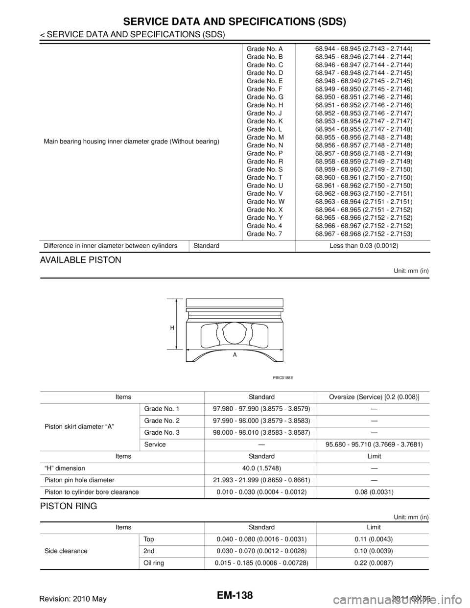
AVAILABLE PISTON
Unit: mm (in)
PISTON RING
Unit: mm (in)
Main bearing housing inner diameter grade (Without bearing)Grade No. A
Grade No. B
Grade No. C
Grade No. D
Grade No. E
Grade No. F
Grade No. G
Grade No. H
Grade No. J
Grade No. K
Grade No. L
Grade No. M
Grade No. N
Grade No. P
Grade No. R
Grade No. S
Grade No. T
Grade No. U
Grade No. V
Grade No. W
Grade No. X
Grade No. Y
Grade No. 4
Grade No. 768.944 - 68.945 (2.7143 - 2.7144)
68.945 - 68.946 (2.7144 - 2.7144)
68.946 - 68.947 (2.7144 - 2.7144)
68.947 - 68.948 (2.7144 - 2.7145)
68.948 - 68.949 (2.7145 - 2.7145)
68.949 - 68.950 (2.7145 - 2.7146)
68.950 - 68.951 (2.7146 - 2.7146)
68.951 - 68.952 (2.7146 - 2.7146)
68.952 - 68.953 (2.7146 - 2.7147)
68.953 - 68.954 (2.7147 - 2.7147)
68.954 - 68.955 (2.7147 - 2.7148)
68.955 - 68.956 (2.7148 - 2.7148)
68.956 - 68.957 (2.7148 - 2.7148)
68.957 - 68.958 (2.7148 - 2.7149)
68.958 - 68.959 (2.7149 - 2.7149)
68.959 - 68.960 (2.7149 - 2.7150)
68.960 - 68.961 (2.7150 - 2.7150)
68.961 - 68.962 (2.7150 - 2.7150)
68.962 - 68.963 (2.7150 - 2.7151)
68.963 - 68.964 (2.7151 - 2.7151)
68.964 - 68.965 (2.7151 - 2.7152)
68.965 - 68.966 (2.7152 - 2.7152)
68.966 - 68.967 (2.7152 - 2.7152)
68.967 - 68.968 (2.7152 - 2.7153)
Difference in inner diameter between cylinders Standard Less than 0.03 (0.0012)
Items Standard Oversize (S ervice) [0.2 (0.008)]
Piston skirt diameter “A” Grade No. 1 97.980 - 97.990 (3.8575 - 3.8579) —
Grade No. 2 97.990 - 98.000 (3.8579 - 3.8583) —
Grade No. 3 98.000 - 98.010 (3.8583 - 3.8587) —
Service — 95.680 - 95.710 (3.7669 - 3.7681)
Items Standard Limit
“H” dimension 40.0 (1.5748) —
Piston pin hole diameter 21.993 - 21.999 (0.8659 - 0.8661) —
Piston to cylinder bore clearance 0.010 - 0.030 (0.0004 - 0.0012) 0.08 (0.0031)
PBIC0188E
Items Standard Limit
Side clearance Top 0.040 - 0.080 (0.0016 - 0.0031) 0.11 (0.0043)
2nd 0.030 - 0.070 (0.0012 - 0.0028) 0.10 (0.0039)
Oil ring 0.015 - 0.185 (0.0006 - 0.00728) 0.22 (0.0087)
Revision: 2010 May2011 QX56