2011 INFINITI QX56 fuel pump
[x] Cancel search: fuel pumpPage 2095 of 5598
DIAGNOSIS SYSTEM (ECM)EC-71
< SYSTEM DESCRIPTION > [VK56VD]
C
D
E
F
G H
I
J
K L
M A
EC
NP
O
*: Leaving cooling fan OFF with CONSULT-III while engine is running may cause the engine to overheat.
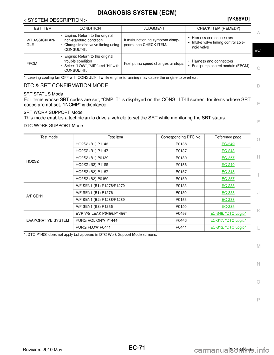
DTC & SRT CONFIRMATION MODE
SRT STATUS Mode
For items whose SRT codes are set, “CMPLT” is disp
layed on the CONSULT-III screen; for items whose SRT
codes are not set, “INCMP” is displayed.
SRT WORK SUPPORT Mode
This mode enables a technician to drive a vehicle to set the SRT while monitoring the SRT status.
DTC WORK SUPPORT Mode
*: DTC P1456 does not apply but appears in DTC Work Support Mode screens. V/T ASSIGN AN-
GLE
Engine: Return to the original
non-standard condition
Change intake valve timing using CONSULT-III. If malfunctioning symptom disap-
pears, see CHECK ITEM.
Harness and connectors
Intake valve timing control sole-
noid valve
FPCM Engine: Return to the original
trouble condition
Select “LOW”, “MID” and “HI” with CONSULT-III. Fuel pump speed changes or stops.
Harness and connectors
Fuel pump control module (FPCM)
TEST ITEM CONDITION JUDGMENT CHECK ITEM (REMEDY)
Test mode Test item Corresponding DTC No. Reference page
HO2S2 HO2S2 (B1) P1146 P0138
EC-249
HO2S2 (B1) P1147 P0137EC-243
HO2S2 (B1) P0139 P0139EC-257
HO2S2 (B2) P1166 P0158EC-249
HO2S2 (B2) P1167 P0157EC-243
HO2S2 (B2) P0159 P0159EC-257
A/F SEN1A/F SEN1 (B1) P1278/P1279 P0133
EC-238A/F SEN1 (B1) P1276 P0130EC-228
A/F SEN1 (B2) P1288/P1289 P0153EC-238
A/F SEN1 (B2) P1286 P0150EC-228
EVAPORATIVE SYSTEMEVP V/S LEAK P0456/P1456* P0456
EC-346, "
DTC Logic"
PURG VOL CN/V P1444 P0443EC-317, "DTC Logic"
PURG FLOW P0441 P0441EC-312, "DTC Logic"
Revision: 2010 May2011 QX56
Page 2100 of 5598
EC-76
< ECU DIAGNOSIS INFORMATION >[VK56VD]
ECM
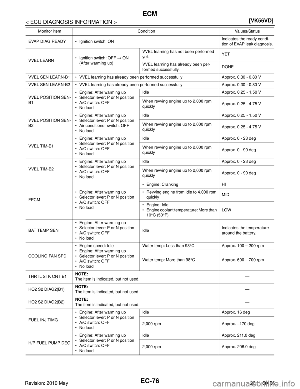
EVAP DIAG READY Ignition switch: ON Indicates the ready condi-
tion of EVAP leak diagnosis.
VVEL LEARN Ignition switch: OFF
→ ON
(After warming up) VVEL learning has no
t been performed
yet. YET
VVEL learning has already been per-
formed successfully. DONE
VVEL SEN LEARN-B1 VVEL learning has already been performed successfully Approx. 0.30 - 0.80 V
VVEL SEN LEARN-B2 VVEL learning has already been performed successfully Approx. 0.30 - 0.80 V
VVEL POSITION SEN-
B1 Engine: After warming up
Selector lever: P or N position
A/C switch: OFF
No load Idle Approx. 0.25 - 1.50 V
When revving engine up to 2,000 rpm
quickly
Approx. 0.25 - 4.75 V
VVEL POSITION SEN-
B2 Engine: After warming up
Selector lever: P or N position
Air conditioner switch: OFF
No load Idle Approx. 0.25 - 1.50 V
When revving engine up to 2,000 rpm
quickly
Approx. 0.25 - 4.75 V
VVEL TIM-B1 Engine: After warming up
Selector lever: P or N position
A/C switch: OFF
No load Idle Approx. 0 - 23 deg
When revving engine up to 2,000 rpm
quickly
Approx. 0 - 90 deg
VVEL TIM-B2 Engine: After warming up
Selector lever: P or N position
A/C switch: OFF
No load Idle Approx. 0 - 23 deg
When revving engine up to 2,000 rpm
quickly
Approx. 0 - 90 deg
FPCM Engine: After warming up
Selector lever: P or N position
A/C switch: OFF
No load Engine: Cranking HI
Revving engine from idle to 4,000 rpm
quickly MID
Engine: Idle
Engine coolant temperature: More than 10 °C (50 °F) LOW
BAT TEMP SEN Engine: After warming up
Selector lever: P or N position
A/C switch: OFF
No load Idle
Indicates the temperature
around the battery.
COOLING FAN SPD Engine speed: Idle
Engine: After warming up
Selector lever: P or N position
A/C switch: OFF
No load Water temp: Less than 98
°C Approx. 100 – 200 rpm
Water temp: More than 98 °C Approx. 600 – 700 rpm
THRTL STK CNT B1 NOTE:
The item is indicated, but not used. —
HO2 S2 DIAG2(B1) NOTE:
The item is indicated, but not used.
—
HO2 S2 DIAG2(B2) NOTE:
The item is indicated, but not used. —
FUEL INJ TIMG Engine: After warming up
Selector lever: P or N position
A/C switch: OFF
No load Idle Approx. 16 deg
2,000 rpm Approx.
−170 deg
H/P FUEL PUMP DEG Engine: After warming up
Selector lever: P or N position
A/C switch: OFF
No load Idle Approx. 211.0 deg
2,000 rpm Approx. 206.0 deg
Monitor Item Condition Values/Status
Revision: 2010 May2011 QX56
Page 2101 of 5598
ECM
EC-77
< ECU DIAGNOSIS INFORMATION > [VK56VD]
C
D
E
F
G H
I
J
K L
M A
EC
NP
O
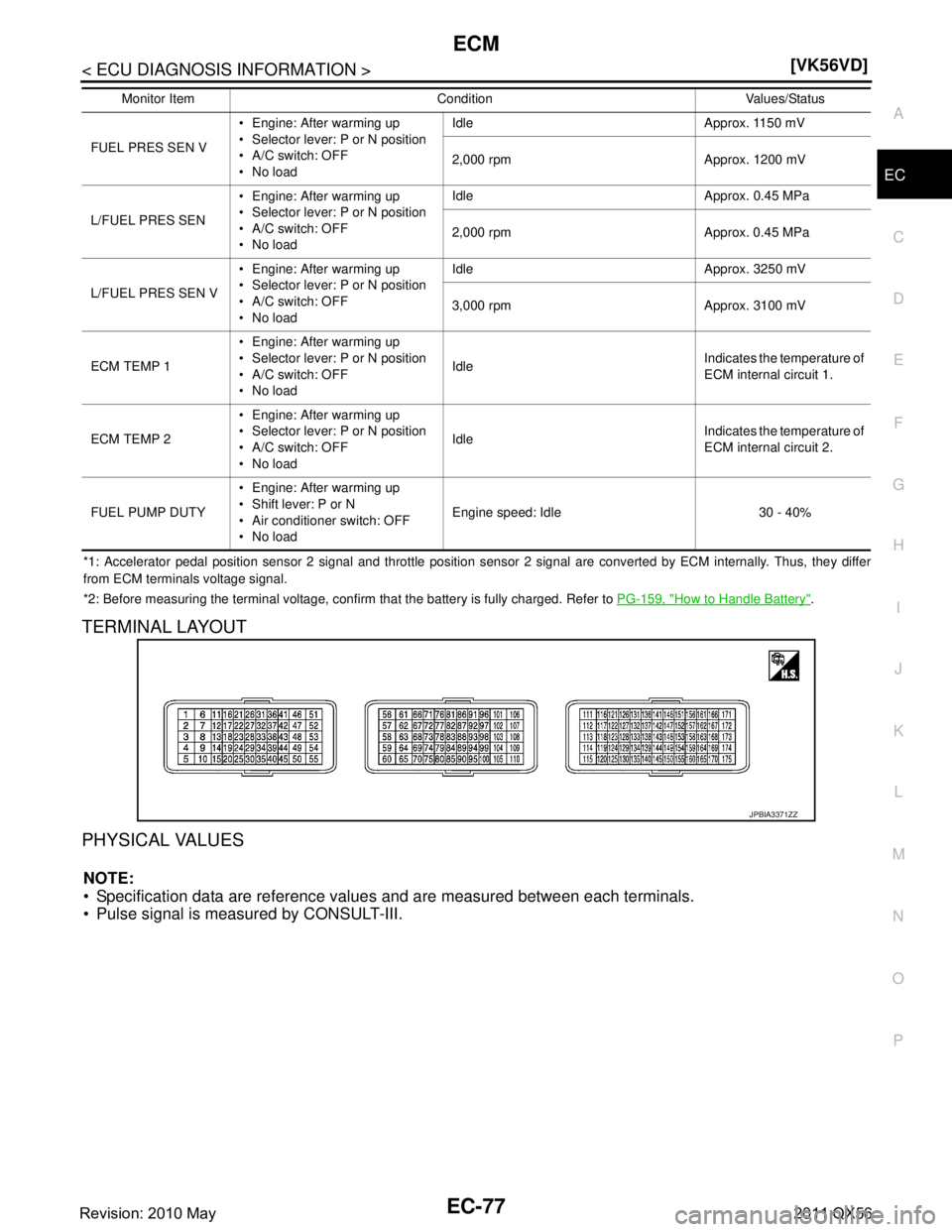
*1: Accelerator pedal position sensor 2 signal and throttle position sensor 2 signal are converted by ECM internally. Thus, the
y differ
from ECM terminals voltage signal.
*2: Before measuring the terminal voltage, confirm that the battery is fully charged. Refer to PG-159, "
How to Handle Battery".
TERMINAL LAYOUT
PHYSICAL VALUES
NOTE:
Specification data are reference values and are measured between each terminals.
Pulse signal is measured by CONSULT-III.
FUEL PRES SEN V Engine: After warming up
Selector lever: P or N position
A/C switch: OFF
No load Idle Approx. 1150 mV
2,000 rpm Approx. 1200 mV
L/FUEL PRES SEN Engine: After warming up
Selector lever: P or N position
A/C switch: OFF
No load Idle Approx. 0.45 MPa
2,000 rpm Approx. 0.45 MPa
L/FUEL PRES SEN V Engine: After warming up
Selector lever: P or N position
A/C switch: OFF
No load Idle Approx. 3250 mV
3,000 rpm Approx. 3100 mV
ECM TEMP 1 Engine: After warming up
Selector lever: P or N position
A/C switch: OFF
No load Idle
Indicates the temperature of
ECM internal circuit 1.
ECM TEMP 2 Engine: After warming up
Selector lever: P or N position
A/C switch: OFF
No load Idle
Indicates the temperature of
ECM internal circuit 2.
FUEL PUMP DUTY Engine: After warming up
Shift lever: P or N
Air conditioner switch: OFF
No load Engine speed: Idle 30 - 40%
Monitor Item Condition Values/Status
JPBIA3371ZZ
Revision: 2010 May2011 QX56
Page 2112 of 5598
EC-88
< ECU DIAGNOSIS INFORMATION >[VK56VD]
ECM
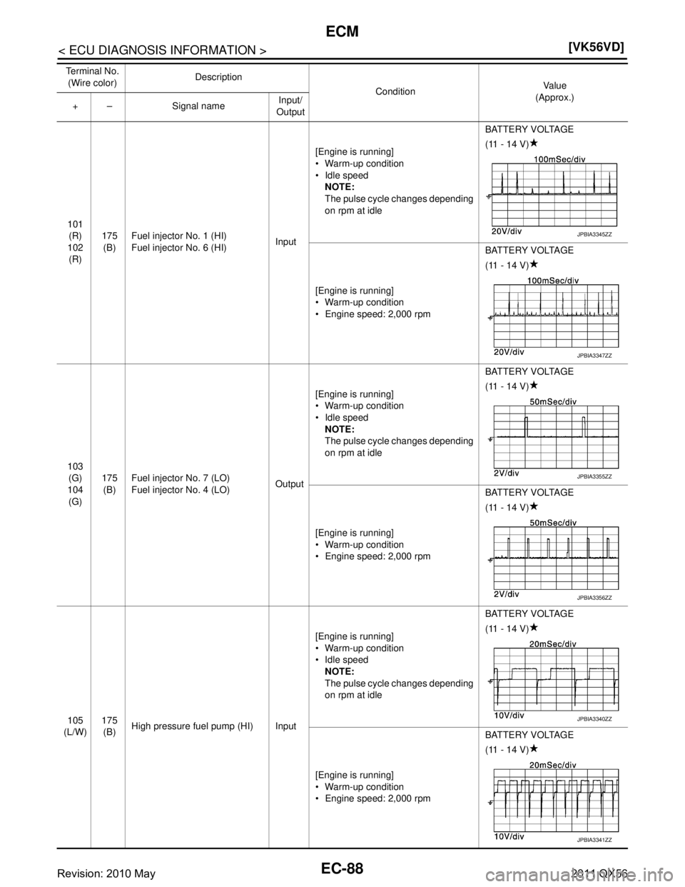
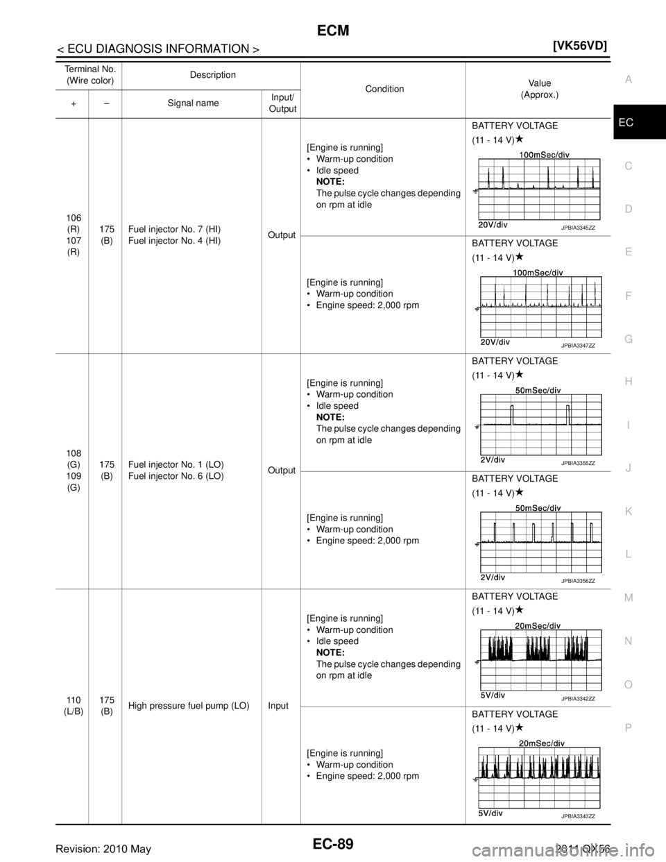
101
(R)
102 (R) 175
(B) Fuel injector No. 1 (HI)
Fuel injector No. 6 (HI)
Input[Engine is running]
Warm-up condition
Idle speed
NOTE:
The pulse cycle changes depending
on rpm at idle BATTERY VOLTAGE
(11 - 14 V)
[Engine is running]
Warm-up condition
Engine speed: 2,000 rpm BATTERY VOLTAGE
(11 - 14 V)
103 (G)
104 (G) 175
(B) Fuel injector No. 7 (LO)
Fuel injector No. 4 (LO)
Output[Engine is running]
Warm-up condition
Idle speed
NOTE:
The pulse cycle changes depending
on rpm at idle BATTERY VOLTAGE
(11 - 14 V)
[Engine is running]
Warm-up condition
Engine speed: 2,000 rpm BATTERY VOLTAGE
(11 - 14 V)
105
(L/W) 175
(B) High pressure fuel pump (HI) Input [Engine is running]
Warm-up condition
Idle speed
NOTE:
The pulse cycle changes depending
on rpm at idle BATTERY VOLTAGE
(11 - 14 V)
[Engine is running]
Warm-up condition
Engine speed: 2,000 rpm BATTERY VOLTAGE
(11 - 14 V)
Te r m i n a l N o .
(Wire color) Description
ConditionVa l u e
(Approx.)
+ – Signal name Input/
OutputJPBIA3345ZZ
JPBIA3347ZZ
JPBIA3355ZZ
JPBIA3356ZZ
JPBIA3340ZZ
JPBIA3341ZZ
Revision: 2010 May2011 QX56
Page 2113 of 5598
ECM
EC-89
< ECU DIAGNOSIS INFORMATION > [VK56VD]
C
D
E
F
G H
I
J
K L
M A
EC
NP
O
106
(R)
107 (R) 175
(B) Fuel injector No. 7 (HI)
Fuel injector No. 4 (HI)
Output[Engine is running]
Warm-up condition
Idle speed
NOTE:
The pulse cycle changes depending
on rpm at idle BATTERY VOLTAGE
(11 - 14 V)
[Engine is running]
Warm-up condition
Engine speed: 2,000 rpm BATTERY VOLTAGE
(11 - 14 V)
108 (G)
109 (G) 175
(B) Fuel injector No. 1 (LO)
Fuel injector No. 6 (LO)
Output[Engine is running]
Warm-up condition
Idle speed
NOTE:
The pulse cycle changes depending
on rpm at idle BATTERY VOLTAGE
(11 - 14 V)
[Engine is running]
Warm-up condition
Engine speed: 2,000 rpm BATTERY VOLTAGE
(11 - 14 V)
11 0
(L/B) 175
(B) High pressure fuel pump (LO) Input [Engine is running]
Warm-up condition
Idle speed
NOTE:
The pulse cycle changes depending
on rpm at idle BATTERY VOLTAGE
(11 - 14 V)
[Engine is running]
Warm-up condition
Engine speed: 2,000 rpm BATTERY VOLTAGE
(11 - 14 V)
Te r m i n a l N o .
(Wire color) Description
ConditionVa l u e
(Approx.)
+ – Signal name Input/
OutputJPBIA3345ZZ
JPBIA3347ZZ
JPBIA3355ZZ
JPBIA3356ZZ
JPBIA3342ZZ
JPBIA3343ZZ
Revision: 2010 May2011 QX56
Page 2114 of 5598
EC-90
< ECU DIAGNOSIS INFORMATION >[VK56VD]
ECM
111
(R) 175
(B) Fuel injector driver power supply Input [Ignition switch: ON]
BATTERY VOLTAGE
(11 - 14 V)
11 2
(SB) 175
(B) Fuel injector driver power supply Input [Ignition switch: ON] BATTERY VOLTAGE
(11 - 14 V)
11 4 (B) — ECM ground — — —
11 5 (B) — ECM ground — — —
120 (Y) 175
(B) EVAP canister vent control valve Output [Ignition switch: ON] BATTERY VOLTAGE
(11 - 14 V)
122
(BR/ W) 175
(B) VVEL actuator motor relay abort
signal (VVEL control module)
Input [Ignition switch: ON] 0 V
123
(V/R) 175
(B) Throttle control mo
tor relay Output [Ignition switch: ON
→ OFF] 0 - 1.0 V
↓
BATTERY VOLTAGE
(11 - 14 V)
↓
0 V
[Ignition switch: ON] 0 - 1.0 V
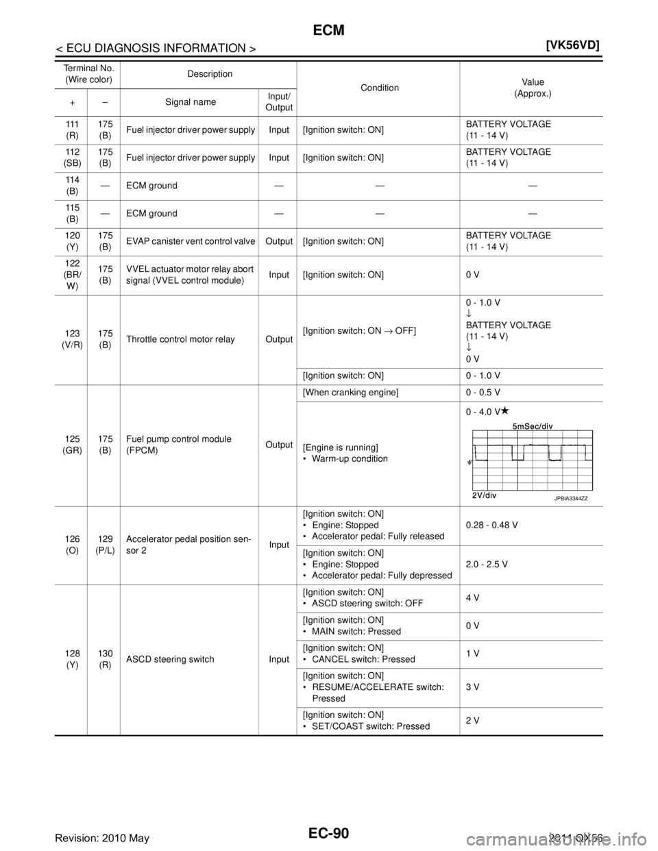
125
(GR) 175
(B) Fuel pump control module
(FPCM)
Output[When cranking engine] 0 - 0.5 V
[Engine is running]
Warm-up condition
0 - 4.0 V
126 (O) 129
(P/L) Accelerator pedal position sen-
sor 2
Input[Ignition switch: ON]
Engine: Stopped
Accelerator pedal: Fully released
0.28 - 0.48 V
[Ignition switch: ON]
Engine: Stopped
Accelerator pedal: Fully depressed 2.0 - 2.5 V
128 (Y) 130
(R) ASCD steering switch Input [Ignition switch: ON]
ASCD steering switch: OFF
4 V
[Ignition switch: ON]
MAIN switch: Pressed 0 V
[Ignition switch: ON]
CANCEL switch: Pressed 1 V
[Ignition switch: ON]
RESUME/ACCELERATE switch: Pressed 3 V
[Ignition switch: ON]
SET/COAST switch: Pressed 2 V
Te r m i n a l N o .
(Wire color) Description
ConditionVa l u e
(Approx.)
+ – Signal name Input/
Output
JPBIA3344ZZ
Revision: 2010 May2011 QX56
Page 2116 of 5598
EC-92
< ECU DIAGNOSIS INFORMATION >[VK56VD]
ECM
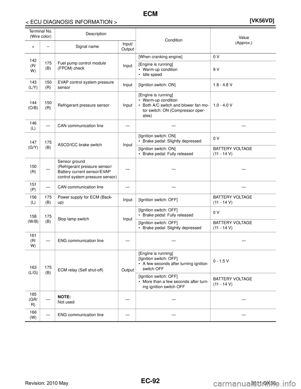
142
(R/W) 175
(B) Fuel pump control module
(FPCM) check
Input[When cranking engine] 0 V
[Engine is running]
Warm-up condition
Idle speed
9 V
143
(L/Y) 150
(R) EVAP control system pressure
sensor
Input [Ignition switch: ON] 1.8 - 4.8 V
144
(O/B) 150
(R) Refrigerant pressure sensor Input [Engine is running]
Warm-up condition
Both A/C switch and blower fan mo-
tor switch: ON (Compressor oper-
ates) 1.0 - 4.0 V
146 (L) — CAN communication line — — —
147
(G/Y) 175
(B) ASCD/ICC brake switch Input [Ignition switch: ON]
Brake pedal: Slightly depressed
0 V
[Ignition switch: ON]
Brake pedal: Fully released BATTERY VOLTAGE
(11 - 14 V)
150 (R) —Sensor ground
(Refrigerant pressure sensor/
Battery current sensor/EVAP
control system pressure sensor) —— —
151 (P) — CAN communication line — — —
156 (L) 175
(B) Power supply
for ECM (Back-
up) Input [Ignition switch: OFF] BATTERY VOLTAGE
(11 - 14 V)
158
(W/B) 175
(B) Stop lamp switch Input [Ignition switch: OFF]
Brake pedal: Fully released
0 V
[Ignition switch: OFF]
Brake pedal: Slightly depressed BATTERY VOLTAGE
(11 - 14 V)
161 (R/W) — ENG communication line — — —
163
(L/G) 175
(B) ECM relay (Self shut-off) Output [Engine is running]
[Ignition switch: OFF]
A few seconds after turning ignition
switch OFF 0 - 1.5 V
[Ignition switch: OFF]
More than a few seconds after turn- ing ignition switch OFF BATTERY VOLTAGE
(11 - 14 V)
165
(GR/ R) —
NOTE:
Not used —— —
166 (W) — ENG communication line — — —
Te r m i n a l N o .
(Wire color) Description
ConditionVa l u e
(Approx.)
+ – Signal name Input/
Output
Revision: 2010 May2011 QX56
Page 2118 of 5598
EC-94
< ECU DIAGNOSIS INFORMATION >[VK56VD]
ECM
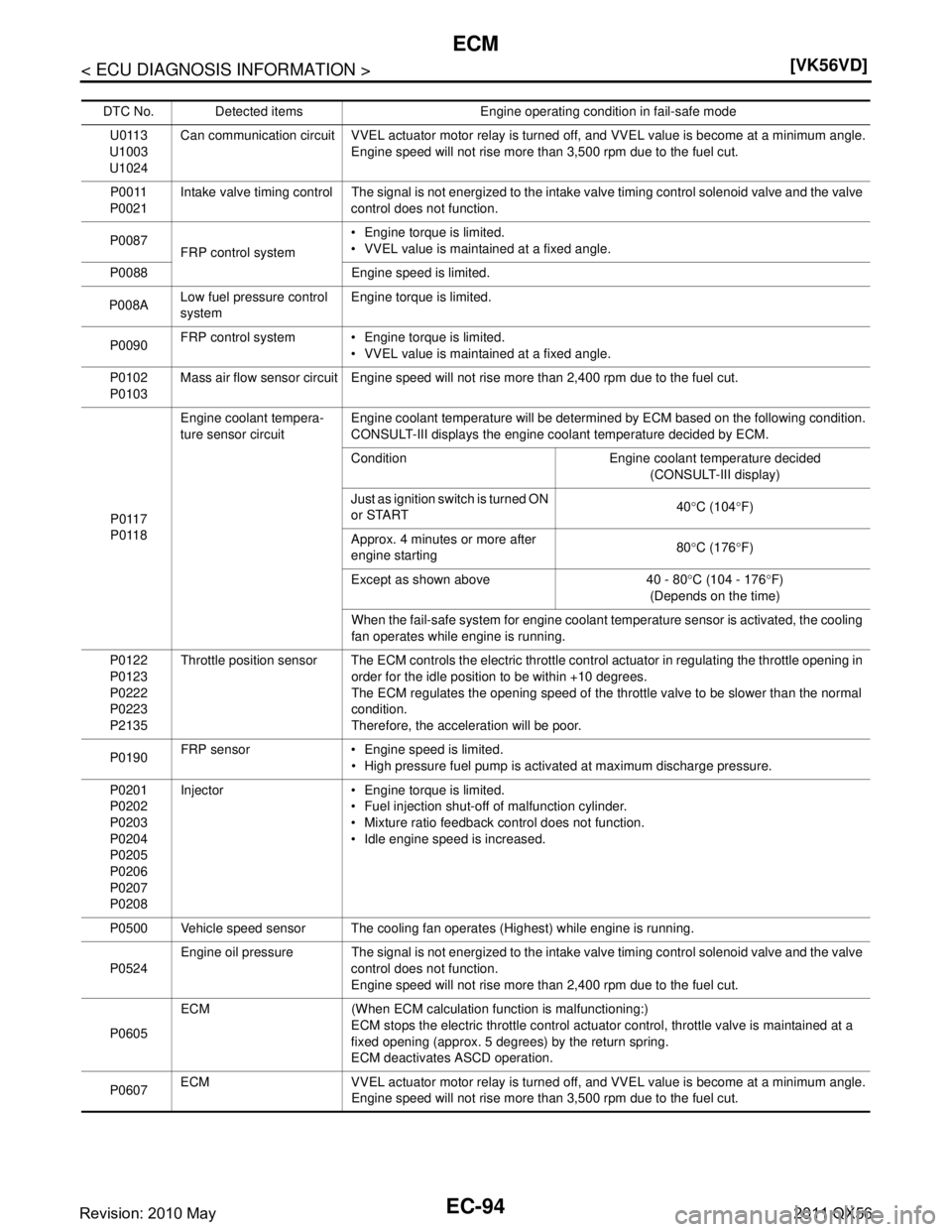
DTC No. Detected items Engine operating condition in fail-safe mode
U0113
U1003
U1024 Can communication circuit VVEL actuator
motor relay is turned off, and VVEL value is become at a minimum angle.
Engine speed will not rise more than 3,500 rpm due to the fuel cut.
P0011
P0021 Intake valve timing control The signal is not energized to the intake valve timing control solenoid valve and the valve
control does not function.
P0087 FRP control system Engine torque is limited.
VVEL value is maintained at a fixed angle.
P0088 Engine speed is limited.
P008A Low fuel pressure control
system Engine torque is limited.
P0090 FRP control system Engine torque is limited.
VVEL value is maintained at a fixed angle.
P0102
P0103 Mass air flow sensor circuit Engine speed will not rise more than 2,400 rpm due to the fuel cut.
P0117
P0118 Engine coolant tempera-
ture sensor circuit
Engine coolant temperature will be determined by ECM based on the following condition.
CONSULT-III displays the engine coolant temperature decided by ECM.
Condition Engine coolant temperature decided
(CONSULT-III display)
Just as ignition switch is turned ON
or START 40
°C (104 °F)
Approx. 4 minutes or more after
engine starting 80
°C (176 °F)
Except as shown above 40 - 80 °C (104 - 176 °F)
(Depends on the time)
When the fail-safe system for engine coolant temperature sensor is activated, the cooling
fan operates while engine is running.
P0122
P0123
P0222
P0223
P2135 Throttle position sensor The ECM controls the electric throttle control actuator in regulating the throttle opening in
order for the idle position to be within +10 degrees.
The ECM regulates the opening speed of the throttle valve to be slower than the normal
condition.
Therefore, the acceleration will be poor.
P0190 FRP sensor Engine speed is limited.
High pressure fuel pump is activated at maximum discharge pressure.
P0201
P0202
P0203
P0204
P0205
P0206
P0207
P0208 Injector Engine torque is limited.
Fuel injection shut-off of malfunction cylinder.
Mixture ratio feedback control does not function.
Idle engine speed is increased.
P0500 Vehicle speed sensor The cooling fan operates (Highest) while engine is running.
P0524 Engine oil pressure The signal is not energized to the intake valve timing control solenoid valve and the valve
control does not function.
Engine speed will not rise more than 2,400 rpm due to the fuel cut.
P0605 ECM (When ECM calculation function is malfunctioning:)
ECM stops the electric throttle control actuator control, throttle valve is maintained at a
fixed opening (approx. 5 degrees) by the return spring.
ECM deactivates ASCD operation.
P0607 ECM VVEL actuator motor relay is
turned off, and VVEL value is become at a minimum angle.
Engine speed will not rise more than 3,500 rpm due to the fuel cut.
Revision: 2010 May2011 QX56