FSU-8
< PERIODIC MAINTENANCE >
WHEEL ALIGNMENT
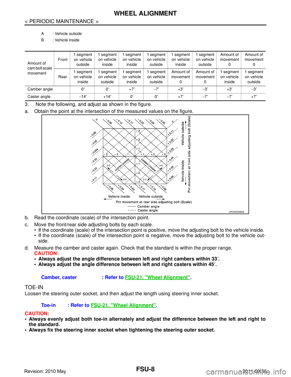
3. Note the following, and adjust as shown in the figure.
a. Obtain the point at the intersection of the measured values on the figure.
b. Read the coordinate (scale) of the intersection point.
c. Move the front/rear side adjusting bolts by each scale. If the coordinate (scale) of the intersection point is positive, move the adjusting bolt to the vehicle inside.
If the coordinate (scale) of the intersection point is negative, move the adjusting bolt to the vehicle out-
side.
d. Measure the camber and caster again. Check that the standard is within the proper range.
CAUTION:
Always adjust the angle difference betw een left and right cambers within 33′.
Always adjust the angle difference be tween left and right casters within 45′.
TOE-IN
Loosen the steering outer socket, and then adjus t the length using steering inner socket.
CAUTION:
Always evenly adjust both toe-in alternately and adjust the difference between the left and right to
the standard.
Always fix the steering inner socket when tightening the steering outer socket.
A : Vehicle outside
B : Vehicle inside
Amount of
cam bolt scale
movement Front
1 segment
on vehicle outside 1 segment
on vehicle inside 1 segment
on vehicle inside 1 segment
on vehicle outside 1 segment
on vehicle inside 1 segment
on vehicle outside Amount of
movement 0 Amount of
movement 0
Rear 1 segment
on vehicle inside 1 segment
on vehicle outside 1 segment
on vehicle inside 1 segment
on vehicle outside Amount of
movement 0 Amount of
movement 0 1 segment
on vehicle inside 1 segment
on vehicle outside
Camber angle 0 ′0′ +7′− 7′ +3′− 3′ +3′− 3′
Caster angle −14 ′ +14′ 0′ 0′ +7′− 7′− 7′ +7′
Camber, caster : Refer to FSU-21, "Wheel Alignment".
JPEIA0239GB
Toe-in : Refer to FSU-21, "Wheel Alignment".
Revision: 2010 May2011 QX56