2011 INFINITI QX56 Open close mirror
[x] Cancel search: Open close mirrorPage 16 of 5598

COMPONENT PARTSADP-7
< SYSTEM DESCRIPTION >
C
DE
F
G H
I
K L
M A
B
ADP
N
O P
Component DescriptionINFOID:0000000006248302
7. ABS actuator and electric unit (con- trol unit)
Refer to BRC-10, "
Component Parts
Location" (With VDC) or BRC-142,
"Component Parts Location" (With
BRAKE ASSIST) or BRC-149,
"Component Parts Location" (With
INTELLIGENT BRAKE ASSIST) 8. Door mirror remote
control switch 9. Seat memory switch
10. Sliding, lifting switch 11. Reclining switch 12. Driver side door switch
13. Door mirror (driver side) 14. T ilt motor 15. Telescopic motor
16. Automatic drive positioner control unit 17. Lifting motor (rear) 18.
Diver seat control unit
19. Lifting motor (front) 20. Sliding motor 21. Reclining motor
A. View with steering column cover low- er removed B. View with instrument lower panel LH
removed C. View with seat cushion pad and seat
back pad removed
D. Backside of seat cushion E. View with seat cushion pad and seat back pad removed
Component parts Description
Driver seat control unit Main units of automatic drive positioner system.
It is connected to the CAN.
It communicates with automatic drive positioner control unit via
UART communication.
It perform memory function after receiving the door unlock signal
from BCM.
The address of each part is recorded.
Operates each motor of seat to the registered position.
Requests the operation of steering column and door mirror to automatic drive positioner control unit
Operates the specific seat motor with the signal from power seat
switch.
Transmits the ignition switch signal (ACC/ON) via UART com- munication to automatic driver positioner control unit.
Automatic drive positioner control unit It communicates with driver seat control unit via UART commu-
nication.
Perform various controls with the instructions of driver seat con- trol unit.
Perform the controls of tilt & telescopic, door mirror and seat memory switch.
Operates steering column and door mirror with the signal from the driver seat control
BCM Recognizes the following status and transmits it to driver seat con-
trol unit via CAN communication.
Handle position: LHD
Driver door: OPEN/CLOSE
Ignition switch position: ACC/ON
Steering lock unit status: LOCK/UNLOCK
Door lock: UNLOCK (with Intelligent key or driver side door re-
quest switch operation)
Key ID
Starter: CRANKING/OTHER
IPDM E/R ON/OFF signal of A/T shift selector (detention switch) is transmit-
ted to driver seat control unit via CAN communication.
TCM The following signals are transmitted to driver seat control unit via
CAN communication.
Shift position signal (P range)
Identification of transmission: A/T
Unified meter and A/C amp. Transmit the vehicle speed signal to driver seat control unit via
CAN communication.
Revision: 2010 May2011 QX56
Page 17 of 5598

ADP-8
< SYSTEM DESCRIPTION >
COMPONENT PARTS
ABS actuator and electric unit (control unit)Transmit the vehicle speed signal to driver seat control unit via
CAN communication.
A/T sift selector (Detention switch) Detention switch is installed on A/T shift selector. It is turned
OFF when A/T shift selector is in P position.
Driver seat control unit judges that A/T shift selector is in P posi- tion if continuity does not exist in this circuit.
Door mirror remote con-
trol switch Mirror switch
Mirror switch is integrated in
door mirror remote control switch.
It operates angle of door mirror face.
It transmits mirror face adjust operation to automatic drive posi- tioner control unit.
Changeover switch Changeover switch is integrated
in door mirror remote control
switch.
Changeover switch has three positions (L, N and R).
It changes operating door mirror motor by transmitting control signal to automatic drive positioner control unit.
Open/close switch Open/close switch is integrated in door mirror remote control
switch.
Power is supplied to folding mi rror from door mirror remote con-
trol switch when operating switch.
Tilt & telescopic switch Tilt switch
Tilt switch is equipped to steering column.
The operation signal is input to automatic drive positioner control
unit when tilt switch is operated.
Telescopic switch Telescopic switch is equipped to steering column.
The operation signal is input to automatic drive positioner control
unit when telescopic switch is operated.
Seat memory switch Set switch
It is used for registration and setting change of driving position and
Intelligent Key interlock function.
Seat memory switch The maximum 2 driving positions can be registered by memory
switch 1 to 2.
Driving position is set to the registered driving position when memory switch is pressed while operation conditions are satis-
fied.
Seat memory indicator Memory indicator indicates the status of auto driving position sys-
tem by turning ON or blinking.
Power seat switch Sliding switch
Sliding switch is equipped to power seat switch on seat cushion
side surface.
The operation signal is input to driver seat control unit when slid- ing switch is operated.
Reclining switch The operation signal is input to driver seat control unit when re-
clining switch is operated.
The operation signal is input to driver seat control unit when re-
clining switch is operated.
Lifting switch (front) Lifting switch (front) is equipped to power seat switch on seat
cushion side surface.
The operation signal is input to driver seat control unit when lift-
ing switch (front) is operated.
Lifting switch (rear) Lifting switch (rear) is equipped to power seat switch on seat
cushion side surface.
The operation signal is input to driver seat control unit when lift-
ing switch (rear) is operated.
Component parts Description
Revision: 2010 May2011 QX56
Page 35 of 5598

ADP-26
< ECU DIAGNOSIS INFORMATION >
DRIVER SEAT CONTROL UNIT
TELESCO SW-FR Telescopic switchForward ON
Other than the above OFF
TELESCO SW-RR Telescopic switch Backward ON
Other than the above OFF
DETENT SW A/T shift selector P position OFF
Other than the above ON
STARTER SW Ignition position Cranking ON
Other than the above OFF
SLIDE PULSE Seat sliding Forward The numeral value decreases *
Backward The numeral value increases*
Other than the above No change to numeral value*
RECLN PULSE Seat reclining Forward The numeral value decreases*
Backward
The numeral value increases
*
Other than the above
No change to numeral value*
LIFT FR PULSE Seat lifter (front) Up
The numeral value decreases
*
Down The numeral value increases *
Other than the above
No change to numeral value*
LIFT RR PULSE Seat lifter (rear) Up
The numeral value decreases
*
Down The numeral value increases *
Other than the above No change to numeral value*
MIR/SEN RH U–D Door mirror (passenger side) Change between 3.4 (close to peak)
0.6 (close to valley)
MIR/SEN RH R–L Door mirror (passenger side) Change between 3.4 (close to left edge)
0.6 (close to right edge)
MIR/SEN LH U–D Door mirror (driver side) Change between 3.4 (close to peak)
0.6 (close to valley)
MIR/SEN LH R–L Door mirror (driver side) Change between 0.6 (close to left edge)
3.4 (close to right edge)
TILT PULSE Tilt position Upward
The numeral value decreases
*
Downward The numeral value increases *
Other than the above
No change to numeral value*
TELESCO PULSE Telescopic position Forward
The numeral value decreases
*
Backward The numeral value increases *
Other than the above
No change to numeral value*
STEERING STATUS Steering lock unit LOCK LOCK
unlock UNLOCK
VEHICLE SPEED The condition of vehicle speed is displayed km/h
P RANG SW CAN A/T shift selector P position ON
Other than the above OFF
R RANGE (CAN) A/T shift selector R position ON
Other than the above OFF
DOOR SW-FL Driver door Open ON
Close OFF
Monitor Item Condition Value/Status
Revision: 2010 May2011 QX56
Page 3041 of 5598
GW-12
< REMOVAL AND INSTALLATION >
WINDSHIELD GLASS
Removal and Installation
INFOID:0000000006220814
REMOVAL
1. Remove front pillar garnish (LH and RH). Refer to INT-14, "Removal and Installation".
2. Remove partially headlining (front edge). Refer to INT-29, "
Removal and Installation".
3. Disconnect inside mirror harness connector.
4. Remove rain sensor cover and then disconnect rain sensor harness connector. Refer to WW-72,
"Removal and Installation".
5. Remove drip molding. Refer to EXT-43, "
Removal and Installation".
6. Remove windshield molding upper using pliers. Refer to GW-11, "
Exploded View".
7. Remove front wiper arm (LH and RH). Refer to WW-66, "
Removal and Installation".
8. Remove cowl top cover. Refer to EXT-21, "
Removal and Installation".
9. Remove front fender cover (LH and RH). Refer to EXT-21, "
Exploded View".
10. Disconnect wiper deicer harness connector (with wiper deicer).
11. Remove front pillar finisher (LH and RH). Refer to EXT-40, "
Removal and Installation".
12. Apply protective tape around the windshield glas s to protect the painted surface from damage.
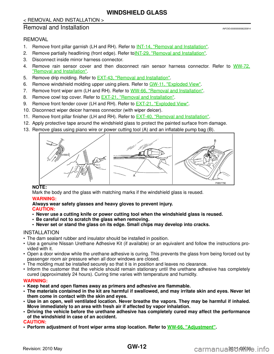
13. Remove glass using piano wire or power cutting tool (A) and an inflatable pump bag (B).
NOTE:
Mark the body and the glass with matching ma rks if the windshield glass is reused.
WARNING:
Always wear safety glasses and heavy gloves to prevent injury.
CAUTION:
Never use a cutting knife or power cutting tool when the windshield glass is reused.
Be careful not to scratch the glass when removing.
Never set or stand the glass on its edge. Small chips may develop into cracks.
INSTALLATION
The dam sealant rubber and insulator should be installed in position.
Use a genuine Nissan Urethane Adhesive Kit (if available) or an equivalent and follow the instructions pro- vided with it.
Open a door window while the urethane adhesive is curing. This prevents the glass from being forced out by
passenger room air pressure when all door windows are closed.
The molding must be installed securely so that it is in position and leaves no clearance.
Inform the customer that the vehicle should rema in stationary until the urethane adhesive has completely
cured (approximately 24 hours). Curing time varies with temperature and humidity.
WARNING:
Keep heat and open flames away as primers and adhesive are flammable.
The materials contained in the ki t are harmful if swallowed, and may irritate skin and eyes. Never let
them come in contact with the skin and eyes.
Use in an open, well ventilated location. Never br eathe the vapors. They may be harmful if inhaled.
Move immediately to an area with fresh air if affected by vapor inhalation.
Driving the vehicle before the urethane adhesive has completely cured may affect the performance
of the windshield in case of an accident.
CAUTION:
Perform adjustment of front wiper arms stop location. Refer to WW-66, "
Adjustment".
PIIB5779E
Revision: 2010 May2011 QX56
Page 3324 of 5598
INTERIOR ROOM LAMP POWER SUPPLY CIRCUIT
INL-57
< DTC/CIRCUIT DIAGNOSIS >
C
D E
F
G H
I
J
K
M A
B
INL
N
O P
YES >> GO TO 2.
NO >> GO TO 3.
2.CHECK INTERIOR ROOM LAMP POWER SUPPLY OPEN CIRCUIT
1. Turn ignition switch OFF.
2. Disconnect the BCM connector.
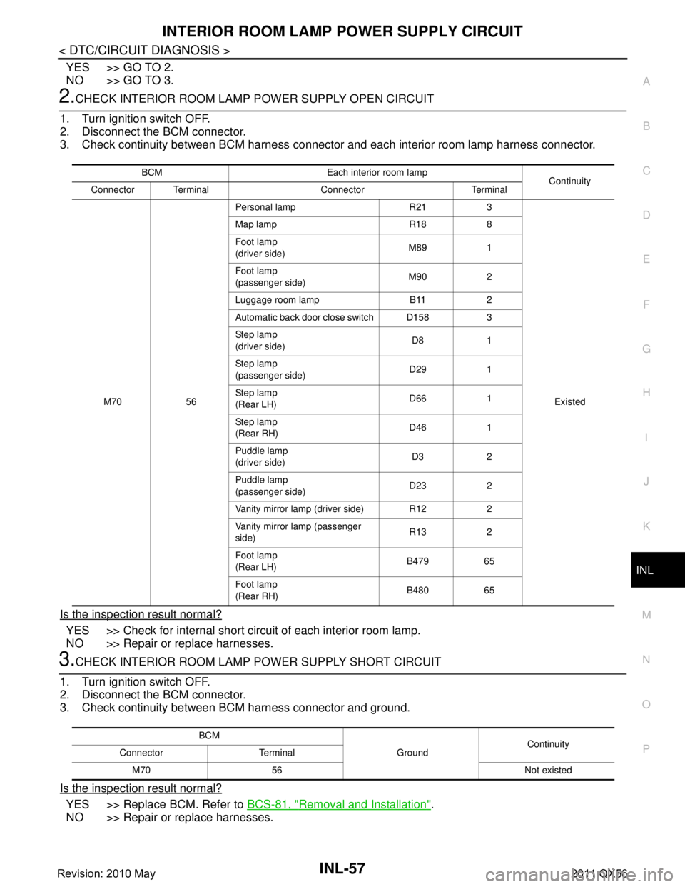
3. Check continuity between BCM harness connector and each interior room lamp harness connector.
Is the inspection result normal?
YES >> Check for internal short circuit of each interior room lamp.
NO >> Repair or replace harnesses.
3.CHECK INTERIOR ROOM LAMP POWER SUPPLY SHORT CIRCUIT
1. Turn ignition switch OFF.
2. Disconnect the BCM connector.
3. Check continuity between BCM harness connector and ground.
Is the inspection result normal?
YES >> Replace BCM. Refer to BCS-81, "Removal and Installation".
NO >> Repair or replace harnesses.
BCM Each interior room lamp Continuity
Connector Terminal Connector Terminal
M70 56 Personal lamp R21 3
Existed
Map lamp R18 8
Foot lamp
(driver side)
M89 1
Foot lamp
(passenger side) M90 2
Luggage room lamp B11 2
Automatic back door close switch D158 3
Ste p l am p
(driver side) D8 1
Ste p l am p
(passenger side) D29 1
Ste p l am p
(Rear LH) D66 1
Ste p l am p
(Rear RH) D46 1
Puddle lamp
(driver side) D3 2
Puddle lamp
(passenger side) D23 2
Vanity mirror lamp (driver side) R12 2
Vanity mirror la mp (passenger
side) R13 2
Foot lamp
(Rear LH) B479 65
Foot lamp
(Rear RH) B480 65
BCM
GroundContinuity
Connector Terminal
M70 56 Not existed
Revision: 2010 May2011 QX56
Page 3334 of 5598
INTERIOR LIGHTING SYSTEM SYMPTOMSINL-67
< SYMPTOM DIAGNOSIS >
C
DE
F
G H
I
J
K
M A
B
INL
N
O P
SYMPTOM DIAGNOSIS
INTERIOR LIGHTING SYSTEM SYMPTOMS
Symptom TableINFOID:0000000006216080
CAUTION:
Perform the self-diagnosis with CONS ULT-III before the symptom diagnosis. Perform the trouble diag-
nosis if any DTC is detected.
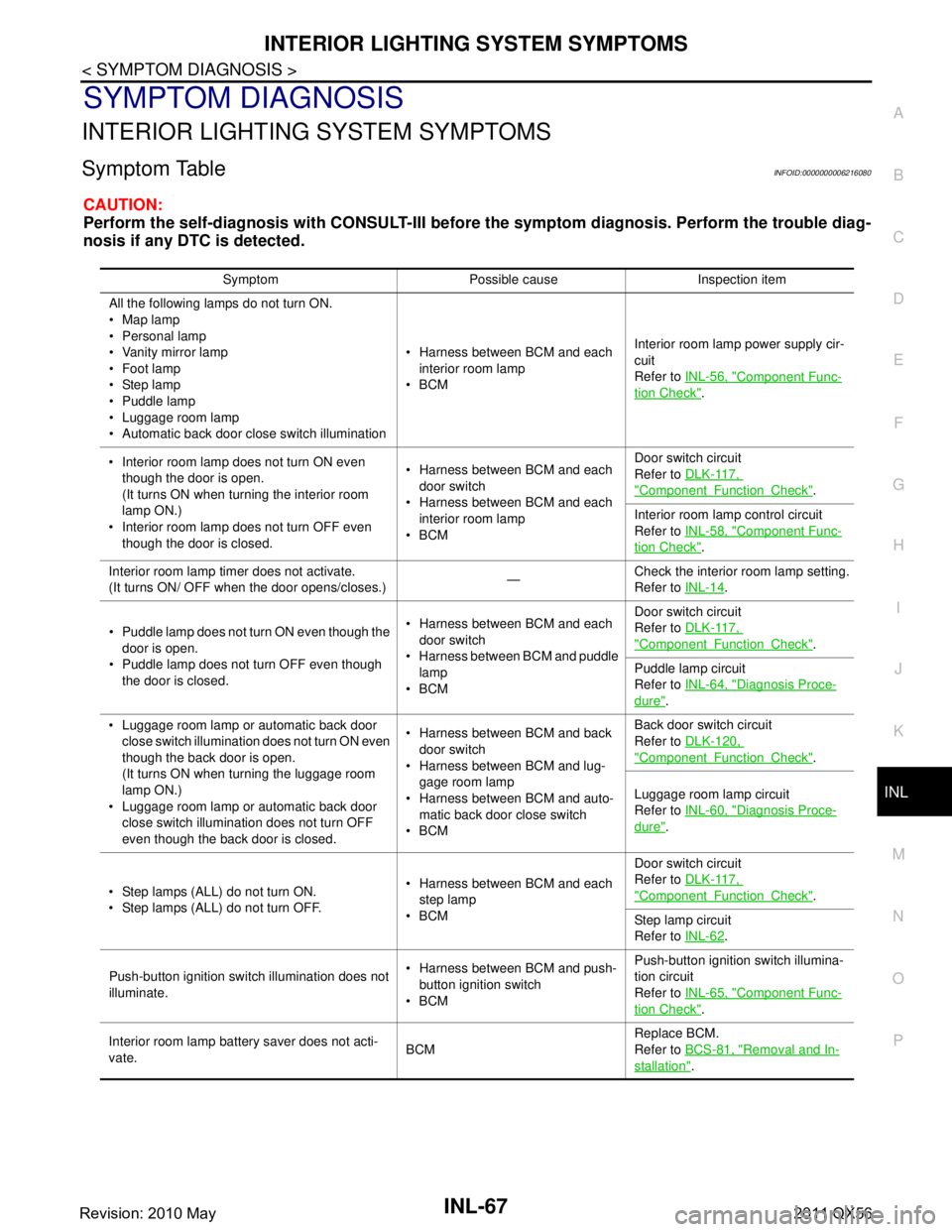
Symptom Possible cause Inspection item
All the following lamps do not turn ON.
Map lamp
Personal lamp
Vanity mirror lamp
Foot lamp
Step lamp
Puddle lamp
Luggage room lamp
Automatic back door close switch illumination Harness between BCM and each
interior room lamp
BCM Interior room lamp
power supply cir-
cuit
Refer to INL-56, "
Component Func-
tion Check".
Interior room lamp does not turn ON even though the door is open.
(It turns ON when turning the interior room
lamp ON.)
Interior room lamp does not turn OFF even
though the door is closed. Harness between BCM and each
door switch
Harness between BCM and each
interior room lamp
BCM Door switch circuit
Refer to
DLK-117,
"ComponentFunctionCheck".
Interior room lamp control circuit
Refer to INL-58, "
Component Func-
tion Check".
Interior room lamp timer does not activate.
(It turns ON/ OFF when the door opens/closes.) —Check the interior room lamp setting.
Refer to
INL-14
.
Puddle lamp does not turn ON even though the door is open.
Puddle lamp does not turn OFF even though the door is closed. Harness between BCM and each
door switch
Harness between BCM and puddle lamp
BCM Door switch circuit
Refer to
DLK-117,
"ComponentFunctionCheck".
Puddle lamp circuit
Refer to INL-64, "
Diagnosis Proce-
dure".
Luggage room lamp or automatic back door close switch illumination does not turn ON even
though the back door is open.
(It turns ON when turning the luggage room
lamp ON.)
Luggage room lamp or automatic back door
close switch illumination does not turn OFF
even though the back door is closed. Harness between BCM and back
door switch
Harness between BCM and lug- gage room lamp
Harness between BCM and auto- matic back door close switch
BCM Back door switch circuit
Refer to
DLK-120,
"ComponentFunctionCheck".
Luggage room lamp circuit
Refer to INL-60, "
Diagnosis Proce-
dure".
Step lamps (ALL) do not turn ON.
Step lamps (ALL) do not turn OFF. Harness between BCM and each
step lamp
BCM Door switch circuit
Refer to
DLK-117,
"ComponentFunctionCheck".
Step lamp circuit
Refer to INL-62
.
Push-button ignition switch illumination does not
illuminate. Harness between BCM and push-
button ignition switch
BCM Push-button ignition switch illumina-
tion circuit
Refer to
INL-65, "
Component Func-
tion Check".
Interior room lamp battery saver does not acti-
vate. BCMReplace BCM.
Refer to
BCS-81, "
Removal and In-
stallation".
Revision: 2010 May2011 QX56
Page 3706 of 5598
MIR-1
DRIVER CONTROLS
C
DE
F
G H
I
J
K
M
SECTION MIR
A
B
MIR
N
O P
CONTENTS
MIRRORS
PRECAUTION ................ ...............................3
PRECAUTIONS .............................................. .....3
Precaution for Supplemental Restraint System
(SRS) "AIR BAG" and "SEAT BELT PRE-TEN-
SIONER" ............................................................. ......
3
Precaution Necessary for Steering Wheel Rota-
tion after Battery Disconnect .....................................
3
PREPARATION ............................................5
PREPARATION .............................................. .....5
Commercial Service Tools ................................. ......5
SYSTEM DESCRIPTION ..............................6
COMPONENT PARTS ................................... .....6
DOOR MIRROR ..................................................... ......6
DOOR MIRROR : Component Parts Location ..........6
DOOR MIRROR : Component Description ...............6
INSIDE MIRROR .................................................... ......7
INSIDE MIRROR : Component Description ..............7
SYSTEM ..............................................................8
DOOR MIRROR SYSTEM ..................................... ......8
DOOR MIRROR SYSTEM : System Diagram ..........8
DOOR MIRROR SYSTEM : System Description ......8
AUTO ANTI-DAZZLING INSIDE MIRROR SYS-
TEM ........................................................................ ......
9
AUTO ANTI-DAZZLING INSIDE MIRROR SYS-
TEM : System Description .........................................
9
ECU DIAGNOSIS INFORMATION ..............10
DRIVER SEAT CONTROL UNIT, AUTOMAT-
IC DRIVE POSITIONER CONTROL UNIT ..... ....
10
List of ECU Reference ........................................ ....10
WIRING DIAGRAM ......................................11
DOOR MIRROR SYSTEM .................................11
Wiring Diagram .................................................... ....11
AUTO ANTI-DAZZLING INSIDE MIRROR
SYSTEM ............................................................
19
Wiring Diagram - INSIDE MIRROR SYSTEM - ... ....19
BASIC INSPECTION ....... ............................21
DIAGNOSIS AND REPAIR WORKFLOW ........21
Work Flow ............................................................ ....21
DTC/CIRCUIT DIAGNOSIS .........................22
DOOR MIRROR REMOTE CONTROL
SWITCH .............................................................
22
OPEN/CLOSE SWITCH ......................................... ....22
OPEN/CLOSE SWITCH : Component Inspection ....22
SYMPTOM DIAGNOSIS ..............................23
REVERSE INTERLOCK DOOR MIRROR
DOES NOT OPERATE ......................................
23
Diagnosis Procedure ........................................... ....23
SQUEAK AND RATTLE TROUBLE DIAG-
NOSES ..............................................................
24
Work Flow ................................................................24
Inspection Procedure ...............................................26
Diagnostic Worksheet ..............................................28
REMOVAL AND INSTALLATION ...............30
INSIDE MIRROR ...............................................30
Exploded View ..................................................... ....30
Removal and Installation .........................................30
OUTSIDE MIRROR ...........................................32
Exploded View .........................................................32
DOOR MIRROR ASSEMBLY ....................................32
Revision: 2010 May2011 QX56
Page 3711 of 5598
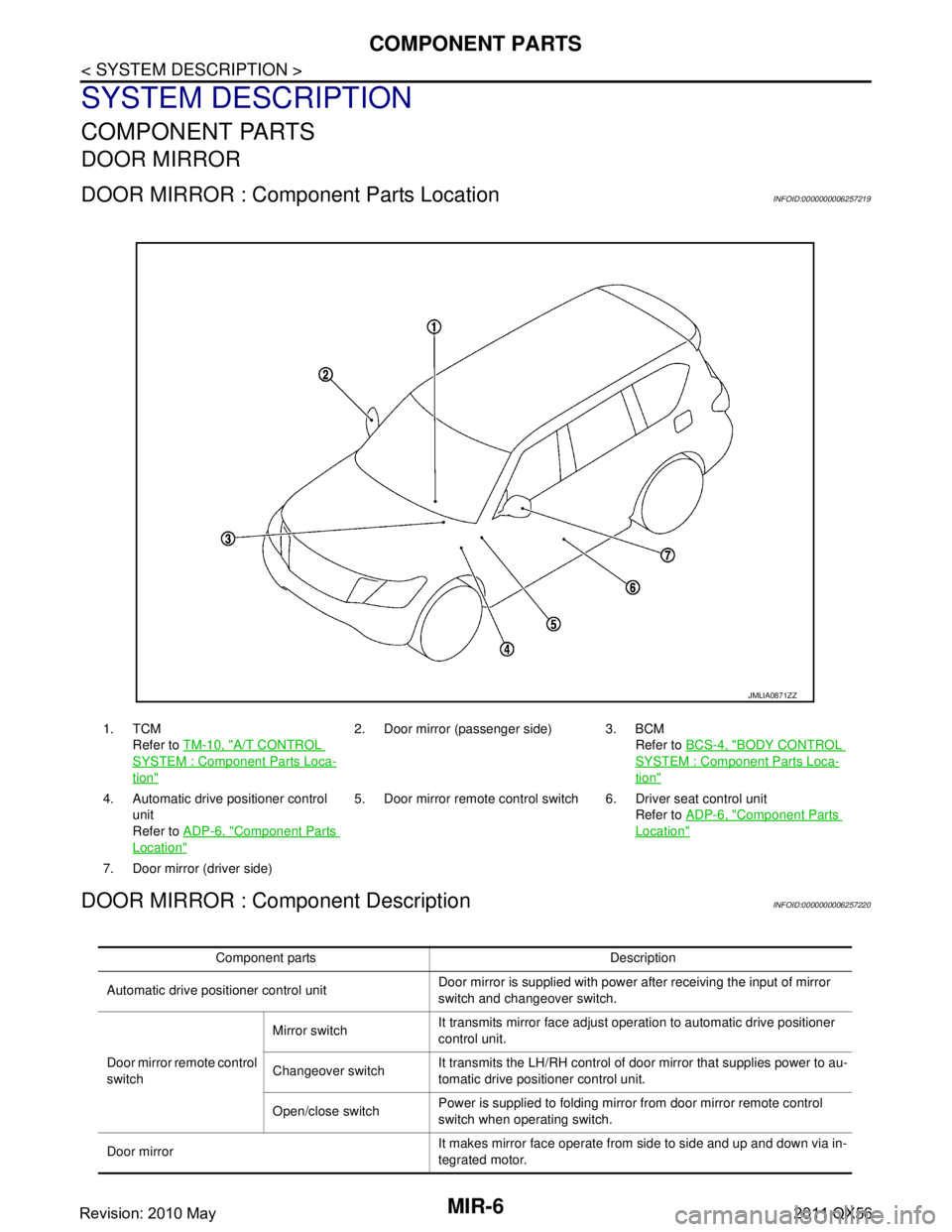
MIR-6
< SYSTEM DESCRIPTION >
COMPONENT PARTS
SYSTEM DESCRIPTION
COMPONENT PARTS
DOOR MIRROR
DOOR MIRROR : Component Parts LocationINFOID:0000000006257219
DOOR MIRROR : Component DescriptionINFOID:0000000006257220
1. TCMRefer to TM-10, "
A/T CONTROL
SYSTEM : Componen t Parts Loca-
tion"
2. Door mirror (passenger side) 3. BCM
Refer to BCS-4, "
BODY CONTROL
SYSTEM : Component Parts Loca-
tion"
4. Automatic drive positioner control
unit
Refer to ADP-6, "
Component Parts
Location"
5. Door mirror remote control switch 6. Driver seat control unit
Refer to ADP-6, "
Component Parts
Location"
7. Door mirror (driver side)
JMLIA0871ZZ
Component parts Description
Automatic drive positioner control unit Door mirror is supplied with power after receiving the input of mirror
switch and changeover switch.
Door mirror re mote control
switch Mirror switch
It transmits mirror face adjust operation to automatic drive positioner
control unit.
Changeover switch It transmits the LH/RH control of door mirror that supplies power to au-
tomatic drive positioner control unit.
Open/close switch Power is supplied to folding mirro
r from door mirror remote control
switch when operating switch.
Door mirror It makes mirror face operate from side to side and up and down via in-
tegrated motor.
Revision: 2010 May2011 QX56