2011 INFINITI QX56 FSU-1
[x] Cancel search: FSU-1Page 2909 of 5598
![INFINITI QX56 2011 Factory Service Manual
FRONT WHEEL HUB AND KNUCKLEFAX-9
< REMOVAL AND INSTALLATION > [2WD]
C
EF
G H
I
J
K L
M A
B
FA X
N
O P
8. Remove shock absorber mounting bolt from lower link. Refer to FSU-10, "Removal and Installati](/manual-img/42/57033/w960_57033-2908.png "INFINITI QX56 2011 Factory Service Manual
FRONT WHEEL HUB AND KNUCKLEFAX-9
< REMOVAL AND INSTALLATION > [2WD]
C
EF
G H
I
J
K L
M A
B
FA X
N
O P
8. Remove shock absorber mounting bolt from lower link. Refer to FSU-10, \"Removal and Installati")
FRONT WHEEL HUB AND KNUCKLEFAX-9
< REMOVAL AND INSTALLATION > [2WD]
C
EF
G H
I
J
K L
M A
B
FA X
N
O P
8. Remove shock absorber mounting bolt from lower link. Refer to FSU-10, "Removal and Installation".
9. Separate upper link from steering knuckle, using the ball joint remover (commercial service tool), and
remove upper link.
CAUTION:
Temporarily tighten the nut to prevent damage to threads and to prevent the ball joint remover
from suddenly coming off.
Never damage ball joint boot.
10. Remove wheel hub and bearing assembly, and then remove splash guard.
11. Remove lower link from steering knuckle. CAUTION:
Never damage ball joint boot.
12. Remove steering knuckle.
13. Remove hub bolts (1) from wheel hub and bearing assembly, using the ball joint remover (A) (commercial service tool).
CAUTION:
Remove hub bolt only when necessary.
Never hammer the hub bolt to avoid impact to the wheel
hub and bearing assembly.
Pull out the hub bolt in a di rection perpendicular to the
wheel hub and bearing assembly.
14. Perform inspection after removal. Refer to FAX-9, "
Inspection".
INSTALLATION
Note the following, and install in the reverse order of removal.
Place a suitable washer (A) as shown in the figure to install the hub
bolts (1) by using the tightening force of the nut (B).
CAUTION:
Check that there is no cl earance between wheel hub and
bearing assembly, and hub bolt.
Never reuse hub bolt.
Perform the final tightening of each of parts under unladen condi-
tions, which were removed when removing wheel hub and bearing
assembly and steering knuckle.
Never reuse cotter pin.
Perform inspection after installation. Refer to FA X - 9 , "
Inspection".
InspectionINFOID:0000000006225420
INSPECTION AFTER REMOVAL
Check components for deformation, cracks, and other damage. Replace it if necessary.
Ball Joint Inspection
Check boots of lower link and steering outer socket ba ll joint for breakage, axial play, and torque. Refer to
FSU-15, "
Inspection" and ST-46, "Inspection".
INSPECTION AFTER INSTALLATION
1. Check wheel sensor harness for proper connection. Refer to BRC-134, "FRONT WHEEL SENSOR :
Exploded View".
2. Check the wheel alignment. Refer to FSU-7, "
Inspection".
3. Adjust neutral position of steering angle sensor. Refer to BRC-64, "
Work Procedure".
JPDIF0299ZZ
JPDIF0300ZZ
Revision: 2010 May2011 QX56
Page 2919 of 5598
![INFINITI QX56 2011 Factory Service Manual
FRONT WHEEL HUB AND KNUCKLEFAX-19
< REMOVAL AND INSTALLATION > [4WD]
C
EF
G H
I
J
K L
M A
B
FA X
N
O P
7. Set suitable jack under lower link.
8. Remove shock absorber mounting bolt from lower link. R](/manual-img/42/57033/w960_57033-2918.png "INFINITI QX56 2011 Factory Service Manual
FRONT WHEEL HUB AND KNUCKLEFAX-19
< REMOVAL AND INSTALLATION > [4WD]
C
EF
G H
I
J
K L
M A
B
FA X
N
O P
7. Set suitable jack under lower link.
8. Remove shock absorber mounting bolt from lower link. R")
FRONT WHEEL HUB AND KNUCKLEFAX-19
< REMOVAL AND INSTALLATION > [4WD]
C
EF
G H
I
J
K L
M A
B
FA X
N
O P
7. Set suitable jack under lower link.
8. Remove shock absorber mounting bolt from lower link. Refer to FSU-10, "
Removal and Installation".
9. Separate upper link from steering knuckle, using the ball joint remover (commercial service tool), and
remove upper link.
CAUTION:
Temporarily tighten the nut to prevent damage to threads and to prevent the ball joint remover
from suddenly coming off.
Never damage ball joint boot.
10. Remove cotter pin, and then loosen wheel hub lock nut.
11. Put matching mark on drive shaft and wheel hub and bearing assembly. CAUTION:
Use paint or similar substance for matc hing marks. Never scratch the surface.
12. Patch wheel hub lock nut with a piece of wood. Hammer the wood to disengage wheel hub and bearing assembly from drive shaft.
CAUTION:
Never place drive shaft joint at an extreme angle. Also be careful not to overextend slide joint.
Never allow drive shaft to hang down without support for or joint sub-assembly, shaft and the
other parts.
NOTE:
Use suitable puller, if wheel hub and bearing assembly and drive shaft cannot be separated even after
performing the above procedure.
13. Remove wheel hub lock nut.
14. Remove wheel hub and bearing assembly, and then remove splash guard.
15. Remove lower link from steering knuckle. CAUTION:
Never damage ball joint boot.
16. Remove steering knuckle.
17. Remove hub bolts (1) from wheel hub and bearing assembly, using the ball joint remover (A) (commercial service tool).
CAUTION:
Remove hub bolt only when necessary.
Never hammer the hub bolt to avoid impact to the wheel
hub and bearing assembly.
Pull out the hub bolt in a di rection perpendicular to the
wheel hub and bearing assembly.
18. Perform inspection after removal. Refer to FAX-20, "
Inspection".
INSTALLATION
Note the following, and install in the reverse order of removal.
Place a suitable washer (A) as shown in the figure to install the hub
bolts (1) by using the tightening force of the nut (B).
CAUTION:
Check that there is no cl earance between wheel hub and
bearing assembly, and hub bolt.
Never reuse hub bolt.
Use the following torque range for tightening the wheel hub lock nut.
CAUTION:
Since the drive shaft is assembled by press-fitting , use the tightening torque range for the wheel
hub lock nut.
Be sure to use torque wrench to tighten th e wheel hub lock nut. Never use a power tool.
Perform the final tightening of each of parts under unladen conditions, which were removed when removing
wheel hub and bearing assembly and steering knuckle.
JPDIF0299ZZ
: 118 – 123 N·m (12.1 – 12.5 kg-m, 87 – 90 ft-lb)
JPDIF0300ZZ
Revision: 2010 May2011 QX56
Page 2920 of 5598
![INFINITI QX56 2011 Factory Service Manual
FAX-20
< REMOVAL AND INSTALLATION >[4WD]
FRONT WHEEL HUB AND KNUCKLE
Never reuse cotter pin.
Perform inspection after installation. Refer to
FAX-20, "
Inspection".
InspectionINFOID:0000000006225](/manual-img/42/57033/w960_57033-2919.png "INFINITI QX56 2011 Factory Service Manual
FAX-20
< REMOVAL AND INSTALLATION >[4WD]
FRONT WHEEL HUB AND KNUCKLE
Never reuse cotter pin.
Perform inspection after installation. Refer to
FAX-20, \"
Inspection\".
InspectionINFOID:0000000006225")
FAX-20
< REMOVAL AND INSTALLATION >[4WD]
FRONT WHEEL HUB AND KNUCKLE
Never reuse cotter pin.
Perform inspection after installation. Refer to
FAX-20, "
Inspection".
InspectionINFOID:0000000006225398
INSPECTION AFTER REMOVAL
Check components for deformation, cracks, and other damage. Replace it if necessary.
Ball Joint Inspection
Check boots of lower link and steering outer socket ball joint for breakage, axial play, and torque. Refer to
FSU-15, "
Inspection" and ST-46, "Inspection".
INSPECTION AFTER INSTALLATION
1. Check wheel sensor harness for proper connection. Refer to BRC-134, "FRONT WHEEL SENSOR :
Exploded View".
2. Check the wheel alignment. Refer to FSU-7, "
Inspection".
3. Adjust neutral position of steering angle sensor. Refer to BRC-64, "
Work Procedure".
Revision: 2010 May2011 QX56
Page 2922 of 5598
![INFINITI QX56 2011 Factory Service Manual
FAX-22
< REMOVAL AND INSTALLATION >[4WD]
FRONT DRIVE SHAFT
FRONT DRIVE SHAFT
Exploded ViewINFOID:0000000006225402
Removal and InstallationINFOID:0000000006225403
REMOVAL
1. Remove tires.
2. Remove br](/manual-img/42/57033/w960_57033-2921.png "INFINITI QX56 2011 Factory Service Manual
FAX-22
< REMOVAL AND INSTALLATION >[4WD]
FRONT DRIVE SHAFT
FRONT DRIVE SHAFT
Exploded ViewINFOID:0000000006225402
Removal and InstallationINFOID:0000000006225403
REMOVAL
1. Remove tires.
2. Remove br")
FAX-22
< REMOVAL AND INSTALLATION >[4WD]
FRONT DRIVE SHAFT
FRONT DRIVE SHAFT
Exploded ViewINFOID:0000000006225402
Removal and InstallationINFOID:0000000006225403
REMOVAL
1. Remove tires.
2. Remove brake hose bracket. Refer to
BR-23, "
FRONT : Removal and Installation".
3. Remove caliper assembly mounting bolts. Hang caliper assembly in a place where it will not interfere with work. Refer to BR-37, "
BRAKE CALIPER ASSEMBLY : Removal and Installation".
CAUTION:
Never depress brake pedal while brake caliper is removed.
4. Remove disc rotor. Refer to FAX-18, "
Removal and Installation".
5. Remove wheel sensor harness. Refer to BRC-134, "
FRONT WHEEL SENSOR : Removal and Installa-
tion".
CAUTION:
Never pull on wheel sensor harness.
6. Remove height sensor from upper link (right side). Refer to EXL-136, "
Removal and Installation".
7. Remove steering outer socket. Refer to ST-42, "
Removal and Installation".
8. Set suitable jack under lower link.
9. Remove shock absorber mounting bolt from lower link. Refer to FSU-10, "
Removal and Installation".
10. Separate upper link from steering knuckle, using t he ball joint remover (commercial service tool), and
remove upper link.
CAUTION:
Temporarily tighten the nut to prevent damage to threads and to prevent the ball joint remover
from suddenly coming off.
1. Circular clip 2. Dust shield 3. Housing
4. Snap ring 5. Ball cage/steel ball/inner race assem-
bly6. Stopper ring
7. Boot band 8. Boot 9. Shaft
10. Circular clip 11. Joint sub-assembly : Wheel side
: NISSAN genuine grease or an equivalent.
Refer to GI-4, "
Components" for symbols not described on the above.
JPDIF0279ZZ
Revision: 2010 May2011 QX56
Page 2943 of 5598

FSU-1
SUSPENSION
C
DF
G H
I
J
K L
M
SECTION FSU
A
B
FSU
N
O PCONTENTS
FRONT SUSPENSION
PRECAUTION ................ ...............................2
PRECAUTIONS .............................................. .....2
Precaution for Supplemental Restraint System
(SRS) "AIR BAG" and "SEAT BELT PRE-TEN-
SIONER" ............................................................. ......
2
Precaution Necessary for Steering Wheel Rota-
tion after Battery Disconnect .....................................
2
Precaution for Procedure without Cowl Top Cover ......3
Precautions for Suspension ......................................3
PREPARATION ............................................4
PREPARATION .............................................. .....4
Special Service Tools .......................................... ......4
Commercial Service Tools ........................................4
SYMPTOM DIAGNOSIS ...............................5
NOISE, VIBRATION AND HARSHNESS
(NVH) TROUBLESHOOTING ........................ .....
5
NVH Troubleshooting Chart ................................ ......5
PERIODIC MAINTENANCE ..........................6
FRONT SUSPENSION ASSEMBLY .............. .....6
Inspection ............................................................ ......6
WHEEL ALIGNMENT ..........................................7
Inspection ............................................................ ......7
Adjustment ................................................................7
REMOVAL AND INSTALLATION ................9
FRONT COIL SPRING AND SHOCK AB-
SORBER ............................................................
9
Exploded View ..................................................... .....9
Removal and Installation .........................................10
Disassembly and Assembly .....................................11
Inspection and Adjustment ......................................12
Disposal ...................................................................13
LOWER LINK ....................................................14
Exploded View .........................................................14
Removal and Installation .........................................14
Inspection ................................................................15
UPPER LINK ......................... ............................17
Exploded View ..................................................... ....17
Removal and Installation .........................................17
Inspection ................................................................18
FRONT STABILIZER ........................................20
Exploded View .........................................................20
Removal and Installation .........................................20
Inspection ................................................................20
SERVICE DATA AND SPECIFICATIONS
(SDS) ............... .............................................
21
SERVICE DATA AND SPECIFICATIONS
(SDS) .................................................................
21
Wheel Alignment ................................................. ....21
Ball Joint ..................................................................21
Wheel Height ...........................................................21
Revision: 2010 May2011 QX56
Page 2947 of 5598
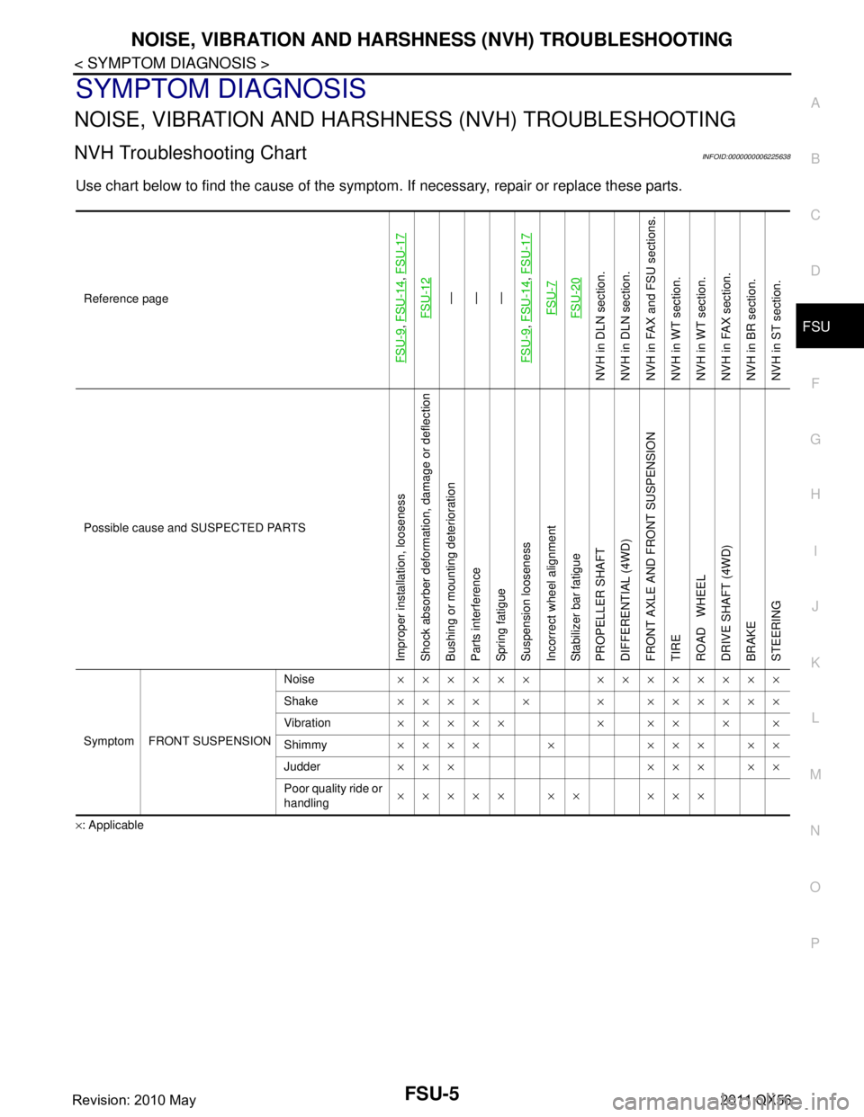
NOISE, VIBRATION AND HARSHNESS (NVH) TROUBLESHOOTINGFSU-5
< SYMPTOM DIAGNOSIS >
C
DF
G H
I
J
K L
M A
B
FSU
N
O P
SYMPTOM DIAGNOSIS
NOISE, VIBRATION AND HARSHN ESS (NVH) TROUBLESHOOTING
NVH Troubleshooting ChartINFOID:0000000006225638
Use chart below to find the cause of the symptom. If necessary, repair or replace these parts.
×: ApplicableReference page
FSU-9
,
FSU-14
, FSU-17
FSU-12
—
—
—
FSU-9
, FSU-14
, FSU-17
FSU-7FSU-20
NVH in DLN section.
NVH in DLN section.
NVH in FAX and FSU sections.
NVH in WT section.
NVH in WT section.
NVH in FAX section.
NVH in BR section.
NVH in ST section.
Possible cause and SUSPECTED PARTS
Improper installation, looseness
Shock absorber deformation, damage or deflection
Bushing or mounting deterioration
Parts interference
Spring fatigue
Suspension looseness
Incorrect wheel alignment
Stabilizer bar fatigue
PROPELLER SHAFT
DIFFERENTIAL (4WD)
FRONT AXLE AND FRONT SUSPENSION
TIRE
ROAD WHEEL
DRIVE SHAFT (4WD)
BRAKE
STEERING
Symptom FRONT SUSPENSION Noise
×××××× ××××××××
Shake ×××× × × ××××××
Vibration ××××× × ×× × ×
Shimmy ×××× × ××× ××
Judder ××× ××× ××
Poor quality ride or
handling ××××× ×× ×××
Revision: 2010 May2011 QX56
Page 2949 of 5598
WHEEL ALIGNMENTFSU-7
< PERIODIC MAINTENANCE >
C
DF
G H
I
J
K L
M A
B
FSU
N
O P
WHEEL ALIGNMENT
InspectionINFOID:0000000006225640
DESCRIPTION
Measure wheel alignment under unladen conditions.
NOTE:
“Unladen conditions” means that fuel, engine coolant, and lubricant are full. Spare tire, jack, hand tools and
mats are in designated positions.
PRELIMINARY CHECK
Check the following:
Tires for improper air pressure and wear
Road wheels for runout: Refer to WT-64, "
Inspection".
Wheel bearing axial end play: Refer to FA X - 7 , "
Inspection" (2WD), FAX-16, "Inspection" (4WD).
Lower link and upper link ball joint axial end play: Refer to FSU-15, "
Inspection" and FSU-18, "Inspection".
Shock absorber operation.
Each mounting part of axle and suspension for looseness and deformation
Lower link for cracks, deformation and other damage
Vehicle height (posture)
GENERAL INFORMATION AND RECOMMENDATIONS
A four-wheel thrust alignment should be performed.
- This type of alignment is recomm ended for any NISSAN/INFINITI vehicle.
- The four-wheel “thrust” process helps ensure that t he vehicle is properly aligned and the steering wheel is
centered.
- The alignment rack itself should be capable of accepting any NISSAN/INFINITI vehicle.
- The rack should be checked to ensure that it is level.
Make sure the machine is properly calibrated.
- Your alignment equipment should be regularly ca librated in order to give correct information.
- Check with the manufacturer of your specific equi pment for their recommended Service/Calibration Sched-
ule.
ALIGNMENT PROCESS
IMPORTANT:
Use only the alignment specificati ons listed in this Service Manual.
When displaying the alignment settings, many alignment machines use “indicators”: (Green/red, plus or
minus, Go/No Go). Never use these indicators.
- The alignment specifications programmed into your machine that operate these indicators may not be cor-
rect.
- This may result in an ERROR.
Some newer alignment machines are equipped with an optional “Rolling Compensation” method to “com-
pensate” the sensors (alignment targets or head units). Never use this “Rolling Compensation” method.
- Use the “Jacking Compensation Method”. After installi ng the alignment targets or head units, raise the vehi-
cle and rotate the wheels 1/2 turn both ways.
- See Instructions in the alignment machine you're using for more information on this.
AdjustmentINFOID:0000000006225641
CAMBER, CASTER
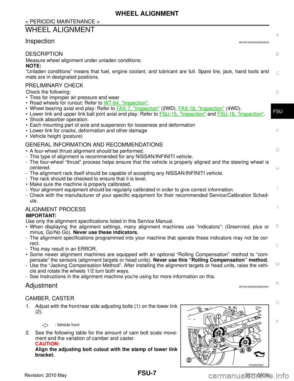
1. Adjust with the front/rear side adjusting bolts (1) on the lower link
(2).
2. See the following table for the amount of cam bolt scale move- ment and the variation of camber and caster.
CAUTION:
Align the adjusting bolt cutout with the stamp of lower link
bracket.
: Vehicle front
JPEIA0235ZZ
Revision: 2010 May2011 QX56
Page 2952 of 5598
FSU-10
< REMOVAL AND INSTALLATION >
FRONT COIL SPRING AND SHOCK ABSORBER
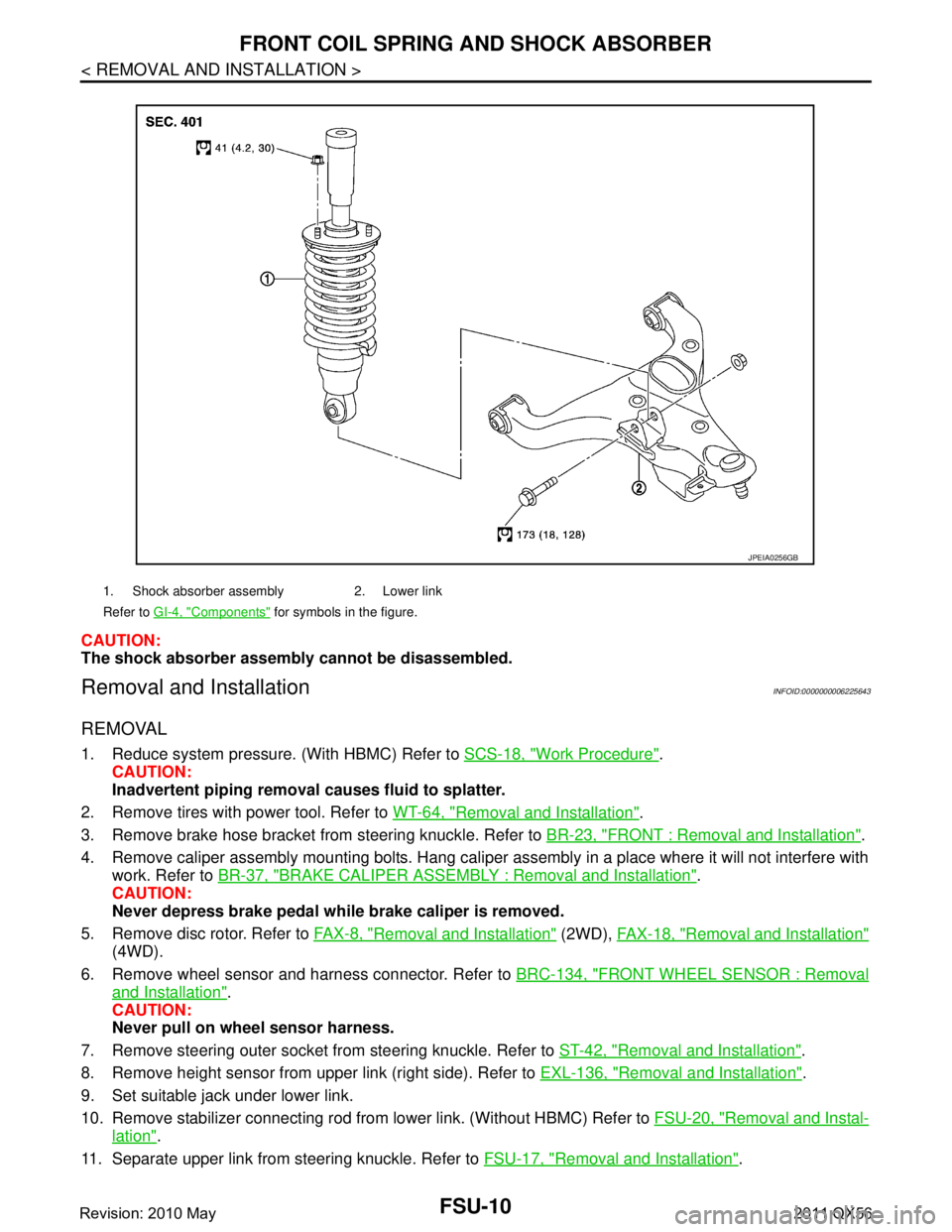
CAUTION:
The shock absorber assembly cannot be disassembled.
Removal and InstallationINFOID:0000000006225643
REMOVAL
1. Reduce system pressure. (With HBMC) Refer to SCS-18, "Work Procedure".
CAUTION:
Inadvertent piping removal causes fluid to splatter.
2. Remove tires with power tool. Refer to WT-64, "
Removal and Installation".
3. Remove brake hose bracket from steering knuckle. Refer to BR-23, "
FRONT : Removal and Installation".
4. Remove caliper assembly mounting bolts. Hang caliper assembly in a place where it will not interfere with work. Refer to BR-37, "
BRAKE CALIPER ASSEMBLY : Removal and Installation".
CAUTION:
Never depress brake pedal while brake caliper is removed.
5. Remove disc rotor. Refer to FA X - 8 , "
Removal and Installation" (2WD), FAX-18, "Removal and Installation"
(4WD).
6. Remove wheel sensor and harness connector. Refer to BRC-134, "
FRONT WHEEL SENSOR : Removal
and Installation".
CAUTION:
Never pull on wheel sensor harness.
7. Remove steering outer socket fr om steering knuckle. Refer to ST-42, "
Removal and Installation".
8. Remove height sensor from upper link (right side). Refer to EXL-136, "
Removal and Installation".
9. Set suitable jack under lower link.
10. Remove stabilizer connecting rod from lower link. (Without HBMC) Refer to FSU-20, "
Removal and Instal-
lation".
11. Separate upper link from steering knuckle. Refer to FSU-17, "
Removal and Installation".
1. Shock absorber assembly 2. Lower link
Refer to GI-4, "
Components" for symbols in the figure.
JPEIA0256GB
Revision: 2010 May2011 QX56