2011 INFINITI QX56 fuel pump
[x] Cancel search: fuel pumpPage 2223 of 5598
P008A LOW FUEL PRESSURE CONTROL SYSTEMEC-199
< DTC/CIRCUIT DIAGNOSIS > [VK56VD]
C
D
E
F
G H
I
J
K L
M A
EC
NP
O
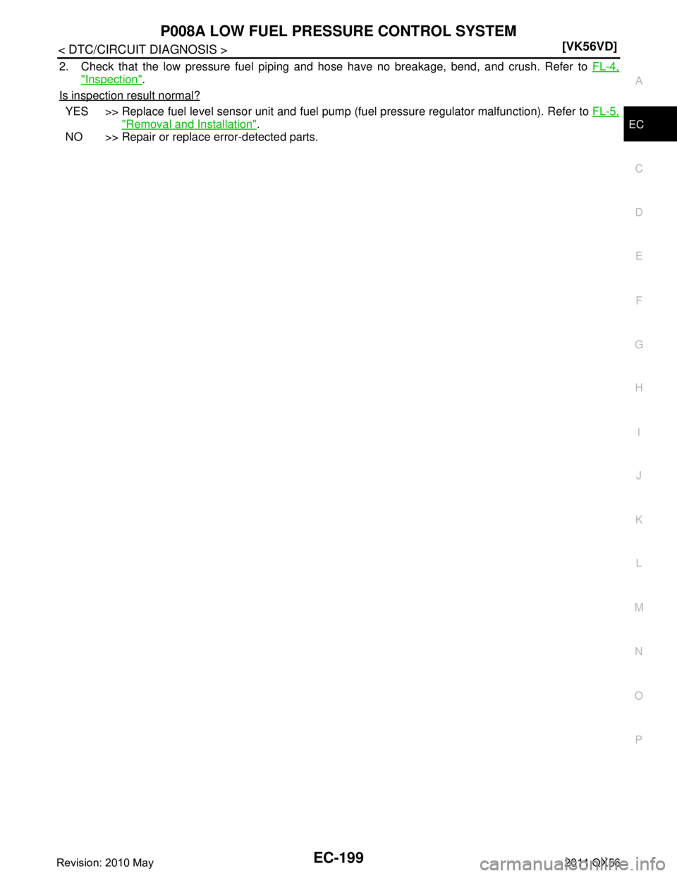
2. Check that the low pressure fuel piping and hose have no breakage, bend, and crush. Refer to
FL-4,
"Inspection".
Is inspection result normal?
YES >> Replace fuel level sensor unit and fuel pump (fuel pressure regulator malfunction). Refer to FL-5,
"Removal and Installation".
NO >> Repair or replace error-detected parts.
Revision: 2010 May2011 QX56
Page 2224 of 5598
EC-200
< DTC/CIRCUIT DIAGNOSIS >[VK56VD]
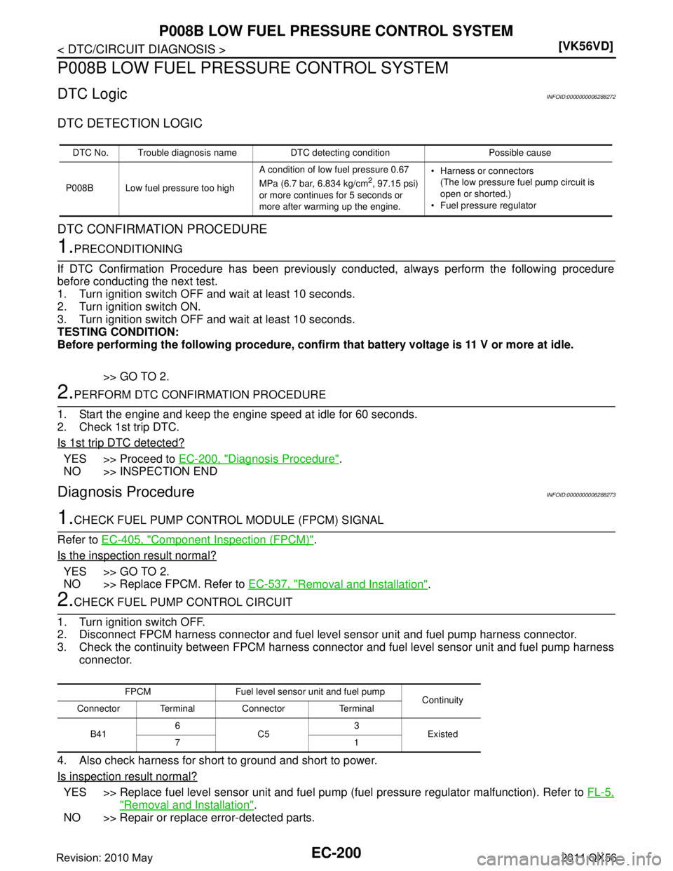
P008B LOW FUEL PRESSURE CONTROL SYSTEM
P008B LOW FUEL PRESSURE CONTROL SYSTEM
DTC LogicINFOID:0000000006288272
DTC DETECTION LOGIC
DTC CONFIRMATION PROCEDURE
1.PRECONDITIONING
If DTC Confirmation Procedure has been previously conducted, always perform the following procedure
before conducting the next test.
1. Turn ignition switch OFF and wait at least 10 seconds.
2. Turn ignition switch ON.
3. Turn ignition switch OFF and wait at least 10 seconds.
TESTING CONDITION:
Before performing the following procedure, confirm that battery voltage is 11 V or more at idle.
>> GO TO 2.
2.PERFORM DTC CONFIRMATION PROCEDURE
1. Start the engine and keep the engine speed at idle for 60 seconds.
2. Check 1st trip DTC.
Is 1st trip DTC detected?
YES >> Proceed to EC-200, "Diagnosis Procedure".
NO >> INSPECTION END
Diagnosis ProcedureINFOID:0000000006288273
1.CHECK FUEL PUMP CONTROL MODULE (FPCM) SIGNAL
Refer to EC-405, "
Component Inspection (FPCM)".
Is the inspection result normal?
YES >> GO TO 2.
NO >> Replace FPCM. Refer to EC-537, "
Removal and Installation".
2.CHECK FUEL PUMP CONTROL CIRCUIT
1. Turn ignition switch OFF.
2. Disconnect FPCM harness connector and fuel level sensor unit and fuel pump harness connector.
3. Check the continuity between FPCM harness connecto r and fuel level sensor unit and fuel pump harness
connector.
4. Also check harness for short to ground and short to power.
Is inspection result normal?
YES >> Replace fuel level sensor unit and fuel pump (fuel pressure regulator malfunction). Refer to FL-5,
"Removal and Installation".
NO >> Repair or replace error-detected parts.
DTC No. Trouble diagnosis name DTC detecting condition Possible cause
P008B Low fuel pressure too high A condition of low fuel pressure 0.67
MPa (6.7 bar, 6.834 kg/cm
2, 97.15 psi)
or more continues for 5 seconds or
more after warming up the engine. Harness or connectors
(The low pressure fuel pump circuit is
open or shorted.)
Fuel pressure regulator
FPCM Fuel level sensor unit and fuel pump Continuity
Connector Terminal Connector Terminal
B41 6
C5 3
Existed
71
Revision: 2010 May2011 QX56
Page 2239 of 5598
P0116 ECT SENSOREC-215
< DTC/CIRCUIT DIAGNOSIS > [VK56VD]
C
D
E
F
G H
I
J
K L
M A
EC
NP
O
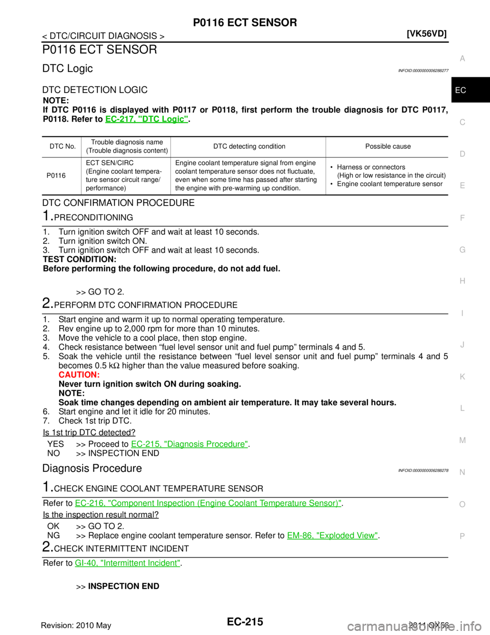
P0116 ECT SENSOR
DTC LogicINFOID:0000000006288277
DTC DETECTION LOGIC
NOTE:
If DTC P0116 is displayed with P0117 or P0118,
first perform the trouble diagnosis for DTC P0117,
P0118. Refer to EC-217, "
DTC Logic".
DTC CONFIRMATION PROCEDURE
1.PRECONDITIONING
1. Turn ignition switch OFF and wait at least 10 seconds.
2. Turn ignition switch ON.
3. Turn ignition switch OFF and wait at least 10 seconds.
TEST CONDITION:
Before performing the following procedure, do not add fuel.
>> GO TO 2.
2.PERFORM DTC CONFIRMATION PROCEDURE
1. Start engine and warm it up to normal operating temperature.
2. Rev engine up to 2,000 rpm for more than 10 minutes.
3. Move the vehicle to a cool place, then stop engine.
4. Check resistance between “fuel level s ensor unit and fuel pump” terminals 4 and 5.
5. Soak the vehicle until the resistance between “fuel level sensor unit and fuel pump” terminals 4 and 5
becomes 0.5 k Ω higher than the value measured before soaking.
CAUTION:
Never turn ignition sw itch ON during soaking.
NOTE:
Soak time changes depending on ambient ai r temperature. It may take several hours.
6. Start engine and let it idle for 20 minutes.
7. Check 1st trip DTC.
Is 1st trip DTC detected?
YES >> Proceed to EC-215, "Diagnosis Procedure".
NO >> INSPECTION END
Diagnosis ProcedureINFOID:0000000006288278
1.CHECK ENGINE COOLANT TEMPERATURE SENSOR
Refer to EC-216, "
Component Inspection (Engine Coolant Temperature Sensor)".
Is the inspection result normal?
OK >> GO TO 2.
NG >> Replace engine coolant temperature sensor. Refer to EM-86, "
Exploded View".
2.CHECK INTERMITTENT INCIDENT
Refer to GI-40, "
Intermittent Incident".
>> INSPECTION END
DTC No. Trouble diagnosis name
(Trouble diagnosis content) DTC detecting condition Possible cause
P0116 ECT SEN/CIRC
(Engine coolant tempera-
ture sensor circuit range/
performance) Engine coolant temperature signal from engine
coolant temperature sensor does not fluctuate,
even when some time has passed after starting
the engine with pre-warming up condition.
Harness or connectors
(High or low resistance in the circuit)
Engine coolant temperature sensor
Revision: 2010 May2011 QX56
Page 2289 of 5598
P0171, P0174 FUEL INJECTION SYSTEM FUNCTION
EC-265
< DTC/CIRCUIT DIAGNOSIS > [VK56VD]
C
D
E
F
G H
I
J
K L
M A
EC
NP
O
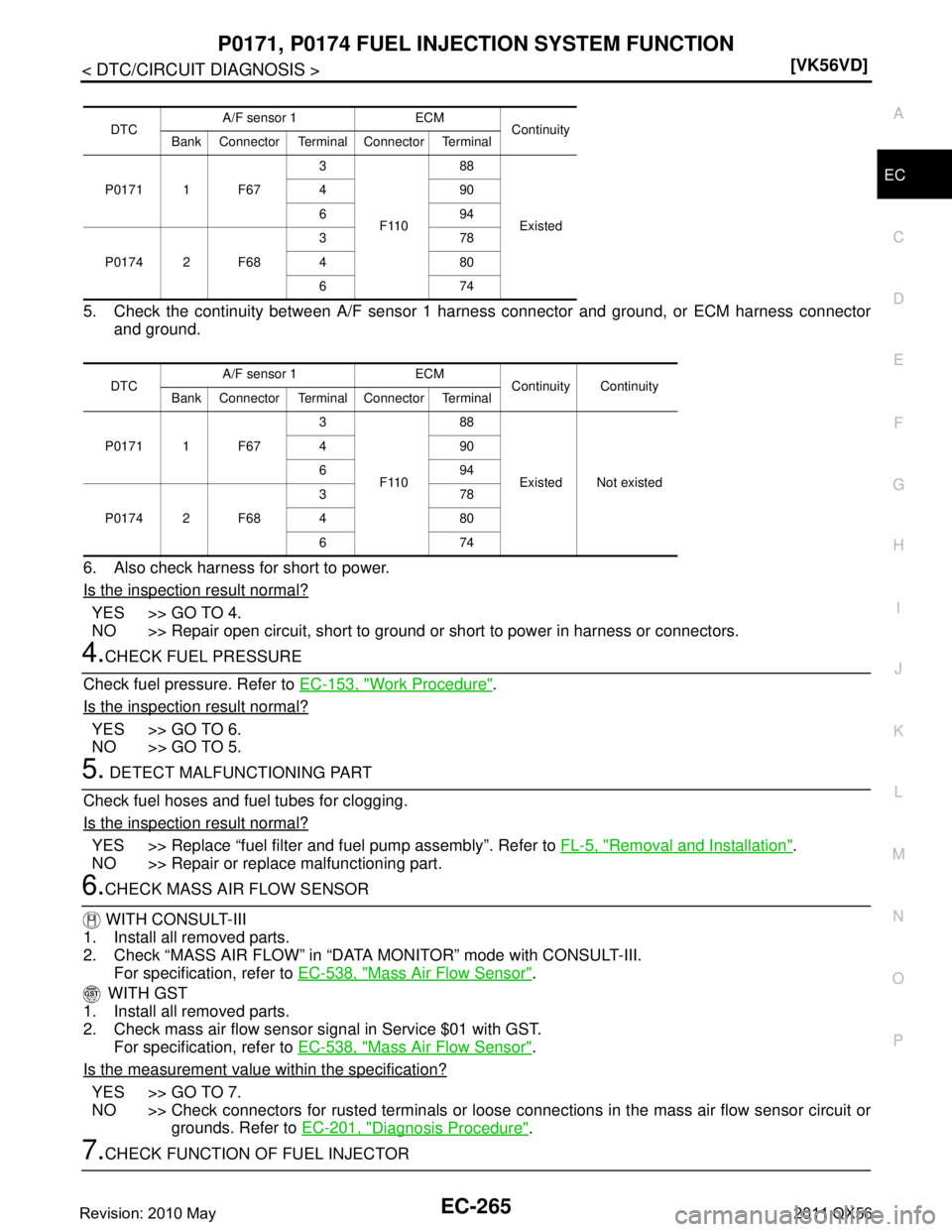
5. Check the continuity between
A/F sensor 1 harness connector and ground, or ECM harness connector
and ground.
6. Also check harness for short to power.
Is the inspection result normal?
YES >> GO TO 4.
NO >> Repair open circuit, short to ground or short to power in harness or connectors.
4.CHECK FUEL PRESSURE
Check fuel pressure. Refer to EC-153, "
Work Procedure".
Is the inspection result normal?
YES >> GO TO 6.
NO >> GO TO 5.
5. DETECT MALFUNCTIONING PART
Check fuel hoses and fuel tubes for clogging.
Is the inspection result normal?
YES >> Replace “fuel filter and fuel pump assembly”. Refer to FL-5, "Removal and Installation".
NO >> Repair or replace malfunctioning part.
6.CHECK MASS AIR FLOW SENSOR
WITH CONSULT-III
1. Install all removed parts.
2. Check “MASS AIR FLOW” in “DATA MONITOR” mode with CONSULT-III.
For specification, refer to EC-538, "
Mass Air Flow Sensor".
WITH GST
1. Install all removed parts.
2. Check mass air flow sensor signal in Service $01 with GST.
For specification, refer to EC-538, "
Mass Air Flow Sensor".
Is the measurement value within the specification?
YES >> GO TO 7.
NO >> Check connectors for rusted terminals or loose c onnections in the mass air flow sensor circuit or
grounds. Refer to EC-201, "
Diagnosis Procedure".
7.CHECK FUNCTION OF FUEL INJECTOR
DTC A/F sensor 1 ECM
Continuity
Bank Connector Terminal Connector Terminal
P0171 1 F67 3
F110 88
Existed
490
694
P0174 2 F68 378
480
674
DTC A/F sensor 1 ECM
Continuity Continuity
Bank Connector Terminal Connector Terminal
P0171 1 F67 3
F110 88
Existed Not existed
490
694
P0174 2 F68 378
480
674
Revision: 2010 May2011 QX56
Page 2293 of 5598
P0172, P0175 FUEL INJECTION SYSTEM FUNCTION
EC-269
< DTC/CIRCUIT DIAGNOSIS > [VK56VD]
C
D
E
F
G H
I
J
K L
M A
EC
NP
O
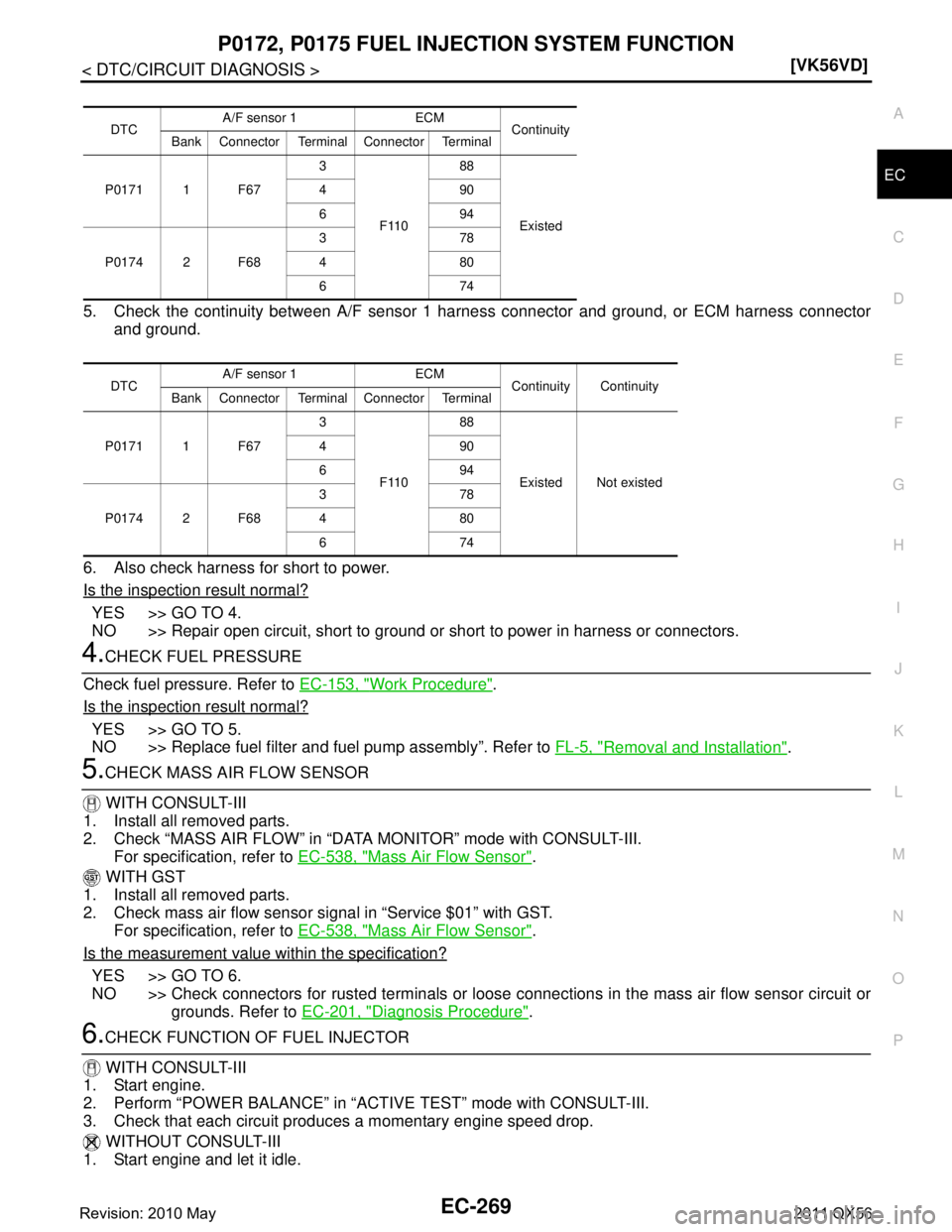
5. Check the continuity between
A/F sensor 1 harness connector and ground, or ECM harness connector
and ground.
6. Also check harness for short to power.
Is the inspection result normal?
YES >> GO TO 4.
NO >> Repair open circuit, short to ground or short to power in harness or connectors.
4.CHECK FUEL PRESSURE
Check fuel pressure. Refer to EC-153, "
Work Procedure".
Is the inspection result normal?
YES >> GO TO 5.
NO >> Replace fuel filter and fuel pump assembly”. Refer to FL-5, "
Removal and Installation".
5.CHECK MASS AIR FLOW SENSOR
WITH CONSULT-III
1. Install all removed parts.
2. Check “MASS AIR FLOW” in “DATA MONITOR” mode with CONSULT-III. For specification, refer to EC-538, "
Mass Air Flow Sensor".
WITH GST
1. Install all removed parts.
2. Check mass air flow sensor signal in “Service $01” with GST. For specification, refer to EC-538, "
Mass Air Flow Sensor".
Is the measurement value within the specification?
YES >> GO TO 6.
NO >> Check connectors for rusted terminals or loose c onnections in the mass air flow sensor circuit or
grounds. Refer to EC-201, "
Diagnosis Procedure".
6.CHECK FUNCTION OF FUEL INJECTOR
WITH CONSULT-III
1. Start engine.
2. Perform “POWER BALANCE” in “A CTIVE TEST” mode with CONSULT-III.
3. Check that each circuit produces a momentary engine speed drop.
WITHOUT CONSULT-III
1. Start engine and let it idle.
DTC A/F sensor 1 ECM
Continuity
Bank Connector Terminal Connector Terminal
P0171 1 F67 3
F110 88
Existed
490
694
P0174 2 F68 378
480
674
DTC A/F sensor 1 ECM
Continuity Continuity
Bank Connector Terminal Connector Terminal
P0171 1 F67 3
F110 88
Existed Not existed
490
694
P0174 2 F68 378
480
674
Revision: 2010 May2011 QX56
Page 2296 of 5598
EC-272
< DTC/CIRCUIT DIAGNOSIS >[VK56VD]
P0181 FTT SENSOR
NO >> Proceed to
MWI-69, "Component Function Check".
2.CHECK FUEL TANK TEMPERATURE SENSOR POWER SUPPLY CIRCUIT
1. Turn ignition switch OFF.
2. Disconnect “fuel level sensor uni t and fuel pump” harness connector.
3. Turn ignition switch ON.
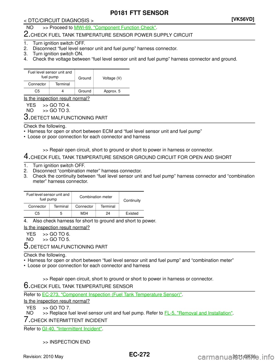
4. Check the voltage between “fuel level sensor unit and fuel pump” harness connector and ground.
Is the inspection result normal?
YES >> GO TO 4.
NO >> GO TO 3.
3.DETECT MALFUNCTIONING PART
Check the following.
Harness for open or short between ECM and “fuel level sensor unit and fuel pump”
Loose or poor connection for each connector and harness
>> Repair open circuit, short to ground or short to power in harness or connector.
4.CHECK FUEL TANK TEMPERATURE SENSOR GROUND CIRCUIT FOR OPEN AND SHORT
1. Turn ignition switch OFF.
2. Disconnect “combination meter” harness connector.
3. Check the continuity between “fuel level sensor unit and fuel pump” harness connector and “combination
meter” harness connector.
4. Also check harness for short to ground and short to power.
Is the inspection result normal?
YES >> GO TO 6.
NO >> GO TO 5.
5.DETECT MALFUNCTIONING PART
Check the following.
Harness for open or short between “fuel level s ensor unit and fuel pump” and “combination meter”
Loose or poor connection for each connector and harness
>> Repair open circuit, short to ground or short to power in harness or connector.
6.CHECK FUEL TANK TEMPERATURE SENSOR
Refer to EC-273, "
Component Inspection (Fuel Tank Temperature Sensor)".
Is the inspection result normal?
YES >> GO TO 7.
NO >> Replace fuel level sensor unit and fuel pump. Refer to FL-5, "
Removal and Installation".
7.CHECK INTERMITTENT INCIDENT
Refer to GI-40, "
Intermittent Incident".
>> INSPECTION END
Fuel level sensor unit and fuel pump Ground Voltage (V)
Connector Terminal
C5 4 Ground Approx. 5
Fuel level sensor unit and fuel pump Combination meter
Continuity
Connector Terminal Connector Terminal
C5 5 M34 24 Existed
Revision: 2010 May2011 QX56
Page 2297 of 5598
P0181 FTT SENSOREC-273
< DTC/CIRCUIT DIAGNOSIS > [VK56VD]
C
D
E
F
G H
I
J
K L
M A
EC
NP
O
Component Inspection (Fuel
Tank Temperature Sensor)INFOID:0000000006288291
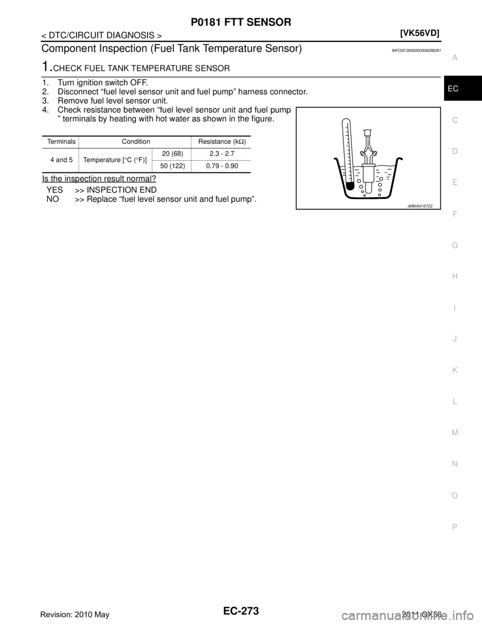
1.CHECK FUEL TANK TEMPERATURE SENSOR
1. Turn ignition switch OFF.
2. Disconnect “fuel level sensor unit and fuel pump” harness connector.
3. Remove fuel level sensor unit.
4. Check resistance between “fuel level sensor unit and fuel pump ” terminals by heating with hot water as shown in the figure.
Is the inspection result normal?
YES >> INSPECTION END
NO >> Replace “fuel level sensor unit and fuel pump”.
Terminals Condition Resistance (k Ω)
4 and 5 Temperature [ °C ( °F)] 20 (68) 2.3 - 2.7
50 (122) 0.79 - 0.90
JMBIA0167ZZ
Revision: 2010 May2011 QX56
Page 2298 of 5598
EC-274
< DTC/CIRCUIT DIAGNOSIS >[VK56VD]
P0182, P0183 FTT SENSOR
P0182, P0183 FTT SENSOR
DTC LogicINFOID:0000000006288292
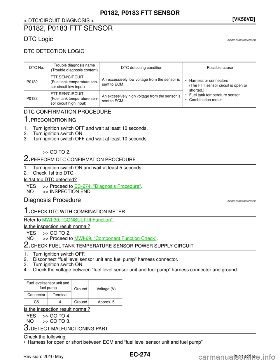
DTC DETECTION LOGIC
DTC CONFIRMATION PROCEDURE
1.PRECONDITIONING
1. Turn ignition switch OFF and wait at least 10 seconds.
2. Turn ignition switch ON.
3. Turn ignition switch OFF and wait at least 10 seconds.
>> GO TO 2.
2.PERFORM DTC CONFIRMATION PROCEDURE
1. Turn ignition switch ON and wait at least 5 seconds.
2. Check 1st trip DTC.
Is 1st trip DTC detected?
YES >> Proceed to EC-274, "Diagnosis Procedure".
NO >> INSPECTION END
Diagnosis ProcedureINFOID:0000000006288293
1.CHECK DTC WITH COMBINATION METER
Refer to MWI-30, "
CONSULT-III Function".
Is the inspection result normal?
YES >> GO TO 2.
NO >> Proceed to MWI-69, "
Component Function Check".
2.CHECK FUEL TANK TEMPERATURE SENSOR POWER SUPPLY CIRCUIT
1. Turn ignition switch OFF.
2. Disconnect “fuel level sensor uni t and fuel pump” harness connector.
3. Turn ignition switch ON.
4. Check the voltage between “fuel level sensor unit and fuel pump” harness connector and ground.
Is the inspection result normal?
YES >> GO TO 4.
NO >> GO TO 3.
3.DETECT MALFUNCTIONING PART
Check the following.
Harness for open or short between ECM and “fuel level sensor unit and fuel pump”
DTC No.Trouble diagnosis name
(Trouble diagnosis content) DTC detecting condition Possible cause
P0182 FTT SEN/CIRCUIT
(Fuel tank temperature sen-
sor circuit low input) An excessively low voltage from the sensor is
sent to ECM.
Harness or connectors
(The FTT sensor circuit is open or
shorted.)
Fuel tank temperature sensor
Combination meter
P0183 FTT SEN/CIRCUIT
(Fuel tank temperature sen-
sor circuit high input) An excessively high voltage from the sensor is
sent to ECM.
Fuel level sensor unit and
fuel pump Ground Voltage (V)
Connector Terminal
C5 4 Ground Approx. 5
Revision: 2010 May2011 QX56