2011 INFINITI QX56 rear suspension
[x] Cancel search: rear suspensionPage 1 of 5598
A
B
D
E
F
G
H
I
J
K
L
M
N
P
O
C
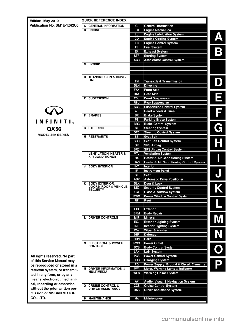
QUICK REFERENCE INDEX
AGENERAL INFORMATIONGIGeneral Information
BENGINEEMEngine Mechanical
LUEngine Lubrication System
COEngine Cooling System
ECEngine Control System
FLFuel System
EXExhaust System
STRStarting System
ACCAccelerator Control System
CHYBRIDHBCHybrid Control System
HBBHybrid Battery System
HBRHybrid Brake System
DTRANSMISSION & DRIVE-
LINECLClutch
TMTransaxle & Transmission
DLNDriveline
FAXFront Axle
RAXRear Axle
ESUSPENSIONFSUFront Suspension
RSURear Suspension
SCSSuspension Control System
WTRoad Wheels & Tires
FBRAKESBRBrake System
PBParking Brake System
BRCBrake Control System
GSTEERINGSTSteering System
STCSteering Control System
HRESTRAINTSSBSeat Belt
SBCSeat Belt Control System
SRSRS Airbag
SRCSRS Airbag Control System
IVENTILATION, HEATER &
AIR CONDITIONERVTLVentilation System
HAHeater & Air Conditioning System
HACHeater & Air Conditioning Control System
JBODY INTERIORINTInterior
IPInstrument Panel
SESeat
ADPAutomatic Drive Positioner
KBODY EXTERIOR,
DOORS, ROOF & VEHICLE
SECURITYDLKDoor & Lock
SECSecurity Control System
GWGlass & Window System
PWCPower Window Control System
RFRoof
HDHood
EXTExterior
BRMBody Repair
LDRIVER CONTROLSMIRMirrors
EXLExterior Lighting System
INLInterior Lighting System
WWWiper & Washer
DEFDefogger
HRNHorn
MELECTRICAL & POWER
CONTROLPWOPower Outlet
BCSBody Control System
LANLAN System
PCSPower Control System
CHGCharging System
PGPower Supply, Ground & Circuit Elements
NDRIVER INFORMATION &
MULTIMEDIAMWIMeter, Warning Lamp & Indicator
WCSWarning Chime System
SNSonar System
AVAudio, Visual & Navigation System
OCRUISE CONTROL &
DRIVER ASSISTANCECCSCruise Control System
DASDriver Assistance System
DMSDrive Mode System
PMAINTENANCEMAMaintenance
All rights reserved. No part
of this Service Manual may
be reproduced or stored in a
retrieval system, or transmit-
ted in any form, or by any
means, electronic, mechani-
cal, recording or otherwise,
without the prior written per-
mission of NISSAN MOTOR
CO., LTD.
Edition: May 2010
Publication No. SM1E-1Z62U0
Page 523 of 5598

BRC-6
< PRECAUTION >[WITH VDC]
PRECAUTIONS
5. When the repair work is completed, re-connect bot
h battery cables. With the brake pedal released, turn
the push-button ignition switch from ACC position to ON position, then to LOCK position. (The steering
wheel will lock when the push-button igniti on switch is turned to LOCK position.)
6. Perform self-diagnosis check of all control units using CONSULT-III.
Precaution for Procedure without Cowl Top CoverINFOID:0000000006228176
When performing the procedure after removing cowl top cover, cover
the lower end of windshield with urethane, etc.
Precaution for Brake SystemINFOID:0000000006222556
WARNING:
Clean any dust from the front brake and rear brake using a vacuum dust collector. Never blow by com-
pressed air.
Brake fluid use refer to MA-10, "
Fluids and Lubricants".
Never reuse drained brake fluid.
Never spill or splash brake fluid on painted surfaces. Brake fluid may seriously damage paint. Wipe it off
immediately and wash with water if it gets on a painted surface.
Always confirm the specified tightening torque when installing the brake pipes.
After pressing the brake pedal more deeply or harder t han normal driving, such as air bleeding, check each
item of brake pedal. Adjust brake pedal if it is outside the standard value.
Never use mineral oils such as gasoline or light oil to clean. They may damage rubber parts and cause
improper operation.
Always loosen the brake tube flar e nut with a flare nut wrench.
Tighten the brake tube flare nut to the specified torque with a crow-
foot (A) and torque wrench (B).
Always connect the battery terminal when moving the vehicle.
Turn the ignition switch OFF and disconnect the ABS actuator and
electric unit (control unit) harness connector or the battery negative
terminal before performing the work.
Check that no brake fluid leakage is present after replacing the parts.
Precaution for Brak e Control SystemINFOID:0000000006222557
Slight vibrations are felt on the brake pedal and the operation noises occur, when VDC function, TCS func-
tion, ABS function, EBD function, hill start assist function or brake limited slip differential (BLSD) function
operates. This is not a malfunction because it is caus ed by VDC function, TCS function, ABS function, EBD
function, hill start assist function or brake limited sl ip differential (BLSD) function that is normally operated.
When starting engine or when starting vehicle just after starting engine, brake pedal may vibrate or motor
operating noise may be heard from engine compartment. This is normal condition.
Brake stopping distance may become longer than models without ABS function depending on the road con-
ditions, when ABS function is operated on slippery r oad like rough road, gravel road or snowy road.
When a malfunction is indicated, always collect info rmation from the customer about conditions of occur-
rence, estimate cause and perform operation. Check brake booster operation, brake fluid level and brake
fluid leakage, as well as electrical system.
The optimum performance is achieved by control for V DC function, TCS function, ABS function, EBD func-
tion, hill start assist function or brake limited slip di fferential (BLSD) function when all of brakes, suspensions
PIIB3706J
JPFIA0001ZZ
Revision: 2010 May2011 QX56
Page 524 of 5598

PRECAUTIONSBRC-7
< PRECAUTION > [WITH VDC]
C
D
E
G H
I
J
K L
M A
B
BRC
N
O P
and tires installed on the vehicle are the specified si ze and parts. Brake performance and controllability may
be negatively affected when other parts than the specified are installed.
Brake stopping distance may become longer and steering stability may be negatively affected, when tires in
different size and combination or other parts than the specified are used.
When a radio (including wiring), antenna and antenna lead line are located near ABS actuator and electric
unit (control unit), a malfunction or improper operation ma y occur for the control of VDC function, TCS func-
tion, ABS function, EBD function, hill start assist func tion or brake limited slip differential (BLSD) function.
When the following items are replaced by other parts than genuine parts or modified, ABS warning lamp, brake warning lamp and VDC warning lamp may turn ON, and the control may not operate normally for VDC
function, TCS function, ABS function, EB D function, hill start assist function or brake limited slip differential
(BLSD) function.
- Suspension component parts (shock absorber, spring, bushing and others)
- Tire and wheel (other than the specified size)
- Brake component parts (brake pad, disc rotor, brake caliper and others)
- Engine component parts (ECM, muffler and others)
- Body reinforcement component parts (rollover bar, tower bar and others)
When suspension, tire and brake component parts are excessively worn or deteriorated and the vehicle is
driven, ABS warning lamp, brake warning lamp and VDC warning lamp may tu\
rn ON, and the control may
not operate normally for VDC function, TCS function, ABS function, EBD function, hill start assist function or
brake limited slip differential (BLSD) function.
ABS warning lamp, brake warning lamp and VDC warning lamp may turn ON, when only front wheel or rear wheel is rotated using a free roller. This is not a ma lfunction, because it is caused by wheel speed difference
between wheel that is rotated and wheel that is not rota ted. In this case, perform self-diagnosis, check self-
diagnosis results, and erase memory.
When power supply voltage is not normal, ABS warning lamp, brake warning lamp and VDC warning lamp
turn ON. ABS actuator and electric unit (control unit) st ops control for VDC function, TCS function, ABS func-
tion, EBD function, hill start assist function or brake limited slip differential (BLSD) function. Ordinary brake
operates. After power supply returns to normal, ABS warning lamp, brake warning lamp and VDC warning
lamp turn OFF. The control becomes operative for VD C function, TCS function, ABS function, EBD function,
hill start assist function or brake li mited slip differential (BLSD) function.
VDC warning lamp may turn ON and VDC function or TCS function may not normally operate, when driving
on a special road the is extremely slanted (bank in a circ uit course). This is not a malfunction if the status
returns to normal for VDC function or TCS function after the engine is started again. In this case, perform
self-diagnosis, check self-diagnosis results, and erase memory.
A malfunction in yaw rate/side/decel G sensor syste m may be detected when the vehicle sharply turns dur-
ing a spin turn, acceleration turn or drift driving while VDC function or TCS function are OFF (VDC OFF
switch is pressed and VDC OFF indicator lamp is in ON st atus). This is not a malfunction if the status returns
to normal for VDC function or TCS function after the engine is started again. In this case, perform self-diag-
nosis, check self-diagnosis results, and erase memory
Precaution for Harness RepairINFOID:0000000006222558
Solder the repair part, and wrap it with tape. [Twisted wire fray must be 110 mm (4.33 in) or less.]
SKIB8766E
Revision: 2010 May2011 QX56
Page 679 of 5598

BRM-4
< PRECAUTION >
REPAIRING HIGH STRENGTH STEEL
PRECAUTION
REPAIRING HIGH STRENGTH STEEL
High Strength Steel (HSS)INFOID:0000000006248484
High strength steel is used for body panels in order to reduce vehicle weight.
Accordingly, precautions in repairing automotive bodies made of high strength steel are described below:
Read the following precautions when repairing HSS:
1. Additional points to consider
Tensile strength Major applicable parts 440 - 780 MPa Rear floor reinforcement
2nd seat mounting member assembly
Front seat mounting rear crossmember assembly
Front floor reinforcement
2nd crossmember (Lower)
Side radiator core support
Radiator core support main assembly
Front side member assembly
4th crossmember
2nd seat mounting crossmember
Rear side member
Rear crossmember
Inner side roof rail
Upper inner front pillar
Inner center pillar
Upper front pillar reinforcement
Lower center pillar brace
Front pillar brace
Outer sill reinforcement
Front roof rail
Rear roof rail
Radiator guard crossmember assembly
2nd crossmember assembly
2nd crossmember reinforcement
Front side member assembly
Front bound bumper bracket assembly
Lower front link mounting bracket assembly
Center side member assembly
Fuel tank protector assembly
Rear suspension mounting bracket assembly
Rear shock absorber bracket assembly
Rear side member assembly
Rear end gusset
Rear end crossmember assembly
980 - 1350 MPa Lower dash center reinforcement
(Lower dash Component part)
Inner sill
Rear seat crossmember
(2nd seat mounting crossmember component part)
Inner center pillar (Upper)
Upper outer center pillar reinforcement
(Lower center pillar brace component part)
Front bumper crossmember assembly
Revision: 2010 May2011 QX56
Page 689 of 5598
BRM-14
< PREPARATION >
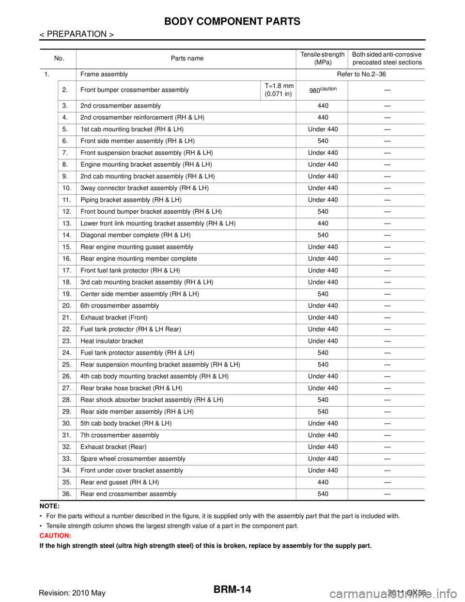
BODY COMPONENT PARTS
NOTE:
For the parts without a number described in the figure, it is supplied only with the assembly part that the part is included with.
Tensile strength column shows the largest strength value of a part in the component part.
CAUTION:
If the high strength steel (ultra high strength steel) of this is broken, replace by assembly for the supply part. No. Parts name
Tensile strength
(MPa) Both sided anti-corrosive
precoated steel sections
1. Frame assembly Refer to No.2−36
2. Front bumper crossmember assembly T=1.8 mm
(0.071 in)
980
caution—
3. 2nd crossmember assembly 440 —
4. 2nd crossmember reinforcement (RH & LH) 440 —
5. 1st cab mounting bracket (RH & LH) Under 440 —
6. Front side member assembly (RH & LH) 540 —
7. Front suspension bracket assembly (RH & LH) Under 440 —
8. Engine mounting bracket assembly (RH & LH) Under 440 —
9. 2nd cab mounting bracket assembly (RH & LH) Under 440 —
10. 3way connector bracket assembly (RH & LH) Under 440 —
11. Piping bracket assembly (RH & LH) Under 440 —
12. Front bound bumper bracket assembly (RH & LH) 540 —
13. Lower front link mounting bracket assembly (RH & LH) 440 —
14. Diagonal member complete (RH & LH) 540 —
15. Rear engine mounting gusset assembly Under 440 —
16. Rear engine mounting member complete Under 440 —
17. Front fuel tank protector (RH & LH) Under 440 —
18. 3rd cab mounting bracket assembly (RH & LH) Under 440 —
19. Center side member assembly (RH & LH) 540 —
20. 6th crossmember assembly Under 440 —
21. Exhaust bracket (Front) Under 440 —
22. Fuel tank protector (RH & LH Rear) Under 440 —
23. Heat insulator bracket Under 440 —
24. Fuel tank protector assembly (RH & LH) 540 —
25. Rear suspension mounting bracket assembly (RH & LH) 540 —
26. 4th cab body mounting bracket assembly (RH & LH) Under 440 —
27. Rear brake hose bracket (RH & LH) Under 440 —
28. Rear shock absorber bracket assembly (RH & LH) 540 —
29. Rear side member assembly (RH & LH) 540 —
30. 5th cab body bracket (RH & LH) Under 440 —
31. 7th crossmember assembly Under 440 —
32. Exhaust bracket (Rear) Under 440 —
33. Spare wheel crossmember assembly Under 440 —
34. Front under cover bracket assembly Under 440 —
35. Rear end gusset (RH & LH) 440 —
36. Rear end crossmember assembly 540 —
Revision: 2010 May2011 QX56
Page 1918 of 5598

DLN-116
< REMOVAL AND INSTALLATION >[TRANSFER: ATX90A]
TRANSFER HI-LO POSITION SENSOR
TRANSFER HI-LO POSITION SENSOR
Exploded ViewINFOID:0000000006222337
Removal and InstallationINFOID:0000000006222338
REMOVAL
1. Turn the ignition switch OFF.
2. Disconnect negative battery terminal.
CAUTION:
Wait for 5 seconds after turn ing ignition switch OFF.
3. Remove exhaust front tube (LH). Refer to EX-5, "
Removal and Installation".
4. Support transfer assembly and transmission assembly with a jack.
5. Remove front suspension rear cross member with a power tool. Refer to TM-208, "
4WD : Removal and
Installation".
6. Remove rear engine mounting cross member with a power tool. Refer to TM-208, "
4WD : Removal and
Installation".
7. Remove heat insulator of exhaust front tube (LH).
8. Lower jack to the position where the tr ansfer Hi-Lo position sensor can be removed.
9. Disconnect the transfer Hi-Lo position sensor connector.
10. Remove the transfer Hi-Lo position sensor.
11. Perform inspection after removal. Refer to DLN-116, "
Inspection".
INSTALLATION
Note the following, and install in the reverse order of removal.
Never damage O-ring of transfer Hi-Lo position sensor.
Perform inspection after installation. Refer to DLN-116, "
Inspection".
InspectionINFOID:0000000006222339
INSPECTION AFTER REMOVAL
Check the O-ring assembled transfer Hi-Lo position sens or for wear, crack and damage. Replace the transfer
Hi-Lo position sensor if there is malfunction.
INSPECTION AFTER INSTALLATION
After driving, check the surface fitting transfer Hi-Lo position sensor to transfer assembly for fluid leakage.
1. Transfer Hi-Lo position sensor 2. Transfer assembly
: Vehicle front
Refer to GI-4, "
Components" for symbols not described above.
JPDIE0282GB
Revision: 2010 May2011 QX56
Page 1919 of 5598

TRANSFER ROTARY POSITION SENSORDLN-117
< REMOVAL AND INSTALLATION > [TRANSFER: ATX90A]
C
EF
G H
I
J
K L
M A
B
DLN
N
O P
TRANSFER ROTARY POSITION SENSOR
Exploded ViewINFOID:0000000006222340
Removal and InstallationINFOID:0000000006222341
REMOVAL
1. Turn the ignition switch OFF.
2. Disconnect negative battery terminal. CAUTION:
Wait for 5 seconds after turning ignition switch OFF.
3. Support transfer assembly and transmission assembly with a jack.
4. Remove front suspension rear cross member with a power tool. Refer to TM-208, "
4WD : Removal and
Installation".
5. Remove rear engine mounting cross member with a power tool. Refer to TM-208, "
4WD : Removal and
Installation".
6. Disconnect the transfer rotary position sensor connector.
7. Remove the transfer rotary position sensor.
8. Perform inspection after removal. Refer to DLN-118, "
Inspection".
INSTALLATION
1. Remove the transfer control actuator. Refer to DLN-114, "Exploded View"
2. Shift transfer assembly into AUTO as follows.
a. Install the spline socket (A) [SST: KV10119400 ( — )] to
transfer assembly in the figure.
b. Turn the shaft (B) direction and remove the spline socket at a position returning to (C) direction by spring power.
CAUTION:
The maximum turning force shall be 30 N·m (3.1 kg-m, 22 ft-
lb).
1. Transfer assembly 2. Transfer rotary position sensor
: Vehicle front
Refer to GI-4, "
Components" for symbols not described above.
JPDIE0283GB
JPDIE0184ZZ
Revision: 2010 May2011 QX56
Page 1928 of 5598

DLN-126
< SYMPTOM DIAGNOSIS >[FRONT PROPELLER SHAFT: 2F P15]
NOISE, VIBRATION, AND HARSHNESS
(NVH) TROUBLESHOOTING
SYMPTOM DIAGNOSIS
NOISE, VIBRATION, AND HARSHNESS (NVH) TROUBLESHOOTING
NVH Troubleshooting ChartINFOID:0000000006222354
Use the chart below to help you find the cause of the symptom. If necessa ry, repair or replace these parts.
×: ApplicableReference
DLN-127, "
Inspection
"—
—
—
—
DLN-127, "
Inspection
"
DLN-127, "
Inspection
"
NVH of FRONT FINAL DRI VE in this section.
NVH of REAR FINAL DRI VE in this section.
NVH in FAX, RAX, FSU and RSU section.
NVH in WT section.
NVH in WT section.
NVH in FAX and RAX section.
NVH in BR section.
NVH in ST section.
Possible cause an d SUSPECTED PARTS
Uneven rotating torque
Center bearing improper installation
Excessive center bearing axial end play
Center bearing mounting (insulator) cracks, damage or deterioration
Excessive joint angle
Rotation imbalance
Excessive runout
DIFFERENTIAL
AXLE AND SUSPENSION
TIRE
ROAD WHEEL
DRIVE SHAFT
BRAKE
STEERING
Symptom Noise
××××××××××××××
Shake × × ××××××
Vibration ××××××× ×× × ×
Revision: 2010 May2011 QX56