2011 INFINITI QX56 fuse
[x] Cancel search: fusePage 4753 of 5598
![INFINITI QX56 2011 Factory Service Manual
SEC-146
< DTC/CIRCUIT DIAGNOSIS >[WITH INTELLIGENT KEY SYSTEM]
SECURITY INDICATOR LAMP
SECURITY INDICATOR LAMP
Component Function CheckINFOID:0000000006226312
1.CHECK FUNCTION
1. Perform “THEFT IND INFINITI QX56 2011 Factory Service Manual
SEC-146
< DTC/CIRCUIT DIAGNOSIS >[WITH INTELLIGENT KEY SYSTEM]
SECURITY INDICATOR LAMP
SECURITY INDICATOR LAMP
Component Function CheckINFOID:0000000006226312
1.CHECK FUNCTION
1. Perform “THEFT IND](/manual-img/42/57033/w960_57033-4752.png)
SEC-146
< DTC/CIRCUIT DIAGNOSIS >[WITH INTELLIGENT KEY SYSTEM]
SECURITY INDICATOR LAMP
SECURITY INDICATOR LAMP
Component Function CheckINFOID:0000000006226312
1.CHECK FUNCTION
1. Perform “THEFT IND” in “ACTIVE TEST” m ode of “IMMU” of “BCM” using CONSULT-III.
2. Check security indicator lamp operation.
Is the inspection result normal?
YES >> INSPECTION END
NO >> Go to SEC-146, "
Diagnosis Procedure".
Diagnosis ProcedureINFOID:0000000006226313
1.CHECK SECURITY INDICATOR LA MP POWER SUPPLY CIRCUIT
1. Turn ignition switch OFF.
2. Disconnect combination meter connector.
3. Check voltage between combination meter harness connector and ground.
Is the inspection result normal?
YES >> GO TO 2.
NO-1 >> Check 10 A fuse [No. 11, located in the fuse block (J/B)].
NO-2 >> Check harness for open or short between combination meter and fuse.
2.CHECK SECURITY INDI CATOR LAMP SIGNAL
1. Connect combination meter connector.
2. Disconnect BCM connector.
3. Check voltage between BCM harness connector and ground.
Is the inspection result normal?
YES >> GO TO 3.
NO >> GO TO 4.
3.REPLACE BCM
1. Replace BCM. Refer to BCS-81, "
Removal and Installation".
2. Perform initialization of BCM and registration of all Intelligent Keys using CONSULT-III.
For initialization and registration procedures, refer to CONSULT-III Operation Manual NATS-IVIS/NVIS.
>> INSPECTION END
4.CHECK SECURITY INDI CATOR LAMP CIRCUIT
1. Disconnect combination meter connector.
2. Check continuity between combination meter harness connector and BCM harness connector.
Te s t i t e m D e s c r i p t i o n
THEFT IND ON
Security indicator lamp Illuminates
OFF Does not illuminate
(+) (–)Voltage (V)
(Approx.)
Combination meter
Connector Terminal M34 1 Ground Battery voltage
(+) (–)Voltage (V)
(Approx.)
BCM
Connector Terminal
M68 23 Ground Battery voltage
Revision: 2010 May2011 QX56
Page 4986 of 5598
SRS AIR BAG WARNING LAMP DOES NOT TURN OFF
SRC-193
< SYMPTOM DIAGNOSIS >
C
D E
F
G
I
J
K L
M A
B
SRC
N
O P
SYMPTOM DIAGNOSIS
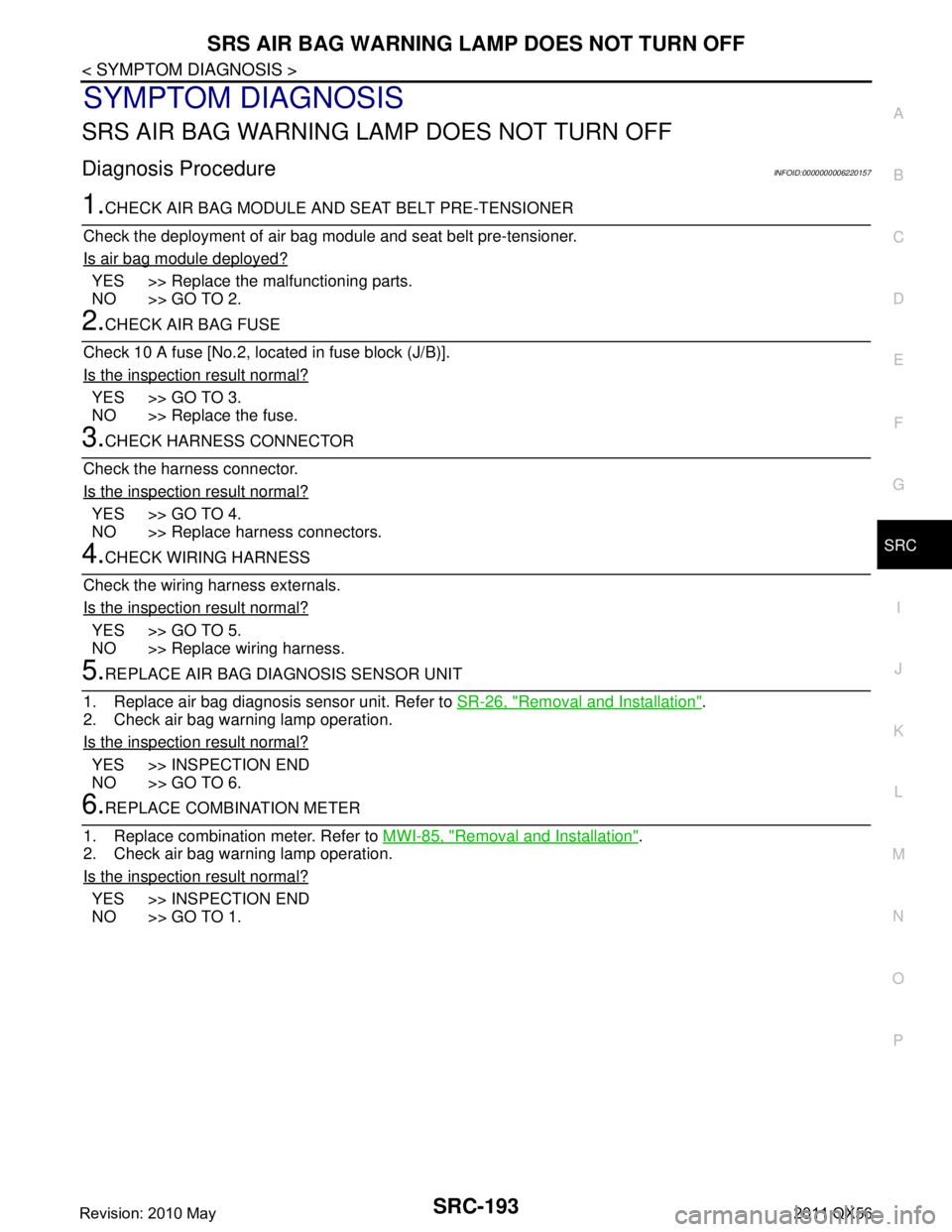
SRS AIR BAG WARNING LAMP DOES NOT TURN OFF
Diagnosis ProcedureINFOID:0000000006220157
1.CHECK AIR BAG MODULE AND SEAT BELT PRE-TENSIONER
Check the deployment of air bag m odule and seat belt pre-tensioner.
Is air bag module deployed?
YES >> Replace the malfunctioning parts.
NO >> GO TO 2.
2.CHECK AIR BAG FUSE
Check 10 A fuse [No.2, located in fuse block (J/B)].
Is the inspection result normal?
YES >> GO TO 3.
NO >> Replace the fuse.
3.CHECK HARNESS CONNECTOR
Check the harness connector.
Is the inspection result normal?
YES >> GO TO 4.
NO >> Replace harness connectors.
4.CHECK WIRING HARNESS
Check the wiring harness externals.
Is the inspection result normal?
YES >> GO TO 5.
NO >> Replace wiring harness.
5.REPLACE AIR BAG DIAGNOSIS SENSOR UNIT
1. Replace air bag diagnosis sensor unit. Refer to SR-26, "
Removal and Installation".
2. Check air bag warning lamp operation.
Is the inspection result normal?
YES >> INSPECTION END
NO >> GO TO 6.
6.REPLACE COMBINATION METER
1. Replace combination meter. Refer to MWI-85, "
Removal and Installation".
2. Check air bag warning lamp operation.
Is the inspection result normal?
YES >> INSPECTION END
NO >> GO TO 1.
Revision: 2010 May2011 QX56
Page 5004 of 5598
HEATED STEERING WHEEL SYSTEMST-17
< DTC/CIRCUIT DIAGNOSIS >
C
DE
F
H I
J
K L
M A
B
ST
N
O P
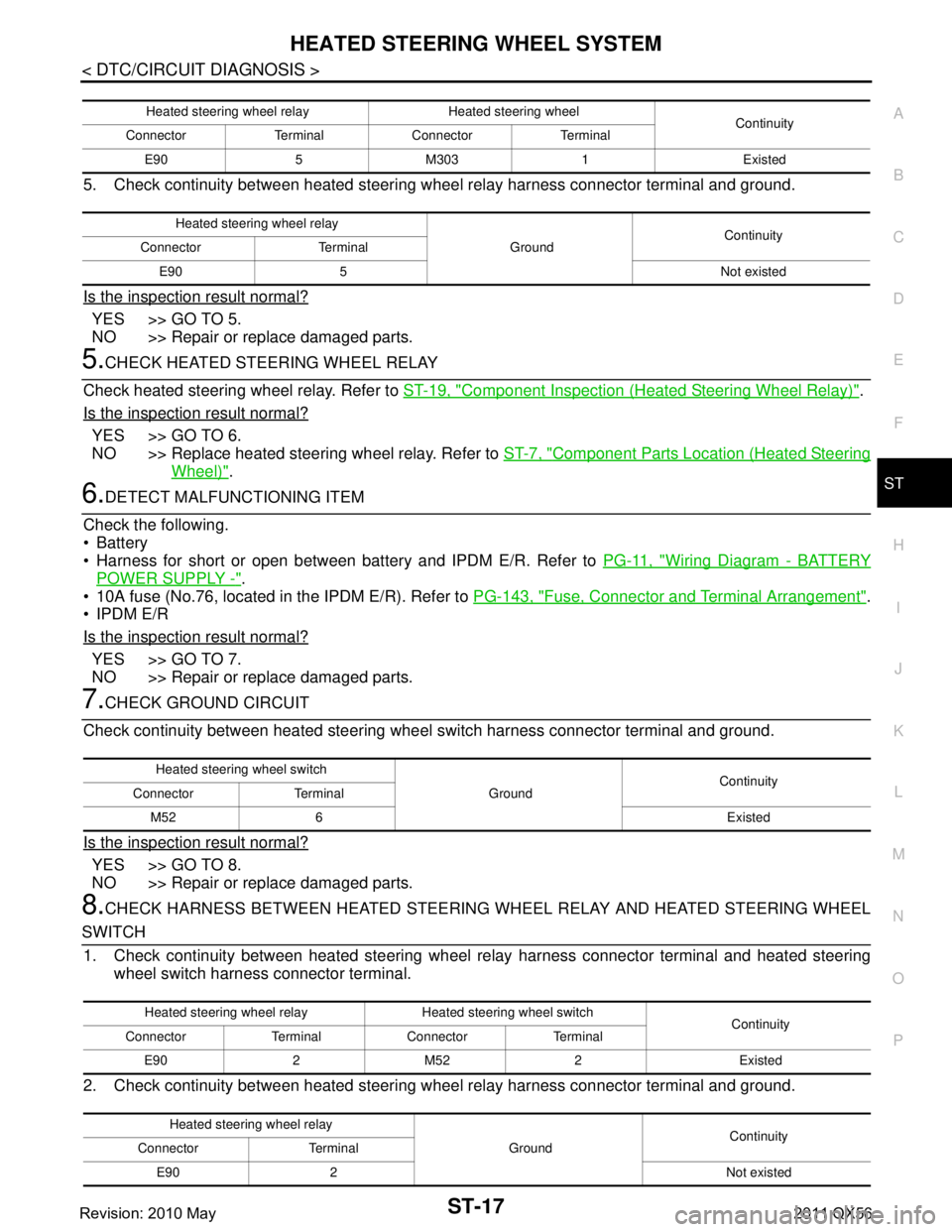
5. Check continuity between heated steering w heel relay harness connector terminal and ground.
Is the inspection result normal?
YES >> GO TO 5.
NO >> Repair or replace damaged parts.
5.CHECK HEATED STEERING WHEEL RELAY
Check heated steering wheel relay. Refer to ST-19, "
Component Inspection (Heated Steering Wheel Relay)".
Is the inspection result normal?
YES >> GO TO 6.
NO >> Replace heated steering wheel relay. Refer to ST-7, "
Component Parts Location (Heated Steering
Wheel)".
6.DETECT MALFUNCTIONING ITEM
Check the following.
Battery
Harness for short or open between bat tery and IPDM E/R. Refer to PG-11, "
Wiring Diagram - BATTERY
POWER SUPPLY -".
10A fuse (No.76, located in the IPDM E/R). Refer to PG-143, "
Fuse, Connector and Terminal Arrangement".
IPDM E/R
Is the inspection result normal?
YES >> GO TO 7.
NO >> Repair or replace damaged parts.
7.CHECK GROUND CIRCUIT
Check continuity between heated steering wheel switch harness connector terminal and ground.
Is the inspection result normal?
YES >> GO TO 8.
NO >> Repair or replace damaged parts.
8.CHECK HARNESS BETWEEN HEATED STEERING WHEEL RELAY AND HEATED STEERING WHEEL
SWITCH 1. Check continuity between heated steering wheel relay harness connector terminal and heated steering
wheel switch harness connector terminal.
2. Check continuity between heated steering w heel relay harness connector terminal and ground.
Heated steering wheel relay Heated steering wheel
Continuity
Connector Terminal Connector Terminal
E90 5 M303 1 Existed
Heated steering wheel relay GroundContinuity
Connector Terminal
E90 5 Not existed
Heated steering wheel switch GroundContinuity
Connector Terminal
M52 6 Existed
Heated steering wheel relay Heated steering wheel switch Continuity
Connector Terminal Connector Terminal
E90 2 M52 2 Existed
Heated steering wheel relay GroundContinuity
Connector Terminal
E90 2 Not existed
Revision: 2010 May2011 QX56
Page 5005 of 5598
ST-18
< DTC/CIRCUIT DIAGNOSIS >
HEATED STEERING WHEEL SYSTEM
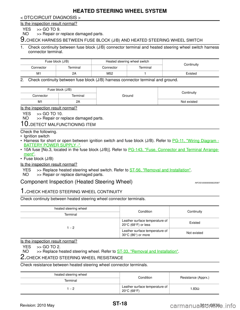
Is the inspection result normal?
YES >> GO TO 9.
NO >> Repair or replace damaged parts.
9.CHECK HARNESS BETWEEN FUSE BLOCK (J/B) AND HEATED STEERING WHEEL SWITCH
1. Check continuity between fuse block (J/B) connec tor terminal and heated steering wheel switch harness
connector terminal.
2. Check continuity between fuse block (J/B) harness connector terminal and ground.
Is the inspection result normal?
YES >> GO TO 10.
NO >> Repair or replace damaged parts.
10.DETECT MALFUNCTIONING ITEM
Check the following.
Ignition switch
Harness for short or open between ignition switch and fuse block (J/B). Refer to PG-11, "
Wiring Diagram -
BATTERY POWER SUPPLY -".
10A fuse [No.3, located in the fuse block (J/B)]. Refer to PG-143, "
Fuse, Connector and Terminal Arrange-
ment".
Fuse block (J/B)
Is the inspection result normal?
YES >> Replace heated steering wheel switch. Refer to ST-56, "Removal and Installation".
NO >> Repair or replace damaged parts.
Component Inspection (Heated Steering Wheel)INFOID:0000000006225587
1.CHECK HEATED STEERING WHEEL CONTINUITY
Check continuty between heated steering wheel connector terminals.
Is the inspection result normal?
YES >> GO TO 2.
NO >> Replace heated steering wheel. Refer to ST-33, "
Removal and Installation".
2.CHECK HEATED STEERING WHEEL RESISTANCE
Check resistance between heated steering wheel connector terminals.
Fuse block (J/B) Heated steering wheel switch Continuity
Connector Terminal Connector Terminal
M1 2A M52 1 Existed
Fuse block (J/B) GroundContinuity
Connector Terminal
M1 2A Not existed
heated steering wheel Condition Continuity
Terminal
1 − 2 Leather surface temperature of
20
°C (68 °F) or less Existed
Leather surface temperature of
30 °C (86 °) or more Not existed
heated steering wheel
Condition Resistance (Apprx.)
Terminal
1 − 2 Leather surface temperature of
20
°C (68 °F) 1.83
Ω
Revision: 2010 May2011 QX56
Page 5006 of 5598
HEATED STEERING WHEEL SYSTEMST-19
< DTC/CIRCUIT DIAGNOSIS >
C
DE
F
H I
J
K L
M A
B
ST
N
O P
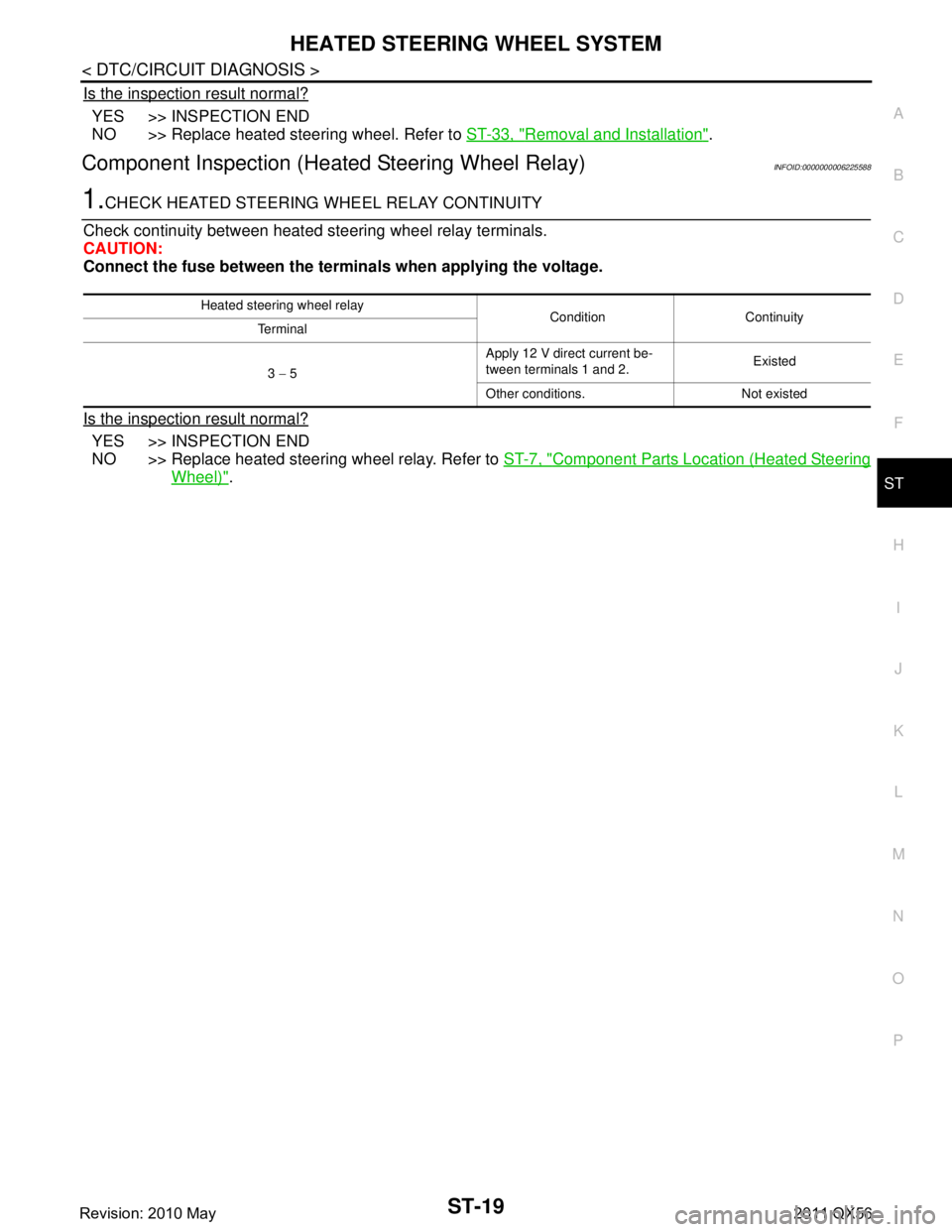
Is the inspection result normal?
YES >> INSPECTION END
NO >> Replace heated steering wheel. Refer to ST-33, "
Removal and Installation".
Component Inspection (Heated Steering Wheel Relay)INFOID:0000000006225588
1.CHECK HEATED STEERING WHEEL RELAY CONTINUITY
Check continuity between heated st eering wheel relay terminals.
CAUTION:
Connect the fuse between the termina ls when applying the voltage.
Is the inspection result normal?
YES >> INSPECTION END
NO >> Replace heated steering wheel relay. Refer to ST-7, "
Component Parts Location (Heated Steering
Wheel)".
Heated steering wheel relay
Condition Continuity
Te r m i n a l
3 − 5 Apply 12 V direct current be-
tween terminals 1 and 2.
Existed
Other conditions. Not existed
Revision: 2010 May2011 QX56
Page 5008 of 5598
HEATED STEERING WHEEL SWITCH INDICATOR LAMPST-21
< DTC/CIRCUIT DIAGNOSIS >
C
DE
F
H I
J
K L
M A
B
ST
N
O P
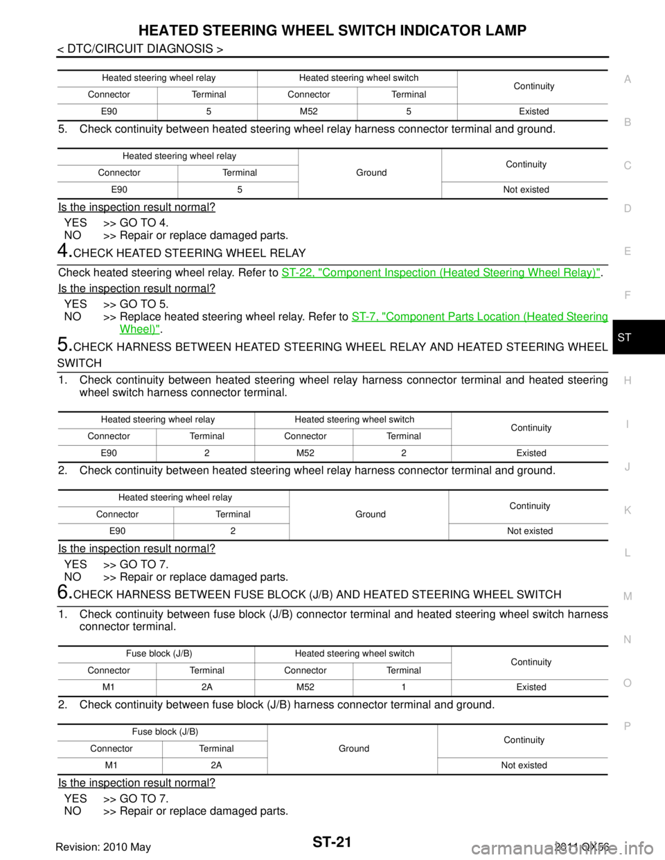
5. Check continuity between heated steering w heel relay harness connector terminal and ground.
Is the inspection result normal?
YES >> GO TO 4.
NO >> Repair or replace damaged parts.
4.CHECK HEATED STEERING WHEEL RELAY
Check heated steering wheel relay. Refer to ST-22, "
Component Inspection (Heated Steering Wheel Relay)".
Is the inspection result normal?
YES >> GO TO 5.
NO >> Replace heated steering wheel relay. Refer to ST-7, "
Component Parts Location (Heated Steering
Wheel)".
5.CHECK HARNESS BETWEEN HEATED STEERING WHEEL RELAY AND HEATED STEERING WHEEL
SWITCH
1. Check continuity between heated steering wheel relay harness connector terminal and heated steering
wheel switch harness connector terminal.
2. Check continuity between heated steering w heel relay harness connector terminal and ground.
Is the inspection result normal?
YES >> GO TO 7.
NO >> Repair or replace damaged parts.
6.CHECK HARNESS BETWEEN FUSE BLOCK (J/B) AND HEATED STEERING WHEEL SWITCH
1. Check continuity between fuse block (J/B) connec tor terminal and heated steering wheel switch harness
connector terminal.
2. Check continuity between fuse block (J/B) harness connector terminal and ground.
Is the inspection result normal?
YES >> GO TO 7.
NO >> Repair or replace damaged parts.
Heated steering wheel relay Heated steering wheel switch Continuity
Connector Terminal Connector Terminal
E90 5 M52 5 Existed
Heated steering wheel relay GroundContinuity
Connector Terminal
E90 5 Not existed
Heated steering wheel relay Heated steering wheel switch Continuity
Connector Terminal Connector Terminal
E90 2 M52 2 Existed
Heated steering wheel relay GroundContinuity
Connector Terminal
E90 2 Not existed
Fuse block (J/B) Heated steering wheel switch Continuity
Connector Terminal Connector Terminal
M1 2A M52 1 Existed
Fuse block (J/B) GroundContinuity
Connector Terminal
M1 2A Not existed
Revision: 2010 May2011 QX56
Page 5009 of 5598
ST-22
< DTC/CIRCUIT DIAGNOSIS >
HEATED STEERING WHEEL SWITCH INDICATOR LAMP
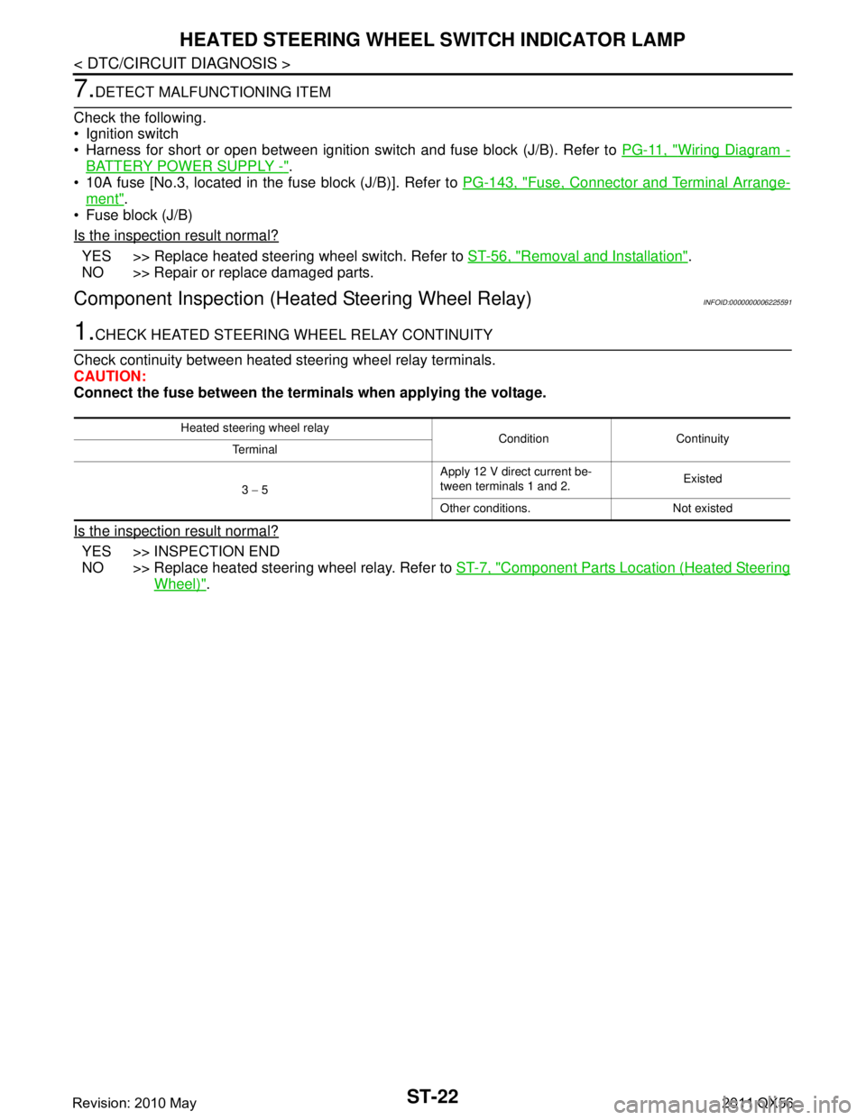
7.DETECT MALFUNCTIONING ITEM
Check the following.
Ignition switch
Harness for short or open between ignition switch and fuse block (J/B). Refer to PG-11, "
Wiring Diagram -
BATTERY POWER SUPPLY -".
10A fuse [No.3, located in the fuse block (J/B)]. Refer to PG-143, "
Fuse, Connector and Terminal Arrange-
ment".
Fuse block (J/B)
Is the inspection result normal?
YES >> Replace heated steering wheel switch. Refer to ST-56, "Removal and Installation".
NO >> Repair or replace damaged parts.
Component Inspection (H eated Steering Wheel Relay)INFOID:0000000006225591
1.CHECK HEATED STEERING WHEEL RELAY CONTINUITY
Check continuity between heated steering wheel relay terminals.
CAUTION:
Connect the fuse between the termi nals when applying the voltage.
Is the inspection result normal?
YES >> INSPECTION END
NO >> Replace heated steering wheel relay. Refer to ST-7, "
Component Parts Location (Heated Steering
Wheel)".
Heated steering wheel relay
Condition Continuity
Terminal
3 − 5 Apply 12 V direct current be-
tween terminals 1 and 2.
Existed
Other conditions. Not existed
Revision: 2010 May2011 QX56
Page 5011 of 5598
ST-24
< SYMPTOM DIAGNOSIS >
HEATED STEERING WHEEL SYSTEM DOES NOT ACTIVATE
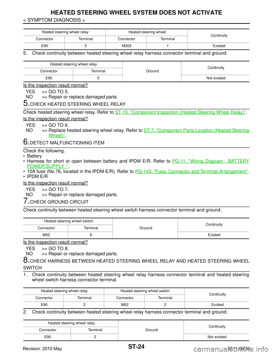
5. Check continuity between heated steering wheel relay harness connector terminal and ground.
Is the inspection result normal?
YES >> GO TO 5.
NO >> Repair or replace damaged parts.
5.CHECK HEATED STEERING WHEEL RELAY
Check heated steering wheel relay. Refer to ST-19, "
Component Inspection (Heated Steering Wheel Relay)".
Is the inspection result normal?
YES >> GO TO 6.
NO >> Replace heated steering wheel relay. Refer to ST-7, "
Component Parts Location (Heated Steering
Wheel)".
6.DETECT MALFUNCTIONING ITEM
Check the following.
Battery
Harness for short or open between bat tery and IPDM E/R. Refer to PG-11, "
Wiring Diagram - BATTERY
POWER SUPPLY -".
10A fuse (No.76, located in the IPDM E/R). Refer to PG-143, "
Fuse, Connector and Terminal Arrangement".
IPDM E/R
Is the inspection result normal?
YES >> GO TO 7.
NO >> Repair or replace damaged parts.
7.CHECK GROUND CIRCUIT
Check continuity between heated steering wheel switch harness connector terminal and ground.
Is the inspection result normal?
YES >> GO TO 8.
NO >> Repair or replace damaged parts.
8.CHECK HARNESS BETWEEN HEATED STEERING WHEEL RELAY AND HEATED STEERING WHEEL
SWITCH
1. Check continuity between heated steering wheel relay harness connector terminal and heated steering
wheel switch harness connector terminal.
2. Check continuity between heated steering w heel relay harness connector terminal and ground.
Heated steering wheel relay Heated steering wheel
Continuity
Connector Terminal Connector Terminal
E90 5 M303 1 Existed
Heated steering wheel relay GroundContinuity
Connector Terminal
E90 5 Not existed
Heated steering wheel switch GroundContinuity
Connector Terminal
M52 6 Existed
Heated steering wheel relay Heated steering wheel switch Continuity
Connector Terminal Connector Terminal
E90 2 M52 2 Existed
Heated steering wheel relay GroundContinuity
Connector Terminal
E90 2 Not existed
Revision: 2010 May2011 QX56