2011 INFINITI QX56 fuse
[x] Cancel search: fusePage 5012 of 5598
HEATED STEERING WHEEL SYSTEM DOES NOT ACTIVATE
ST-25
< SYMPTOM DIAGNOSIS >
C
D E
F
H I
J
K L
M A
B
ST
N
O P
Is the inspection result normal?
YES >> GO TO 9.
NO >> Repair or replace damaged parts.
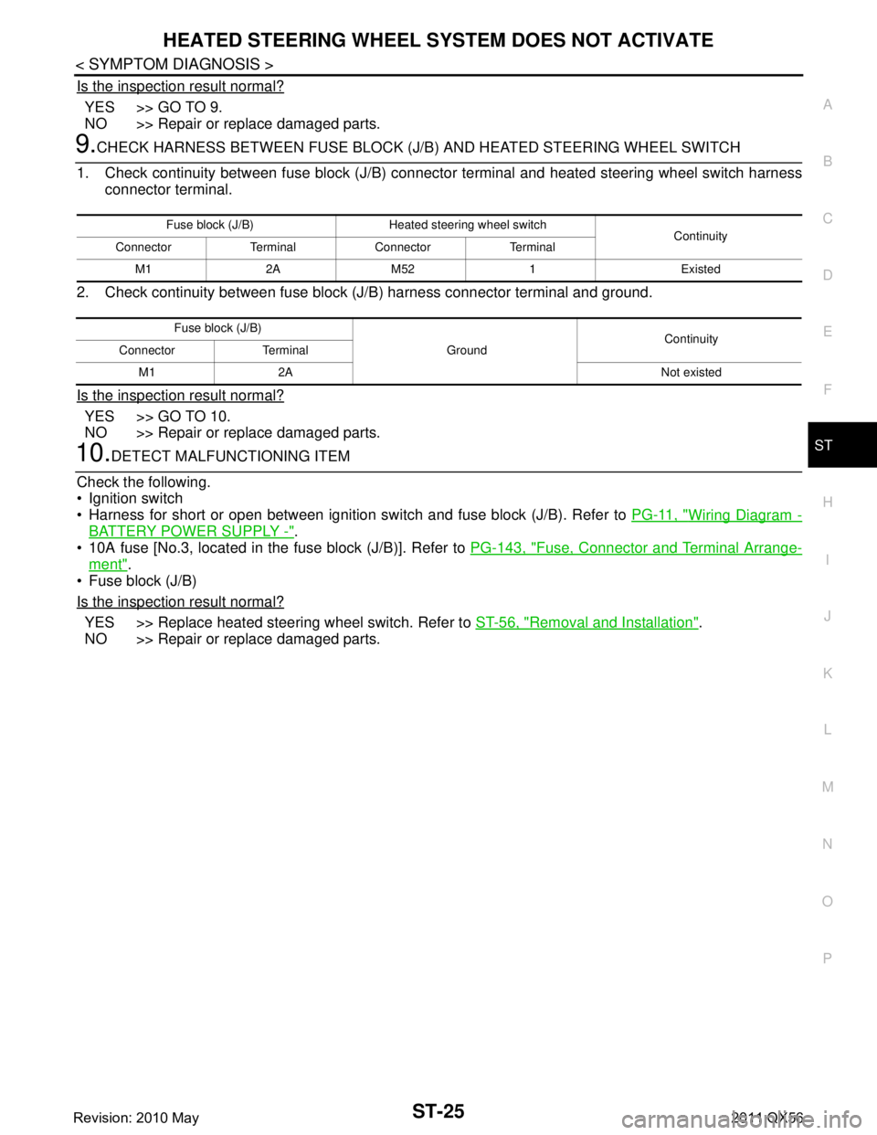
9.CHECK HARNESS BETWEEN FUSE BLOCK (J/B) AND HEATED STEERING WHEEL SWITCH
1. Check continuity between fuse block (J/B) connec tor terminal and heated steering wheel switch harness
connector terminal.
2. Check continuity between fuse block (J/B) harness connector terminal and ground.
Is the inspection result normal?
YES >> GO TO 10.
NO >> Repair or replace damaged parts.
10.DETECT MALFUNCTIONING ITEM
Check the following.
Ignition switch
Harness for short or open between ignition s witch and fuse block (J/B). Refer to PG-11, "
Wiring Diagram -
BATTERY POWER SUPPLY -".
10A fuse [No.3, located in the fuse block (J/B)]. Refer to PG-143, "
Fuse, Connector and Terminal Arrange-
ment".
Fuse block (J/B)
Is the inspection result normal?
YES >> Replace heated steering wheel switch. Refer to ST-56, "Removal and Installation".
NO >> Repair or replace damaged parts.
Fuse block (J/B) Heated steering wheel switch Continuity
Connector Terminal Connector Terminal
M1 2A M52 1 Existed
Fuse block (J/B) GroundContinuity
Connector Terminal
M1 2A Not existed
Revision: 2010 May2011 QX56
Page 5014 of 5598
HEATED STEERING WHEEL SWITCH INDICATOR LAMP DOES NOT TURN ON
ST-27
< SYMPTOM DIAGNOSIS >
C
D E
F
H I
J
K L
M A
B
ST
N
O P
Is the inspection result normal?
YES >> GO TO 4.
NO >> Repair or replace damaged parts.
4.CHECK HEATED STEERING WHEEL RELAY
Check heated steering wheel relay. Refer to ST-22, "
Component Inspection (Heated Steering Wheel Relay)".
Is the inspection result normal?
YES >> GO TO 5.
NO >> Replace heated steering wheel relay. Refer to ST-7, "
Component Parts Location (Heated Steering
Wheel)".
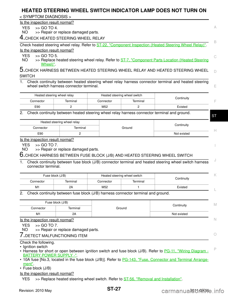
5.CHECK HARNESS BETWEEN HEATED STEERING WHEEL RELAY AND HEATED STEERING WHEEL
SWITCH
1. Check continuity between heated steering wheel relay harness connector terminal and heated steering
wheel switch harness connector terminal.
2. Check continuity between heated steering w heel relay harness connector terminal and ground.
Is the inspection result normal?
YES >> GO TO 7.
NO >> Repair or replace damaged parts.
6.CHECK HARNESS BETWEEN FUSE BLOCK (J/B) AND HEATED STEERING WHEEL SWITCH
1. Check continuity between fuse block (J/B) connec tor terminal and heated steering wheel switch harness
connector terminal.
2. Check continuity between fuse block (J/B) harness connector terminal and ground.
Is the inspection result normal?
YES >> GO TO 7.
NO >> Repair or replace damaged parts.
7.DETECT MALFUNCTIONING ITEM
Check the following.
Ignition switch
Harness for short or open between ignition s witch and fuse block (J/B). Refer to PG-11, "
Wiring Diagram -
BATTERY POWER SUPPLY -".
10A fuse [No.3, located in the fuse block (J/B)]. Refer to PG-143, "
Fuse, Connector and Terminal Arrange-
ment".
Fuse block (J/B)
Is the inspection result normal?
YES >> Replace heated steering wheel switch. Refer to ST-56, "Removal and Installation".
Heated steering wheel relay Heated steering wheel switch
Continuity
Connector Terminal Connector Terminal
E90 2 M52 2 Existed
Heated steering wheel relay GroundContinuity
Connector Terminal
E90 2 Not existed
Fuse block (J/B) Heated steering wheel switch Continuity
Connector Terminal Connector Terminal
M1 2A M52 1 Existed
Fuse block (J/B) GroundContinuity
Connector Terminal
M1 2A Not existed
Revision: 2010 May2011 QX56
Page 5017 of 5598
ST-30
< PERIODIC MAINTENANCE >
POWER STEERING FLUID
PERIODIC MAINTENANCE
POWER STEERING FLUID
InspectionINFOID:0000000006225597
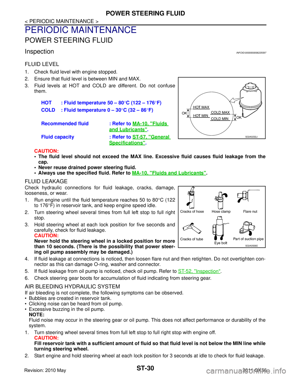
FLUID LEVEL
1. Check fluid level with engine stopped.
2. Ensure that fluid level is between MIN and MAX.
3. Fluid levels at HOT and COLD are different. Do not confuse
them.
CAUTION:
The fluid level should not exceed the MAX line. Excessive flui d causes fluid leakage from the
cap.
Never reuse drained power steering fluid.
Always use the specified fluid. Refer to MA-10, "
Fluids and Lubricants".
FLUID LEAKAGE
Check hydraulic connections for fluid leakage, cracks, damage,
looseness, or wear.
1. Run engine until the fluid temperature reaches 50 to 80 °C (122
to 176 °F) in reservoir tank, and keep engine speed idle.
2. Turn steering wheel several times from full left stop to full right stop.
3. Hold steering wheel at each lock position for five seconds and carefully, check for fluid leakage.
CAUTION:
Never hold the steering wheel in a locked position for more
than 10 seconds. (There is the possibility that power steer-
ing oil pump assembly may be damaged.)
4. If fluid leakage at connections is noticed, then loos en flare nut and then retighten. Do not overtighten con-
nector as this can damage O-ring, washer and connector.
5. If fluid leakage from oil pump is noticed, check oil pump. Refer to ST-52, "
Inspection".
6. Check steering gear boots for accumulation of fluid indicating from steering gear.
AIR BLEEDING HYDRAULIC SYSTEM
If air bleeding is not complete, the following symptoms can be observed.
Bubbles are created in reservoir tank.
Clicking noise can be heard from oil pump.
Excessive buzzing in the oil pump. NOTE:
Fluid noise may occur in the steering gear or oil pump. This does not affect performance or durability of the
system.
1. Turn steering wheel several times from full left stop to full right stop with engine off. CAUTION:
Fill reservoir tank with a sufficien t amount of fluid so that fluid level is not below the MIN line while
turning steering wheel.
2. Start engine and hold steering wheel at each lock position for 3 seconds at idle to check for fluid leakage.
HOT : Fluid temperature 50 – 80
°C (122 – 176 °F)
COLD : Fluid temperature 0 – 30 °C (32 – 86 °F)
Recommended fluid : Refer to MA-10, "
Fluids
and Lubricants".
Fluid capacity : Refer to ST-57, "
General
Specifications".
SGIA0232J
SGIA0506E
Revision: 2010 May2011 QX56
Page 5038 of 5598
POWER STEERING OIL PUMPST-51
< REMOVAL AND INSTALLATION >
C
DE
F
H I
J
K L
M A
B
ST
N
O P
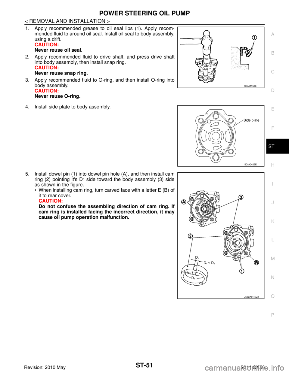
1. Apply recommended grease to oil seal lips (1). Apply recom- mended fluid to around oil seal. Install oil seal to body assembly,
using a drift.
CAUTION:
Never reuse oil seal.
2. Apply recommended fluid to drive shaft, and press drive shaft into body assembly, then install snap ring.
CAUTION:
Never reuse snap ring.
3. Apply recommended fluid to O-ring, and then install O-ring into body assembly.
CAUTION:
Never reuse O-ring.
4. Install side plate to body assembly.
5. Install dowel pin (1) into dowel pin hole (A), and then install cam ring (2) pointing it's D
1 side toward the body assembly (3) side
as shown in the figure.
When installing cam ring, turn carved face with a letter E (B) of
it to rear cover.
CAUTION:
Do not confuse the assembling direction of cam ring. If
cam ring is installed facing th e incorrect direction, it may
cause oil pump operation malfunction.
SGIA1150E
SGIA0422E
JSGIA0110ZZ
Revision: 2010 May2011 QX56
Page 5059 of 5598
STC-14
< DTC/CIRCUIT DIAGNOSIS >
POWER SUPPLY AND GROUND CIRCUIT
DTC/CIRCUIT DIAGNOSIS
POWER SUPPLY AND GROUND CIRCUIT
Diagnosis ProcedureINFOID:0000000006256125
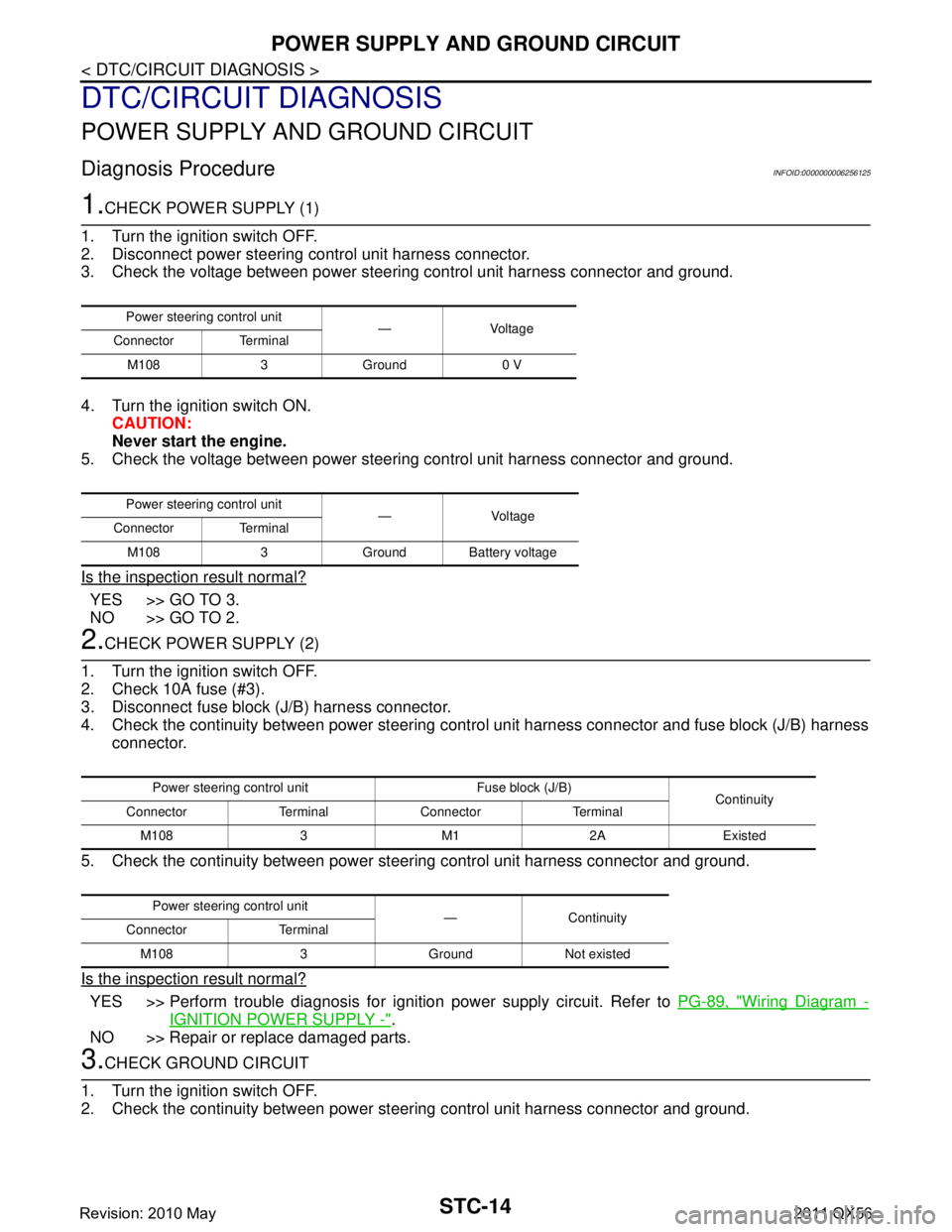
1.CHECK POWER SUPPLY (1)
1. Turn the ignition switch OFF.
2. Disconnect power steering control unit harness connector.
3. Check the voltage between power steering control unit harness connector and ground.
4. Turn the ignition switch ON. CAUTION:
Never start the engine.
5. Check the voltage between power steering control unit harness connector and ground.
Is the inspection result normal?
YES >> GO TO 3.
NO >> GO TO 2.
2.CHECK POWER SUPPLY (2)
1. Turn the ignition switch OFF.
2. Check 10A fuse (#3).
3. Disconnect fuse block (J/B) harness connector.
4. Check the continuity between power steering cont rol unit harness connector and fuse block (J/B) harness
connector.
5. Check the continuity between power st eering control unit harness connector and ground.
Is the inspection result normal?
YES >> Perform trouble diagnosis for ignition power supply circuit. Refer to PG-89, "Wiring Diagram -
IGNITION POWER SUPPLY -".
NO >> Repair or replace damaged parts.
3.CHECK GROUND CIRCUIT
1. Turn the ignition switch OFF.
2. Check the continuity between power st eering control unit harness connector and ground.
Power steering control unit
—Voltage
Connector Terminal
M108 3 Ground 0 V
Power steering control unit — Voltage
Connector Terminal
M108 3 Ground Battery voltage
Power steering control unit Fuse block (J/B) Continuity
Connector Terminal Connector Terminal
M108 3 M1 2A Existed
Power steering control unit —Continuity
Connector Terminal
M108 3 Ground Not existed
Revision: 2010 May2011 QX56
Page 5082 of 5598
STR-14
< DTC/CIRCUIT DIAGNOSIS >
B TERMINAL CIRCUIT
DTC/CIRCUIT DIAGNOSIS
B TERMINAL CIRCUIT
Diagnosis ProcedureINFOID:0000000006275524
CAUTION:
Perform diagnosis under the condition that engine cannot start by the following procedure.
1. Remove fuel pump fuse.
2. Crank or start the engine (where possi ble) until the fuel pressure is released.
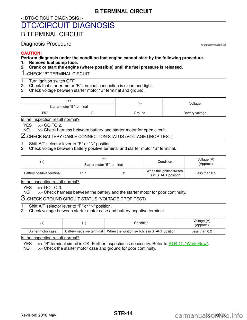
1.CHECK “B” TERMINAL CIRCUIT
1. Turn ignition switch OFF.
2. Check that starter motor “B” terminal connection is clean and tight.
3. Check voltage between starter motor “B” terminal and ground.
Is the inspection result normal?
YES >> GO TO 2.
NO >> Check harness between battery and starter motor for open circuit.
2.CHECK BATTERY CABLE CONNECTION STATUS (VOLTAGE DROP TEST)
1. Shift A/T selector lever to “P” or “N” position.
2. Check voltage between battery positive terminal and starter motor “B” terminal.
Is the inspection result normal?
YES >> GO TO 3.
NO >> Check harness between the battery and the starter motor for poor continuity.
3.CHECK GROUND CIRCUIT STATUS (VOLTAGE DROP TEST)
1. Shift A/T selector lever to “P” or “N” position.
2. Check voltage between starter motor case and battery negative terminal.
Is the inspection result normal?
YES >> “B” terminal circuit is OK. Further inspection is necessary. Refer to STR-11, "Work Flow".
NO >> Check the starter motor case and ground for poor continuity.
(+) (–) Voltage
Starter motor “B” terminal
F57 2 Ground Battery voltage
(+) (–)
ConditionVoltage (V)
(Approx.)
Starter motor “B” terminal
Battery positive terminal F57 2 When the ignition switch
is in START position Less than 0.5
(+) (–) Condition Voltage (V)
(Approx.)
Starter motor case Battery negative terminal When the ignition switch is in START position Less than 0.2
Revision: 2010 May2011 QX56
Page 5083 of 5598
S CONNECTOR CIRCUITSTR-15
< DTC/CIRCUIT DIAGNOSIS >
C
DE
F
G H
I
J
K L
M A
STR
NP
O
S CONNECTOR CIRCUIT
Diagnosis ProcedureINFOID:0000000006275525
CAUTION:
Perform diagnosis under the cond
ition that engine cannot start by the following procedure.
1. Remove fuel pump fuse.
2. Crank or start the engine (where possi ble) until the fuel pressure is released.
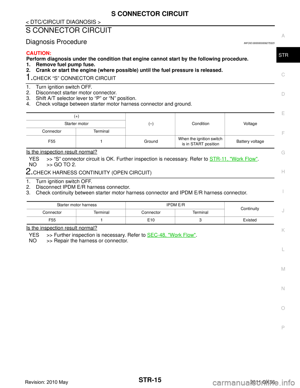
1.CHECK “S” CONNECTOR CIRCUIT
1. Turn ignition switch OFF.
2. Disconnect starter motor connector.
3. Shift A/T selector lever to “P” or “N” position.
4. Check voltage between starter motor harness connector and ground.
Is the inspection result normal?
YES >> “S” connector circuit is OK. Furt her inspection is necessary. Refer to STR-11, "Work Flow".
NO >> GO TO 2.
2.CHECK HARNESS CONTI NUITY (OPEN CIRCUIT)
1. Turn ignition switch OFF.
2. Disconnect IPDM E/R harness connector.
3. Check continuity between starter motor harness connector and IPDM E/R harness connector.
Is the inspection result normal?
YES >> Further inspection is necessary. Refer to SEC-48, "Work Flow".
NO >> Repair the harness or connector.
(+)
(–) Condition Voltage
Starter motor
Connector Terminal
F55 1 Ground When the ignition switch
is in START position Battery voltage
Starter motor harness IPDM E/R
Continuity
Connector Terminal Connector Terminal
F55 1 E10 3 Existed
Revision: 2010 May2011 QX56
Page 5144 of 5598
![INFINITI QX56 2011 Factory Service Manual
TM-56
< SYSTEM DESCRIPTION >[7AT: RE7R01B]
SYSTEM
Input/Output Signal Chart
*: This signal is transmitted via CAN communication line.
The TCM receives the manual mode signal, non-manual mode signal INFINITI QX56 2011 Factory Service Manual
TM-56
< SYSTEM DESCRIPTION >[7AT: RE7R01B]
SYSTEM
Input/Output Signal Chart
*: This signal is transmitted via CAN communication line.
The TCM receives the manual mode signal, non-manual mode signal](/manual-img/42/57033/w960_57033-5143.png)
TM-56
< SYSTEM DESCRIPTION >[7AT: RE7R01B]
SYSTEM
Input/Output Signal Chart
*: This signal is transmitted via CAN communication line.
The TCM receives the manual mode signal, non-manual mode signal, manual mode shift up signal and
manual mode shift down signal from combination meter via CAN communication line. The TCM shifts shift
pattern control to the manual mode based on these signal s, and then shifts the A/T by operating each sole-
noid valve according to the shift operation of the driver.
The TCM prohibits the manual mode while being in fail-safe mode due to an A/T malfunction, etc. Refer to TM-74, "
Fail-Safe".
Manual Mode Information
The TCM transmits the manual mode shift refusal signal to the combination meter if the TCM refuses the
transmission from the driving status of vehicle when the selector lever shifts to “UP (+ side)” or “DOWN (−
side)” side. The combination meter blinks shift indicator on the combination meter and sounds the buzzer to
indicate the driver that the shifting is not performed when receiving this signal. However, the TCM does not
transmit the manual mode shift refusal signal in the conditions as per the following.
- When the selector lever shifts to “DOWN ( − side)” side in 1GR.
- When the selector lever shifts to “UP (+ side)” side in 7GR.
LOCK-UP CONTROL
LOCK-UP CONTROL : System DiagramINFOID:0000000006226777
LOCK-UP CONTROL : System DescriptionINFOID:0000000006226778
The torque converter clutch piston in the torque conv erter is engaged to eliminate torque converter slip to
increase power transmission efficiency.
Lock-up operation, however, is prohibited when A/T fluid temperature is too low.
The torque converter clutch control valve operation is controlled by the torque converter clutch solenoid
valve, which is controlled by a signal from TCM, and the torque converter clutch control valve engages or
releases the torque converter clutch piston.
Item Signal TCM function Actuator
Output speed sensor Vehicle speed
Manual mode High and low reverse clutch
solenoid valve
Direct clutch solenoid valve
Input clutch solenoid valve
Low brake solenoid valve
2346 brake solenoid valve
Front brake solenoid valve
Torque converter clutch sole- noid valve
Line pressure solenoid valve
Anti-interlock solenoid valve
A/T fluid temperature sensor ATF temperature
ECM
Engine speed signal*
Accelerator pedal position sig-
nal*
Combination meter Manual mode signal*
Non-manual mode signal*
Manual mode shift up signal*
Manual mode shift down signal*
JSDIA1350GB
Revision: 2010 May2011 QX56