Page 4062 of 5598
PG
IPDM E/R (INTELLIGENT POWER DISTRIBUTION MODULE ENGINE ROOM)
PG-143
< WIRING DIAGRAM >
C
D E
F
G H
I
J
K L
B A
O P
N
IPDM E/R (INTELLIGENT POWER
DISTRIBUTION MODULE ENGINE
ROOM)
Fuse, Connector and Terminal ArrangementINFOID:0000000006275755
JCMWM7722GB
Revision: 2010 May2011 QX56
Page 4081 of 5598
PG-162
< BASIC INSPECTION >
FUSE INSPECTION
FUSE INSPECTION
How To CheckINFOID:0000000006275774
If fuse is blown, be sure to eliminate cause of malfunction beforeinstalling new fuse.
Use fuse of specified rating. Never use fuse of more than specified
rating.
Do not partially install fuse; always insert it into fuse holder prop- erly.
Remove fuse for “ELECTRICAL PARTS (BAT)” if vehicle is not used for a long period of time.
CEL083
Revision: 2010 May2011 QX56
Page 4118 of 5598

SYSTEM INITIALIZATIONPWC-33
< BASIC INSPECTION >
C
DE
F
G H
I
J
L
M A
B
PWC
N
O P
SYSTEM INITIALIZATION
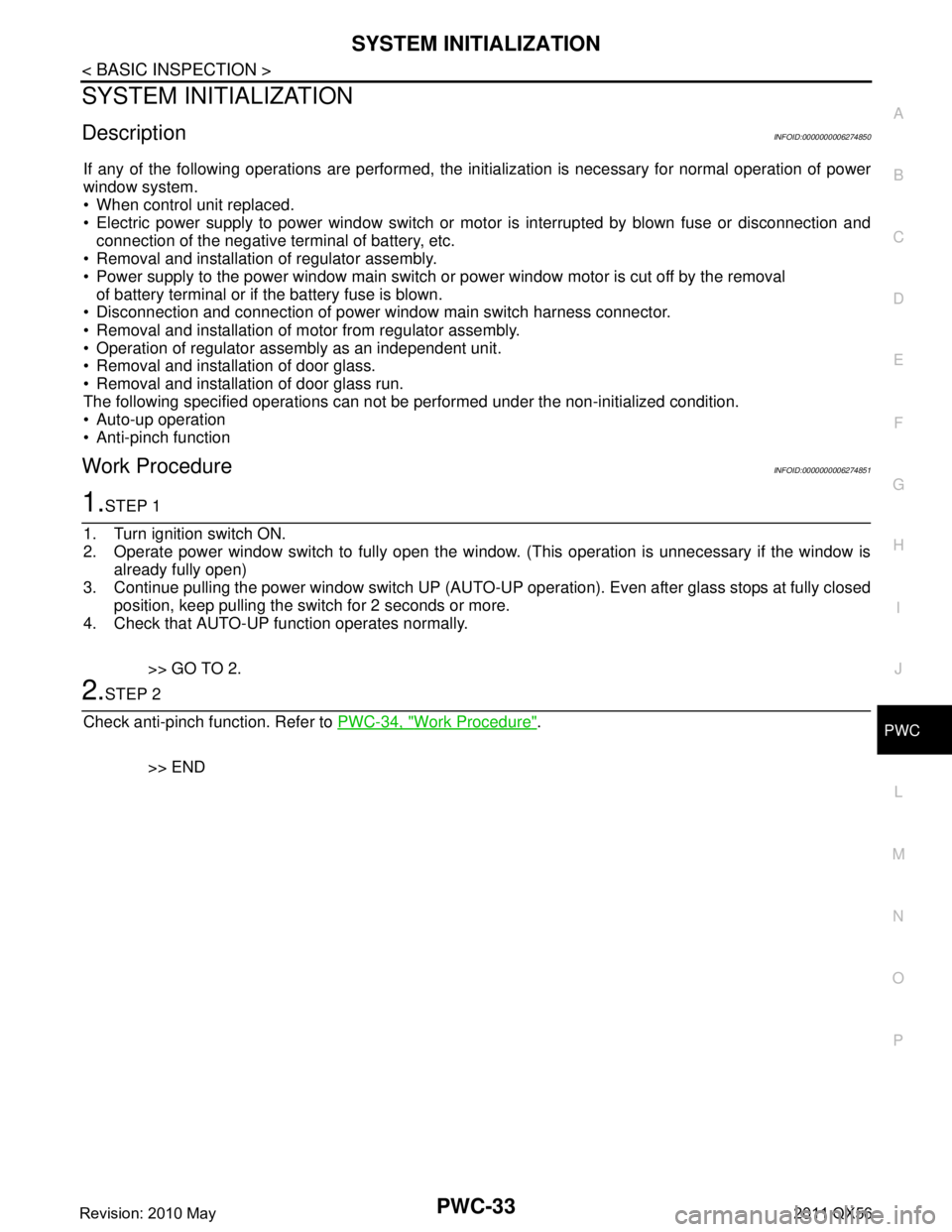
DescriptionINFOID:0000000006274850
If any of the following operations are performed, the in itialization is necessary for normal operation of power
window system.
When control unit replaced.
Electric power supply to power window switch or motor is interrupted by blown fuse or disconnection and
connection of the negative terminal of battery, etc.
Removal and installation of regulator assembly.
Power supply to the power window main switch or power window motor is cut off by the removal
of battery terminal or if the battery fuse is blown.
Disconnection and connection of power window main switch harness connector.
Removal and installation of motor from regulator assembly.
Operation of regulator assembly as an independent unit.
Removal and installation of door glass.
Removal and installation of door glass run.
The following specified operations can not be performed under the non-initialized condition.
Auto-up operation
Anti-pinch function
Work ProcedureINFOID:0000000006274851
1.STEP 1
1. Turn ignition switch ON.
2. Operate power window switch to fully open the wi ndow. (This operation is unnecessary if the window is
already fully open)
3. Continue pulling the power window switch UP (AUTO-UP operation). Even after glass stops at fully closed
position, keep pulling the switch for 2 seconds or more.
4. Check that AUTO-UP function operates normally.
>> GO TO 2.
2.STEP 2
Check anti-pinch function. Refer to PWC-34, "
Work Procedure".
>> END
Revision: 2010 May2011 QX56
Page 4119 of 5598

PWC-34
< BASIC INSPECTION >
CHECK ANTI-PINCH FUNCTION
CHECK ANTI-PINCH FUNCTION
DescriptionINFOID:0000000006274852
If any of the following operations are performed, the initialization is necessary for normal operation of anti-
pinch function.
When control unit replaced.
Electric power supply to power window switch or mo tor is interrupted by blown fuse or disconnection and
connection of the negative terminal of battery, etc.
Removal and installation of regulator assembly.
Power supply to the power window main switch or power window motor is cut off by the removal
of battery terminal or if the battery fuse is blown.
Disconnection and connection of power window main switch harness connector.
Removal and installation of motor from regulator assembly.
Operation of regulator assembly as an independent unit.
Removal and installation of door glass.
Removal and installation of door glass run.
The following specified operations can not be performed under the non-initialized condition.
Auto-up operation
Anti-pinch function
Work ProcedureINFOID:0000000006274853
1.CHECK ANTI-PINCH FUNCTION
Fully open the door window.
Place a piece of wood near fully closed position.
Close door glass completely with AUTO-UP.
Check the following conditions
- Check that glass lowers for approximately 150 mm (5.9 in) without pinching piece of wood and stops.
- Check that glass does not rise not when operating the power window main switch while lowering. CAUTION:
Perform initial setting when AUTO-UP operation or anti-pinch function does not operate normally.
Check that AUTO-UP operates before inspectio n when system initialization is performed.
Do not check with hands and other body parts b ecause they may be pinched. Do not get pinched.
>> END
Revision: 2010 May2011 QX56
Page 4182 of 5598
![INFINITI QX56 2011 Factory Service Manual
PWO
POWER SUPPLY AND GROUND CIRCUITPWO-23
< DTC/CIRCUIT DIAGNOSIS > [AC 120 V OUTLET]
C
D
E
F
G H
I
J
K L
B A
O P
N
DTC/CIRCUIT DIAGNOSIS
POWER SUPPLY AND GROUND CIRCUIT
Diagnosis ProcedureINFOID:000 INFINITI QX56 2011 Factory Service Manual
PWO
POWER SUPPLY AND GROUND CIRCUITPWO-23
< DTC/CIRCUIT DIAGNOSIS > [AC 120 V OUTLET]
C
D
E
F
G H
I
J
K L
B A
O P
N
DTC/CIRCUIT DIAGNOSIS
POWER SUPPLY AND GROUND CIRCUIT
Diagnosis ProcedureINFOID:000](/manual-img/42/57033/w960_57033-4181.png)
PWO
POWER SUPPLY AND GROUND CIRCUITPWO-23
< DTC/CIRCUIT DIAGNOSIS > [AC 120 V OUTLET]
C
D
E
F
G H
I
J
K L
B A
O P
N
DTC/CIRCUIT DIAGNOSIS
POWER SUPPLY AND GROUND CIRCUIT
Diagnosis ProcedureINFOID:0000000006257089
1.CHECK FUSE
Check that the following fuse is not blown.
Is the fuse fusing?
YES >> Replace the blown fuse after repairing the affected circuit if a fuse is blown.
NO >> GO TO 2.
2.CHECK INVERTER UNIT POWER SUPPLY CIRCUIT
Check voltage between inverter unit harness connector and ground.
Is the inspection result normal?
YES >> GO TO 3.
NO >> Repair or replace the inverter unit power supply circuit.
3.CHECK INVERTER UNIT GROUND CIRCUIT
1. Turn the ignition switch OFF.
2. Disconnect the inverter unit connector.
3. Check for continuity between inverter unit harness connector and ground.
Is the inspection result normal?
YES >> INSPECTION END
NO >> Repair or replace the inverter unit ground circuit.
Signal name Fuse No.
Battery power supply 79
Te r m i n a l Condition
Vo l ta g e
(Approx.)
(+) (–)
Inverter unit GroundIgnition switch
Connector Terminal
M143 4 OFF Battery voltage
Inverter unit GroundContinuity
Connector Terminal
M143 8 Existed
Revision: 2010 May2011 QX56
Page 4183 of 5598
PWO-24
< DTC/CIRCUIT DIAGNOSIS >[AC 120 V OUTLET]
AC 120 V OUTLET MAIN SWITCH POWER SUPPLY CIRCUIT
AC 120 V OUTLET MAIN SWITCH
POWER SUPPLY CIRCUIT
Diagnosis ProcedureINFOID:0000000006257095
1.CHECK FUSE
Check that the following fuse is not blown.
Is the fuse fusing?
YES >> Replace the blown fuse after repairing the affected circuit if a fuse is blown.
NO >> GO TO 2.
2.CHECK POWER SUPPLY FOR AC 120 V OUTLET MAIN SWITCH
1. Turn ignition switch ON.
2. Check for voltage between the AC 120 V main switch harness connector and ground.
Is the inspection result normal?
YES >> INSPECTION END
NO >> Repair the AC 120 V main switch power supply circuit.
Signal name Fuse No.
Ignition power supply 3
Te r m i n a l s Condition
Vo l ta g e
(Approx.)
(+) (–)
AC 120 V outlet main switch
GroundIgnition switch
Connector Terminal
M144 1 OFF 0 V
ON 12 V
Revision: 2010 May2011 QX56
Page 4338 of 5598

B2454 SEAT BLT PWR DR CIRCSBC-41
< DTC/CIRCUIT DIAGNOSIS >
C
DE
F
G
I
J
K L
M A
B
SBC
N
O P
B2454 SEAT BLT PWR DR CIRC
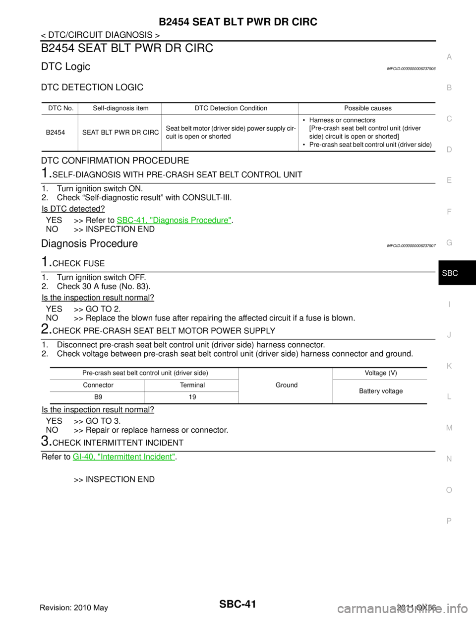
DTC LogicINFOID:0000000006237906
DTC DETECTION LOGIC
DTC CONFIRMATION PROCEDURE
1.SELF-DIAGNOSIS WITH PRE-CRASH SEAT BELT CONTROL UNIT
1. Turn ignition switch ON.
2. Check “Self-diagnostic result” with CONSULT-III.
Is DTC detected?
YES >> Refer to SBC-41, "Diagnosis Procedure".
NO >> INSPECTION END
Diagnosis ProcedureINFOID:0000000006237907
1.CHECK FUSE
1. Turn ignition switch OFF.
2. Check 30 A fuse (No. 83).
Is the inspection result normal?
YES >> GO TO 2.
NO >> Replace the blown fuse after repairing the affected circuit if a fuse is blown.
2.CHECK PRE-CRASH SEAT BELT MOTOR POWER SUPPLY
1. Disconnect pre-crash seat belt control unit (driver side) harness connector.
2. Check voltage between pre-crash seat belt control unit (driver side) harness connector and ground.
Is the inspection result normal?
YES >> GO TO 3.
NO >> Repair or replace harness or connector.
3.CHECK INTERMITTENT INCIDENT
Refer to GI-40, "
Intermittent Incident".
>> INSPECTION END
DTC No. Self-diagnosis item DTC De tection Condition Possible causes
B2454 SEAT BLT PWR DR CIRC Seat belt motor (driver
side) power supply cir-
cuit is open or shorted Harness or connectors
[Pre-crash seat belt control unit (driver
side) circuit is open or shorted]
Pre-crash seat belt co ntrol unit (driver side)
Pre-crash seat belt control unit (driver side)
GroundVoltage (V)
Connector Terminal Battery voltage
B9 19
Revision: 2010 May2011 QX56
Page 4340 of 5598

B2456 SEAT BLT PWR ASSBC-43
< DTC/CIRCUIT DIAGNOSIS >
C
DE
F
G
I
J
K L
M A
B
SBC
N
O P
B2456 SEAT BLT PWR AS
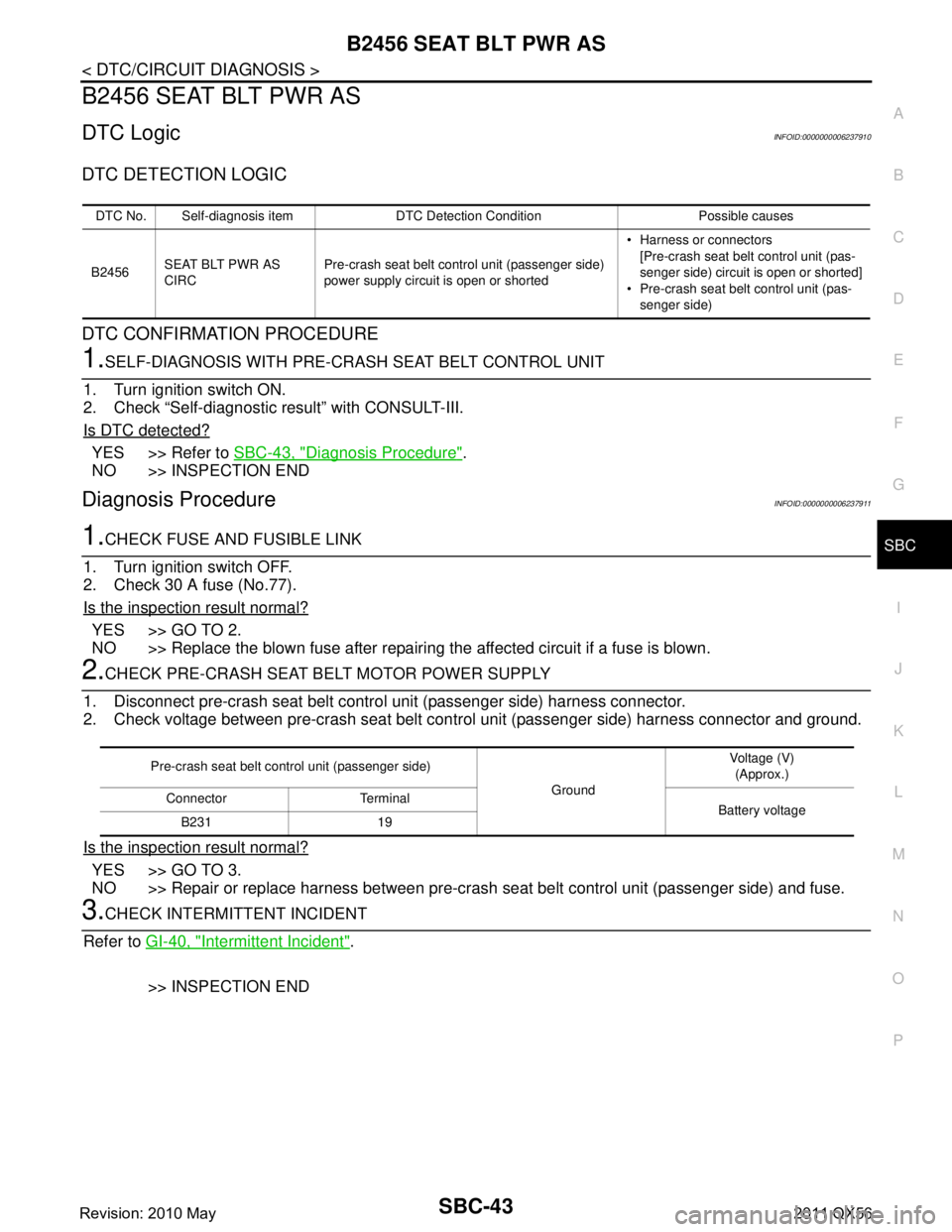
DTC LogicINFOID:0000000006237910
DTC DETECTION LOGIC
DTC CONFIRMATION PROCEDURE
1.SELF-DIAGNOSIS WITH PRE-CRASH SEAT BELT CONTROL UNIT
1. Turn ignition switch ON.
2. Check “Self-diagnostic result” with CONSULT-III.
Is DTC detected?
YES >> Refer to SBC-43, "Diagnosis Procedure".
NO >> INSPECTION END
Diagnosis ProcedureINFOID:0000000006237911
1.CHECK FUSE AND FUSIBLE LINK
1. Turn ignition switch OFF.
2. Check 30 A fuse (No.77).
Is the inspection result normal?
YES >> GO TO 2.
NO >> Replace the blown fuse after repairing the affected circuit if a fuse is blown.
2.CHECK PRE-CRASH SEAT BELT MOTOR POWER SUPPLY
1. Disconnect pre-crash seat belt contro l unit (passenger side) harness connector.
2. Check voltage between pre-crash seat belt cont rol unit (passenger side) harness connector and ground.
Is the inspection result normal?
YES >> GO TO 3.
NO >> Repair or replace harness between pre-crash seat belt control unit (passenger side) and fuse.
3.CHECK INTERMITTENT INCIDENT
Refer to GI-40, "
Intermittent Incident".
>> INSPECTION END
DTC No. Self-diagnosis item DTC Detection Condition Possible causes
B2456 SEAT BLT PWR AS
CIRC Pre-crash seat belt control unit (passenger side)
power supply circuit is open or shorted Harness or connectors
[Pre-crash seat belt control unit (pas-
senger side) circuit is open or shorted]
Pre-crash seat belt control unit (pas-
senger side)
Pre-crash seat belt control unit (passenger side)
GroundVoltage (V)
(Approx.)
Connector Terminal Battery voltage
B231 19
Revision: 2010 May2011 QX56