2011 INFINITI QX56 brake sensor
[x] Cancel search: brake sensorPage 3745 of 5598

MWI-2
DIAGNOSIS SYSTEM (COMBINATION
METER) ..............................................................
29
On Board Diagnosis Function .............................. ...29
CONSULT-III Function ...........................................30
ECU DIAGNOSIS INFORMATION ..............35
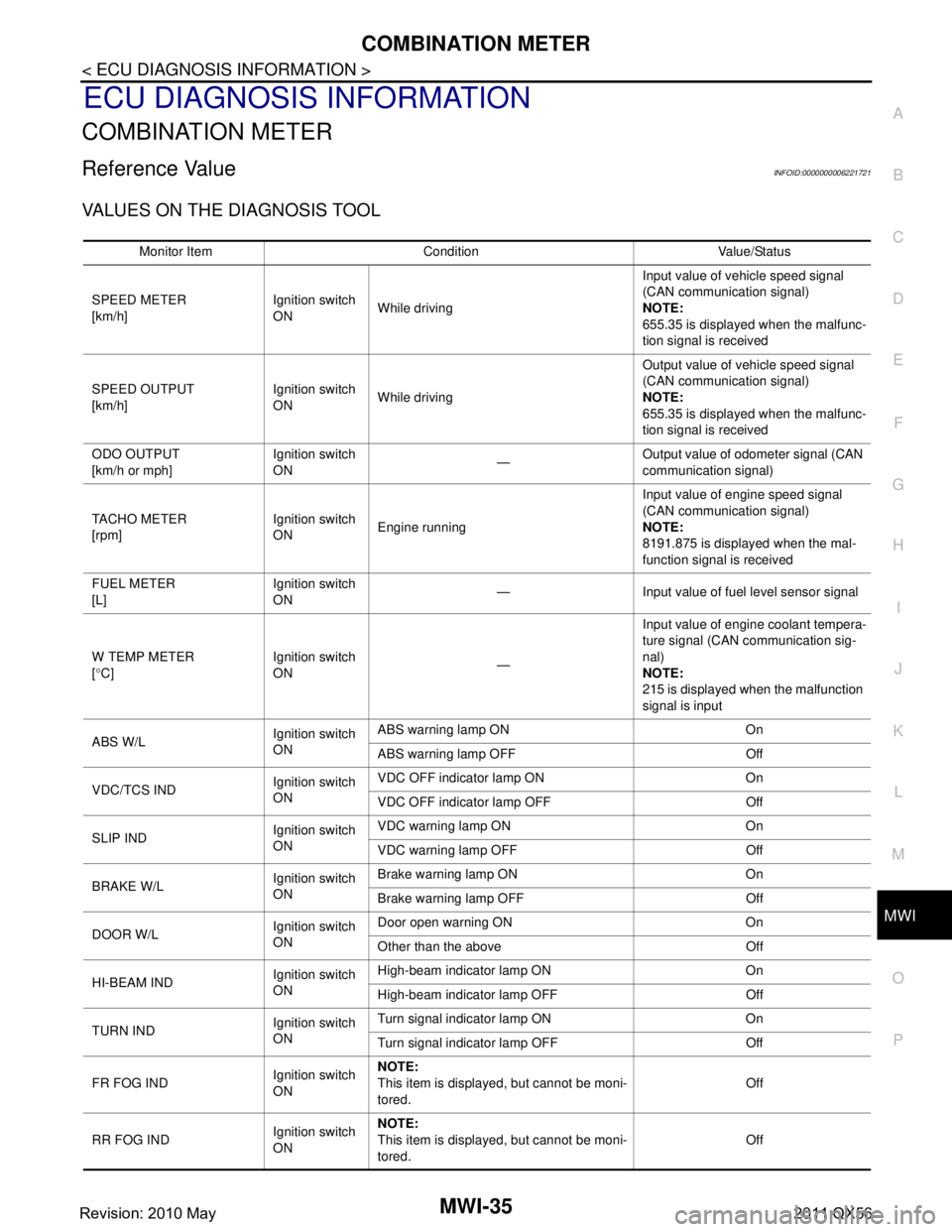
COMBINATION METER ................................. ...35
Reference Value .................................................. ...35
Fail-Safe .................................................................42
DTC Index ..............................................................43
IPDM E/R ...........................................................44
List of ECU Reference ......................................... ...44
WIRING DIAGRAM .....................................45
METER SYSTEM ............................................ ...45
Wiring Diagram .................................................... ...45
CLOCK ...............................................................55
Wiring Diagram .................................................... ...55
BASIC INSPECTION ...................................57
DIAGNOSIS AND REPAIR WORKFLOW
(METER SYSTEM ) .......................................... ...
57
Work flow ............................................................. ...57
DTC/CIRCUIT DIAGNOSIS ...................... ...59
U1000 CAN COMM CIRCUIT ......................... ...59
Description ........................................................... ...59
DTC Logic ...............................................................59
Diagnosis Procedure .............................................59
U1010 CONTROL UNIT (CAN) .........................60
Description ........................................................... ...60
DTC Logic ...............................................................60
Diagnosis Procedure ..............................................60
B2205 VEHICLE SPEED ...................................61
Description ........................................................... ...61
DTC Logic ...............................................................61
Diagnosis Procedure .............................................61
B2267 ENGINE SPEED .....................................62
Description ........................................................... ...62
DTC Logic ...............................................................62
Diagnosis Procedure ..............................................62
B2268 WATER TEMP ........................................63
Description ........................................................... ...63
DTC Logic ...............................................................63
Diagnosis Procedure ..............................................63
POWER SUPPLY AND GROUND CIRCUIT .....64
COMBINATION METER ........................................ ...64
COMBINATION METER : Diagnosis Procedure ....64
TRIP RESET AND ILLUMINATION CON-
TROL SWITCH SIGNAL CIRCUIT ....................
65
Diagnosis Procedure ............................................ ...65
Component Inspection ............................................66
TRIP COMPUTER SWITCH SIGNAL CIRCUIT
...
67
Diagnosis Procedure ............................................ ...67
Component Inspection ............................................68
FUEL LEVEL SENSOR SIGNAL CIRCUIT .......69
Component Function Check ................................ ...69
Diagnosis Procedure ..............................................69
Component Inspection ............................................70
OIL PRESSURE SWITCH SIGNAL CIRCUIT ...71
Component Function Check ...................................71
Diagnosis Procedure ...............................................71
Component Inspection ............................................71
WASHER LEVEL SWITCH SIGNAL CIRCUIT ...73
Diagnosis Procedure ............................................ ...73
Component Inspection ............................................73
A/C AUTO AMP. CONNECTION RECOGNI-
TION SIGNAL CIRCUIT ....................................
74
Diagnosis Procedure ........................................... ...74
SYMPTOM DIAGNOSIS ............................75
THE FUEL GAUGE INDICATOR DOES NOT
OPERATE ....................................................... ...
75
Description ........................................................... ...75
Diagnosis Procedure ...............................................75
THE TRIP RESET AND ILLUMINATION CON-
TROL SWITCH IS INOPERATIVE ....................
76
Description ........................................................... ...76
Diagnosis Procedure ...............................................76
THE TRIP COMPUTER SWITCH IS INOPER-
ATIVE .................................................................
77
Description ........................................................... ...77
Diagnosis Procedure ...............................................77
THE OIL PRESSURE WARNING LAMP
DOES NOT TURN ON .................................... ...
78
Description ........................................................... ...78
Diagnosis Procedure ...............................................78
THE OIL PRESSURE WARNING LAMP
DOES NOT TURN OFF .................................. ...
79
Description ........................................................... ...79
Diagnosis Procedure ...............................................79
THE PARKING BRAKE RELEASE WARNING
CONTINUES DISPLAYING, OR DOES NOT
DISPLAY ............................................................
80
Description ........................................................... ...80
Diagnosis Procedure ...............................................80
Revision: 2010 May2011 QX56
Page 3749 of 5598
MWI-6
< SYSTEM DESCRIPTION >
COMPONENT PARTS
SYSTEM DESCRIPTION
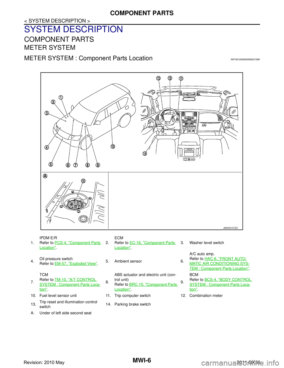
COMPONENT PARTS
METER SYSTEM
METER SYSTEM : Component Parts LocationINFOID:0000000006221690
1.IPDM E/R
Refer to
PCS-4, "Component Parts
Location". 2.
ECM
Refer to
EC-16, "
Component Parts
Location". 3. Washer level switch
4. Oil pressure switch
Refer to
EM-57, "
Exploded View".5. Ambient sensor 6. A/C auto amp.
Refer to
HAC-6, "
FRONT AUTO-
MATIC AIR CONDITIONING SYS-
TEM : Component Parts Location".
7. TCM
Refer to
TM-10, "
A/T CONTROL
SYSTEM : Componen t Parts Loca-
tion". 8.ABS actuator and electric unit (con-
trol unit)
Refer to
BRC-10, "
Component Parts
Location". 9.BCM
Refer to
BCS-4, "
BODY CONTROL
SYSTEM : Component Parts Loca-
tion".
10. Fuel level sensor unit 11. Trip computer switch 12. Combination meter
13. Trip reset and illumination control
switch 14. Parking brake switch
A. Under of left side second seat
JSNIA3157ZZ
Revision: 2010 May2011 QX56
Page 3750 of 5598

MWI
COMPONENT PARTSMWI-7
< SYSTEM DESCRIPTION >
C
DE
F
G H
I
J
K L
M B A
O P
METER SYSTEM : Com ponent DescriptionINFOID:0000000006221691
CLOCK
Unit Description
Combination meter Controls the following with the signals received from each unit via CAN communication and the sig-
nals from switches and sensors.
Speedometer
Tachometer
Engine coolant temperature gauge
Fuel gauge
Engine oil pressure gauge
Voltmeter
Warning lamps
Indicator lamps
Meter illumination control
Meter effect function
Information display
Trip computer switch Transmits the following signals to the combination meter.
Enter switch signal
Select switch signal
Trip reset and illumination con-
trol switch Transmits the following signals to the combination meter.
Trip reset switch signal
Illumination control switch signal (+)
Illumination control switch signal (
−)
ECM Transmits the following signals to the combination meter via CAN communication.
Engine speed signal
Engine coolant temperature signal
Engine status signal
Fuel consumption monitor signal
ABS actuator and electric unit
(control unit) Transmits the vehicle speed signal to the combination meter via CAN communication.
IPDM E/R Transmits the oil pressure switch signal to the BCM via CAN communication.
BCM Transmits the following signals to the combination meter via CAN communication.
Oil pressure switch signal
Position light request signal
Dimmer signal
Door switch signal
Meter ring illumination request signal
Starter relay status signal
TCM Transmits the shift position signal to the combination meter via CAN communication.
A/T shift selector Transmits the following signals to the combination meter.
Manual mode signal
Non-manual mode signal
Manual mode shift up signal
Manual mode shift down signal
Fuel level sensor unit Transmits the fuel level sensor signal to the combination meter.
Oil pressure switch Transmits the oil pressure switch signal to the IPDM E/R.
Ambient sensor Transmits the ambient sensor signal to the combination meter.
A/C auto amp. Transmits the A/C auto amp. connection recognition signal to the combination meter.
Parking brake switch Transmits the parking brake switch signal to the combination meter.
Washer level switch Transmits the washer level switch signal to the combination meter.
Revision: 2010 May2011 QX56
Page 3756 of 5598
MWI
SYSTEMMWI-13
< SYSTEM DESCRIPTION >
C
DE
F
G H
I
J
K L
M B A
O P
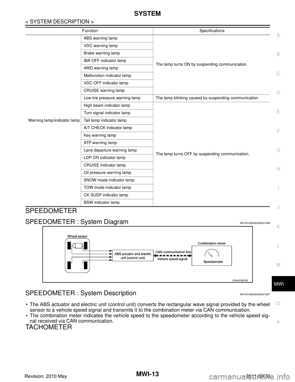
SPEEDOMETER
SPEEDOMETER : System DiagramINFOID:0000000006221696
SPEEDOMETER : System DescriptionINFOID:0000000006221697
The ABS actuator and electric unit (control unit) conv erts the rectangular wave signal provided by the wheel
sensor to a vehicle speed signal and transmits it to the combination meter via CAN communication.
The combination meter indicates the vehicle speed to the speedometer according to the vehicle speed sig-
nal received via CAN communication.
TACHOMETER
Warning lamp/indicator lamp ABS warning lamp
The lamp turns ON by suspending communication.
VDC warning lamp
Brake warning lamp
IBA OFF indicator lamp
4WD warning lamp
Malfunction indicator lamp
VDC OFF indicator lamp
CRUISE warning lamp
Low tire pressure warning lamp The lamp blinking caused by suspending communication.
High beam indicator lamp
The lamp turns OFF by suspending communication.
Turn signal indicator lamp
Tail lamp indicator lamp
A/T CHECK indicator lamp
Key warning lamp
AT P w a r n i n g l a m p
Lane departure warning lamp
LDP ON indicator lamp
CRUISE indicator lamp
Oil pressure warning lamp
SNOW mode indicator lamp
TOW mode indicator lamp
CK SUSP indicator lamp
BSW indicator lamp
Function Specifications
JSNIA2382GB
Revision: 2010 May2011 QX56
Page 3766 of 5598
MWI
SYSTEMMWI-23
< SYSTEM DESCRIPTION >
C
DE
F
G H
I
J
K L
M B A
O P
The ambient sensor input value that is displayed on “Data Monitor” of CONSULT-III is the value before the
correction. It may not match the indica ted temperature on the information display.
After removal and installation of the battery and comb ination meter, an ambient sensor-detected tempera-
ture is indicated on the information display.
Depending on engine heat or heat on the road surfaces, an ambient temperature may be indicated higher
than actual one.
INTERRUPT INDICATION
The combination meter displays an interrupt regarding a warning, alert, and maintenance on the information
display, based on signals received from each unit and switch.
When conditions are satisfied, the normal screen swit ches to a warning screen to display an interrupt.
Door Open Warning
When all the following operating conditions are satisfied, the combination meter displays a door open warn-
ing on the information display by an interrupt.
The combination meter judges showing/hiding of “door open warning”, according to the signals below:
Parking Brake Release Warning
When all the following operating conditions are satisfi ed, the combination meter displays a parking brake
release warning on the information display by an interrupt.
The combination meter judges showing/hiding of “parki ng brake release warning”, according to the signals
below:
Low Fuel Warning
When all the following operating conditions are satisfied, the combination meter displays a low fuel warning on the information display by an interrupt.
*: With the vehicle in a horizontal position
The combination meter judges showing/hiding of “low fuel warning”, according to the signals below:
Operating condition
Ignition switch ON
Door Any door is open
Signal name Signal path
Ignition signal —
Door switch signal Door switch BCM Combination meter
Operating condition
Ignition switch ON
Parking brake Applied
Vehicle speed 7 km/h (4.3 MPH) or more
Signal name Signal path
Ignition signal —
Parking brake switch signal Parking brake switch Combination meter
Vehicle speed signal ABS actuator and electric unit (control unit) Combination meter
Operating condition
Ignition switch ON
Fuel remaining quantity
*Approximately 15.4 (4 US gal, 3-3/8 Imp gal) or less (including fuel remained)
Revision: 2010 May2011 QX56
Page 3776 of 5598
MWI
DIAGNOSIS SYSTEM (COMBINATION METER)
MWI-33
< SYSTEM DESCRIPTION >
C
D E
F
G H
I
J
K L
M B A
O P
*: DDS (hill descent control) NOTE:
Some items are not available according to vehicle specification.
SPECIAL FUNCTION
Special menu
W/L ON HISTORY
Stores histories when warning/indicator lamp is turned on.
“W/L ON HISTORY” indicates the “TIME” when the warning/ indicator lamp is turned on.
The “TIME” above is:
- 0: The condition that the warning/indicator lamp has been turned on 1 or more times after starting the engine and waiting for 30 seconds.
- 1 - 39: The number of times the engine was restarted after the 0 condition.
- NO W/L ON HISTORY: Stores NO (0) turning on history of warning/indicator lamp.
NOTE:
W/L ON HISTORY is not stored for approximately 30 seconds after the engine starts.
Brake warning lamp does not store any history when the parking brake is applied or the brake fluid level gets
low.
Display Item
AT SFT DWN SW
[On/Off] Status of manual mode shift down switch.
PKB SW
[On/Off] Status of parking brake switch.
BUCKLE SW
[On/Off] Status of seat belt buckle switch (driver side).
BRAKE OIL SW
[On/Off] Status of brake fluid level switch.
A/C AMP CONN
[Off] This item is displayed, but cannot be monitored.
ENTER SW
[On/Off] Status of (ENTER) switch.
SELECT SW
[On/Off] Status of (SELECT) switch.
DISTANCE
[km] Value of distance to empty calculated by combination meter.
OUTSIDE TEMP
[ ° C or °F] Ambient temperature value converted from ambient sensor signal received from
ambient sensor.
NOTE:
This may not match with the temperature value indicated on the information dis-
play. (Because the information display value is a corrected value from the ambient
sensor input value.)
FUEL LOW SIG
[On/Off] Status of fuel level low warning signal to output to AV control unit via CAN com-
munication.
TOW MODE IND
[On/Off] Status of TOW mode indicator lamp judged from TOW mode indicator lamp signal
received from TCM with CAN communication line.
BUZZER
[On/Off] XBuzzer status (in the combination meter) is detected from the buzzer output signal
received from each unit via CAN communication and the warning output condition
of the combination meter.
Display item [Unit]
MAIN
SIGNALS Description
Display item Description
W/L ON HISTORY Lighting history of warning lamp and indicator lamp can be checked.
Revision: 2010 May2011 QX56
Page 3778 of 5598
MWI
COMBINATION METERMWI-35
< ECU DIAGNOSIS INFORMATION >
C
DE
F
G H
I
J
K L
M B A
O P
ECU DIAGNOSIS INFORMATION
COMBINATION METER
Reference ValueINFOID:0000000006221721
VALUES ON THE DIAGNOSIS TOOL
Monitor Item Condition Value/Status
SPEED METER
[km/h] Ignition switch
ON
While driving Input value of vehicle speed signal
(CAN communication signal)
NOTE:
655.35 is displayed when the malfunc-
tion signal is received
SPEED OUTPUT
[km/h] Ignition switch
ON
While driving Output value of vehicle speed signal
(CAN communication signal)
NOTE:
655.35 is displayed when the malfunc-
tion signal is received
ODO OUTPUT
[km/h or mph] Ignition switch
ON
—Output value of odometer signal (CAN
communication signal)
TACHO METER
[rpm] Ignition switch
ON
Engine running Input value of engine speed signal
(CAN communication signal)
NOTE:
8191.875 is displayed when the mal-
function signal is received
FUEL METER
[L] Ignition switch
ON
— Input value of fuel level sensor signal
W TEMP METER
[ ° C] Ignition switch
ON
—Input value of engine coolant tempera-
ture signal (CAN communication sig-
nal)
NOTE:
215 is displayed when the malfunction
signal is input
ABS W/L Ignition switch
ONABS warning lamp ON On
ABS warning lamp OFF Off
VDC/TCS IND Ignition switch
ONVDC OFF indicator lamp ON On
VDC OFF indicator lamp OFF Off
SLIP IND Ignition switch
ONVDC warning lamp ON On
VDC warning lamp OFF Off
BRAKE W/L Ignition switch
ONBrake warning lamp ON On
Brake warning lamp OFF Off
DOOR W/L Ignition switch
ONDoor open warning ON On
Other than the above Off
HI-BEAM IND Ignition switch
ONHigh-beam indicator lamp ON On
High-beam indicator lamp OFF Off
TURN IND Ignition switch
ONTurn signal indicator lamp ON On
Turn signal indicator lamp OFF Off
FR FOG IND Ignition switch
ONNOTE:
This item is displayed, but cannot be moni-
tored.
Off
RR FOG IND Ignition switch
ONNOTE:
This item is displayed, but cannot be moni-
tored.
Off
Revision: 2010 May2011 QX56
Page 3783 of 5598
MWI-40
< ECU DIAGNOSIS INFORMATION >
COMBINATION METER
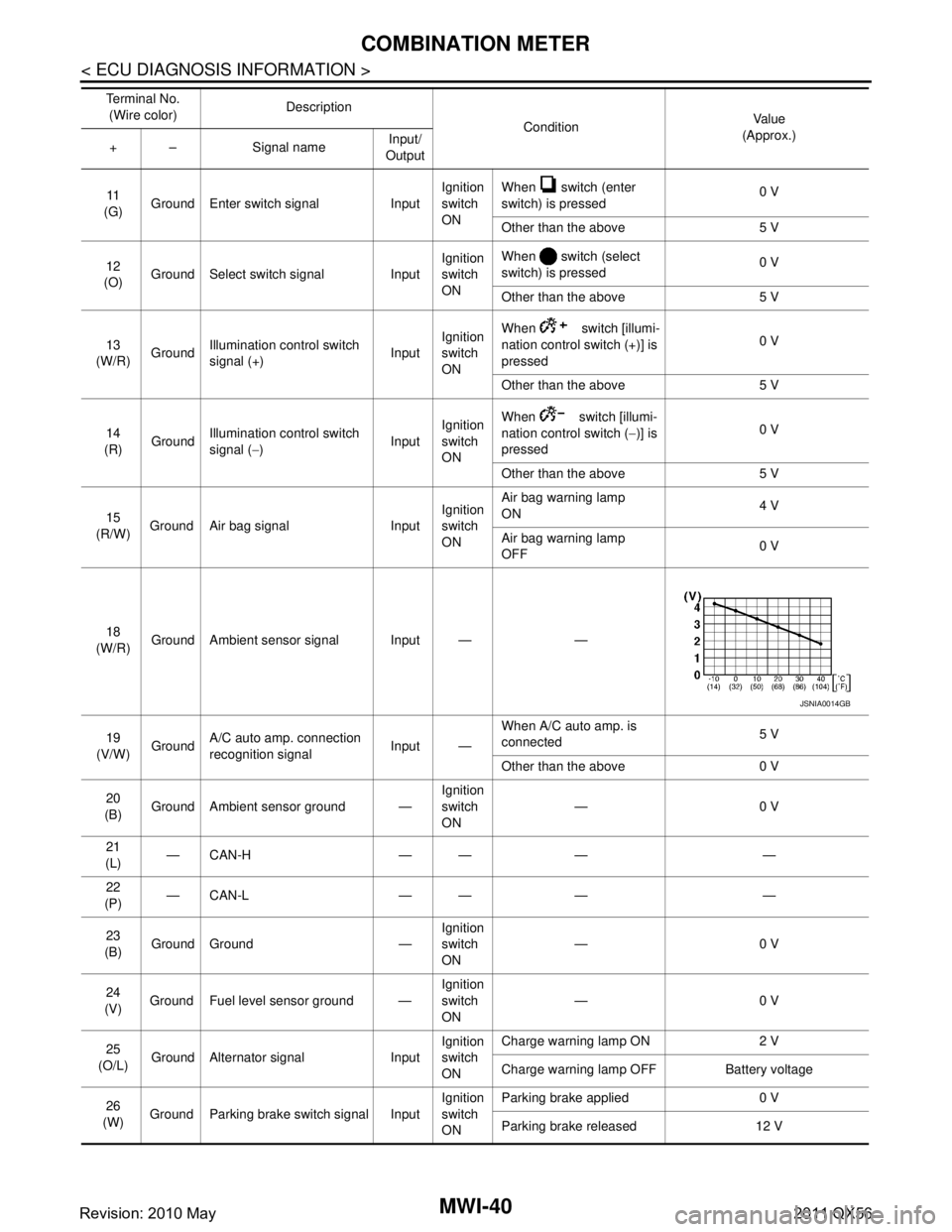
11
(G) Ground Enter switch signal Input Ignition
switch
ONWhen switch (enter
switch) is pressed
0 V
Other than the above 5 V
12
(O) Ground Select switch signal Input Ignition
switch
ONWhen switch (select
switch) is pressed
0 V
Other than the above 5 V
13
(W/R) Ground
Illumination control switch
signal (+) InputIgnition
switch
ON When switch [illumi-
nation control sw
itch (+)] is
pressed 0 V
Other than the above 5 V
14
(R) Ground Illumination control switch
signal (
−) InputIgnition
switch
ON When switch [illumi-
nation control switch (
−)] is
pressed 0 V
Other than the above 5 V
15
(R/W) Ground Air bag signal Input Ignition
switch
ONAir bag warning lamp
ON
4 V
Air bag warning lamp
OFF 0 V
18
(W/R) Ground Ambient sensor signal Input — —
19
(V/W) Ground A/C auto amp. connection
recognition signal Input —When A/C auto amp. is
connected
5 V
Other than the above 0 V
20
(B) Ground Ambient sensor ground — Ignition
switch
ON—0 V
21
(L) —CAN-H — — — —
22
(P) —CAN-L — — — —
23
(B) Ground Ground — Ignition
switch
ON
—0 V
24
(V) Ground Fuel level sensor ground — Ignition
switch
ON—0 V
25
(O/L) Ground Alternator signal Input Ignition
switch
ONCharge warning lamp ON 2 V
Charge warning lamp OFF Battery voltage
26
(W) Ground Parking brake switch signal Input Ignition
switch
ONParking brake applied 0 V
Parking brake released 12 V
Te r m i n a l N o .
(Wire color) Description
ConditionVa l u e
(Approx.)
+ – Signal name Input/
Output
JSNIA0014GB
Revision: 2010 May2011 QX56