2011 INFINITI QX56 brake sensor
[x] Cancel search: brake sensorPage 2172 of 5598
![INFINITI QX56 2011 Factory Service Manual
EC-148
< BASIC INSPECTION >[VK56VD]
IDLE AIR VOLUME LEARNING
IDLE AIR VOLUME LEARNING
DescriptionINFOID:0000000006217750
Idle Air Volume Learning is a function of ECM to learn
the idle air volume th INFINITI QX56 2011 Factory Service Manual
EC-148
< BASIC INSPECTION >[VK56VD]
IDLE AIR VOLUME LEARNING
IDLE AIR VOLUME LEARNING
DescriptionINFOID:0000000006217750
Idle Air Volume Learning is a function of ECM to learn
the idle air volume th](/manual-img/42/57033/w960_57033-2171.png)
EC-148
< BASIC INSPECTION >[VK56VD]
IDLE AIR VOLUME LEARNING
IDLE AIR VOLUME LEARNING
DescriptionINFOID:0000000006217750
Idle Air Volume Learning is a function of ECM to learn
the idle air volume that keeps engine idle speed within
the specific range. It must be perfo rmed under the following conditions:
Each time the electric throttle control actuator or ECM is replaced.
Idle speed or ignition timing is out of the specification.
Work ProcedureINFOID:0000000006217751
1.PRECONDITIONING
Check that all of the following conditions are satisfied.
Learning will be cancelled if any of the follo wing conditions are missed for even a moment.
Battery voltage: More than 12.9 V (At idle)
Engine coolant temperature: 70 - 105 °C (158 - 221 °F)
Selector lever position: P or N
Electric load switch: OFF
(Air conditioner, headlamp, rear window defogger)
On vehicles equipped with daytime light systems, if the parking brake is applied before the engine is
started the headlamp will not illuminate.
Steering wheel: Neutral (Straight-ahead position)
Vehicle speed: Stopped
Transmission: Warmed-up
- With CONSULT-III: Drive vehicle until “ATF TEMP 2” in “DATA MONITOR” mode of “A/T” system indicates
less than 0.9 V.
- Without CONSULT-III: Drive vehicle for 10 minutes.
Will CONSULT-III be used?
YES >> GO TO 2.
NO >> GO TO 3.
2.PERFORM IDLE AIR VOLUME LEARNING
WITH CONSULT-III
1. Perform Accelerator Pedal Released Position Learning. Refer to EC-146, "
Work Procedure".
2. Perform Throttle Valve Closed Position Learning. EC-147, "
Work Procedure".
3. Start engine and warm it up to normal operating temperature.
4. Select “IDLE AIR VOL LEARN” in “WORK SUPPORT” mode.
5. Touch “START” and wait 20 seconds.
Is
“CMPLT” displayed on CONSULT-III screen?
YES >> GO TO 4.
NO >> GO TO 5.
3.PERFORM IDLE AIR VOLUME LEARNING
WITHOUT CONSULT-III
NOTE:
It is better to count the ti me accurately with a clock.
It is impossible to switch the di agnostic mode when an accelerator pedal position sensor circuit has
a malfunction.
1. Perform Accelerator Pedal Released Position Learning. Refer to EC-146, "
Work Procedure".
2. Perform Throttle Valve Closed Position Learning. EC-147, "
Work Procedure".
3. Start engine and warm it up to normal operating temperature.
4. Turn ignition switch OFF and wait at least 10 seconds.
5. Confirm that accelerator pedal is fully releas ed, turn ignition switch ON and wait 3 seconds.
6. Repeat the following procedure quickly 5 times within 5 seconds.
- Fully depress the accelerator pedal.
- Fully release the accelerator pedal.
7. Wait 7 seconds, fully depress the accelerator pedal for approx. 20 seconds until the MIL stops blinking
and turns ON.
8. Fully release the accelerator pedal within 3 seconds after the MIL turns ON.
Revision: 2010 May2011 QX56
Page 2253 of 5598
![INFINITI QX56 2011 Factory Service Manual
P0130, P0150 A/F SENSOR 1EC-229
< DTC/CIRCUIT DIAGNOSIS > [VK56VD]
C
D
E
F
G H
I
J
K L
M A
EC
NP
O
If “TESTING” is not displayed after 20 seconds, retry from step 2.
CAUTION:
Always drive vehicle INFINITI QX56 2011 Factory Service Manual
P0130, P0150 A/F SENSOR 1EC-229
< DTC/CIRCUIT DIAGNOSIS > [VK56VD]
C
D
E
F
G H
I
J
K L
M A
EC
NP
O
If “TESTING” is not displayed after 20 seconds, retry from step 2.
CAUTION:
Always drive vehicle](/manual-img/42/57033/w960_57033-2252.png)
P0130, P0150 A/F SENSOR 1EC-229
< DTC/CIRCUIT DIAGNOSIS > [VK56VD]
C
D
E
F
G H
I
J
K L
M A
EC
NP
O
If “TESTING” is not displayed after 20 seconds, retry from step 2.
CAUTION:
Always drive vehicle at a safe speed.
Is
“TESTING” displayed on CONSULT-III screen?
YES >> GO TO 5.
NO >> Check A/F sensor 1 function again. GO TO 3.
5.PERFORM DTC CONFIRMATION PR OCEDURE FOR MALFUNCTION B-II
Release accelerator pedal fully.
NOTE:
Never apply brake when releasing the accelerator pedal.
Which does
“TESTING” change to?
COMPLETED>>GO TO 6.
OUT OF CONDITION>>Retry DTC CO NFIRMATION PROCEDURE. GO TO 4.
6.PERFORM DTC CONFIRMATION PROCEDURE FOR MALFUNCTION B-III
Touch “SELF-DIAG RESULT”.
Which is displayed on CONSULT-III screen?
YES >> INSPECTION END
NO >> Go to EC-230, "
Diagnosis Procedure".
7.PERFORM COMPONENT FUNCTION CHECK FOR MALFUNCTION B
WITH GST
Perform component function check. Refer to EC-229, "
Component Function Check".
NOTE:
Use component function check to check the overall function of the A/F sensor 1 circuit. During this check, a
1st trip DTC might not be confirmed.
Is the inspection result normal?
YES >> INSPECTION END
NO >> Go to EC-230, "
Diagnosis Procedure".
Component Function CheckINFOID:0000000006217805
1.PERFORM COMPONENT FUNCTION CHECK
WITH GST
1. Start engine and warm it up to normal operating temperature.
2. Drive the vehicle at a speed of 80 km/h (50 MPH) for a few minutes in the suitable gear position.
3. Shift the selector lever position to D, then rel ease the accelerator pedal fully until the vehicle speed
decreases to 50 km/h (31 MPH).
CAUTION:
Always drive vehicle at a safe speed.
NOTE:
Never apply brake when releasing the accelerator pedal.
4. Repeat steps 2 and 3 for 5 times.
5. Stop the vehicle and turn ignition switch OFF.
6. Wait at least 10 seconds and turn ignition switch ON.
7. Turn ignition switch OFF and wait at least 10 seconds.
8. Restart engine.
9. Repeat steps 2 and 3 for 5 times.
10. Stop the vehicle.
11. Check 1st trip DTC.
ENG SPEED 1,750 - 3,200 rpm
VHCL SPEED SE More than 64 km/h (40 mph)
B/FUEL SCHDL 1.0 - 8.0 msec
Selector lever D position
Revision: 2010 May2011 QX56
Page 2908 of 5598
![INFINITI QX56 2011 Factory Service Manual
FAX-8
< REMOVAL AND INSTALLATION >[2WD]
FRONT WHEEL HUB AND KNUCKLE
REMOVAL AND INSTALLATION
FRONT WHEEL HUB AND KNUCKLE
Exploded ViewINFOID:0000000006225418
Removal and InstallationINFOID:0000000006 INFINITI QX56 2011 Factory Service Manual
FAX-8
< REMOVAL AND INSTALLATION >[2WD]
FRONT WHEEL HUB AND KNUCKLE
REMOVAL AND INSTALLATION
FRONT WHEEL HUB AND KNUCKLE
Exploded ViewINFOID:0000000006225418
Removal and InstallationINFOID:0000000006](/manual-img/42/57033/w960_57033-2907.png)
FAX-8
< REMOVAL AND INSTALLATION >[2WD]
FRONT WHEEL HUB AND KNUCKLE
REMOVAL AND INSTALLATION
FRONT WHEEL HUB AND KNUCKLE
Exploded ViewINFOID:0000000006225418
Removal and InstallationINFOID:0000000006225419
REMOVAL
1. Remove tires with power tool. Refer to
WT-64, "Removal and Installation".
2. Remove brake hose bracket. Refer to BR-23, "
FRONT : Removal and Installation".
3. Remove caliper assembly mounting bolts. Hang caliper assembly in a place where it will not interfere with work. Refer to BR-37, "
BRAKE CALIPER ASSEMBLY : Removal and Installation".
CAUTION:
Never depress brake pedal while brake caliper is removed.
4. Remove disc rotor. CAUTION:
Put matching marks on the wh eel hub and bearing assembly and the disc rotor before removing
the disc rotor.
Never drop disc rotor.
5. Remove wheel sensor harness. Refer to BRC-134, "
FRONT WHEEL SENSOR : Removal and Installa-
tion".
CAUTION:
Never pull on wheel sensor harness.
6. Remove steering outer socket. Refer to ST-42, "
Removal and Installation".
7. Set suitable jack under lower link.
1. Steering knuckle 2. Cotter pin 3. Splash guard
4. Hub bolt 5. Wheel hub and bearing assembly 6. Disc rotor
Refer to GI-4, "
Components" for symbols in the figure.
JPDIF0294GB
Revision: 2010 May2011 QX56
Page 2918 of 5598
![INFINITI QX56 2011 Factory Service Manual
FAX-18
< REMOVAL AND INSTALLATION >[4WD]
FRONT WHEEL HUB AND KNUCKLE
REMOVAL AND INSTALLATION
FRONT WHEEL HUB AND KNUCKLE
Exploded ViewINFOID:0000000006225396
Removal and InstallationINFOID:000000000 INFINITI QX56 2011 Factory Service Manual
FAX-18
< REMOVAL AND INSTALLATION >[4WD]
FRONT WHEEL HUB AND KNUCKLE
REMOVAL AND INSTALLATION
FRONT WHEEL HUB AND KNUCKLE
Exploded ViewINFOID:0000000006225396
Removal and InstallationINFOID:000000000](/manual-img/42/57033/w960_57033-2917.png)
FAX-18
< REMOVAL AND INSTALLATION >[4WD]
FRONT WHEEL HUB AND KNUCKLE
REMOVAL AND INSTALLATION
FRONT WHEEL HUB AND KNUCKLE
Exploded ViewINFOID:0000000006225396
Removal and InstallationINFOID:0000000006225397
REMOVAL
1. Remove tires.
2. Remove brake hose bracket. Refer to
BR-23, "
FRONT : Removal and Installation".
3. Remove caliper assembly mounting bolts. Hang caliper assembly in a place where it will not interfere with work. Refer to BR-37, "
BRAKE CALIPER ASSEMBLY : Removal and Installation".
CAUTION:
Never depress brake pedal while brake caliper is removed.
4. Remove disc rotor. CAUTION:
Put matching marks on the wh eel hub and bearing assembly and the disc rotor before removing
the disc rotor.
Never drop disc rotor.
5. Remove wheel sensor harness. Refer to BRC-134, "
FRONT WHEEL SENSOR : Removal and Installa-
tion".
CAUTION:
Never pull on wheel sensor harness.
6. Remove steering outer socket. Refer to ST-42, "
Removal and Installation".
1. Steering knuckle 2. Cotter pin 3. Splash guard
4. Hub bolt 5. Wheel hub and bearing assembly 6. Disc rotor
7. Wheel hub lock nut
A. Tightening must be done following the installation procedure. Refer to FA X - 1 8 , "
Removal and Installation".
Refer to GI-4, "
Components" for symbols in the figure.
JPDIF0298GB
Revision: 2010 May2011 QX56
Page 2922 of 5598
![INFINITI QX56 2011 Factory Service Manual
FAX-22
< REMOVAL AND INSTALLATION >[4WD]
FRONT DRIVE SHAFT
FRONT DRIVE SHAFT
Exploded ViewINFOID:0000000006225402
Removal and InstallationINFOID:0000000006225403
REMOVAL
1. Remove tires.
2. Remove br INFINITI QX56 2011 Factory Service Manual
FAX-22
< REMOVAL AND INSTALLATION >[4WD]
FRONT DRIVE SHAFT
FRONT DRIVE SHAFT
Exploded ViewINFOID:0000000006225402
Removal and InstallationINFOID:0000000006225403
REMOVAL
1. Remove tires.
2. Remove br](/manual-img/42/57033/w960_57033-2921.png)
FAX-22
< REMOVAL AND INSTALLATION >[4WD]
FRONT DRIVE SHAFT
FRONT DRIVE SHAFT
Exploded ViewINFOID:0000000006225402
Removal and InstallationINFOID:0000000006225403
REMOVAL
1. Remove tires.
2. Remove brake hose bracket. Refer to
BR-23, "
FRONT : Removal and Installation".
3. Remove caliper assembly mounting bolts. Hang caliper assembly in a place where it will not interfere with work. Refer to BR-37, "
BRAKE CALIPER ASSEMBLY : Removal and Installation".
CAUTION:
Never depress brake pedal while brake caliper is removed.
4. Remove disc rotor. Refer to FAX-18, "
Removal and Installation".
5. Remove wheel sensor harness. Refer to BRC-134, "
FRONT WHEEL SENSOR : Removal and Installa-
tion".
CAUTION:
Never pull on wheel sensor harness.
6. Remove height sensor from upper link (right side). Refer to EXL-136, "
Removal and Installation".
7. Remove steering outer socket. Refer to ST-42, "
Removal and Installation".
8. Set suitable jack under lower link.
9. Remove shock absorber mounting bolt from lower link. Refer to FSU-10, "
Removal and Installation".
10. Separate upper link from steering knuckle, using t he ball joint remover (commercial service tool), and
remove upper link.
CAUTION:
Temporarily tighten the nut to prevent damage to threads and to prevent the ball joint remover
from suddenly coming off.
1. Circular clip 2. Dust shield 3. Housing
4. Snap ring 5. Ball cage/steel ball/inner race assem-
bly6. Stopper ring
7. Boot band 8. Boot 9. Shaft
10. Circular clip 11. Joint sub-assembly : Wheel side
: NISSAN genuine grease or an equivalent.
Refer to GI-4, "
Components" for symbols not described on the above.
JPDIF0279ZZ
Revision: 2010 May2011 QX56
Page 2952 of 5598

FSU-10
< REMOVAL AND INSTALLATION >
FRONT COIL SPRING AND SHOCK ABSORBER
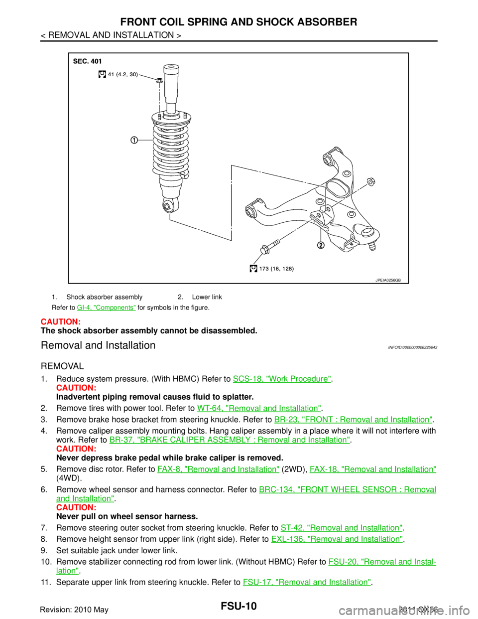
CAUTION:
The shock absorber assembly cannot be disassembled.
Removal and InstallationINFOID:0000000006225643
REMOVAL
1. Reduce system pressure. (With HBMC) Refer to SCS-18, "Work Procedure".
CAUTION:
Inadvertent piping removal causes fluid to splatter.
2. Remove tires with power tool. Refer to WT-64, "
Removal and Installation".
3. Remove brake hose bracket from steering knuckle. Refer to BR-23, "
FRONT : Removal and Installation".
4. Remove caliper assembly mounting bolts. Hang caliper assembly in a place where it will not interfere with work. Refer to BR-37, "
BRAKE CALIPER ASSEMBLY : Removal and Installation".
CAUTION:
Never depress brake pedal while brake caliper is removed.
5. Remove disc rotor. Refer to FA X - 8 , "
Removal and Installation" (2WD), FAX-18, "Removal and Installation"
(4WD).
6. Remove wheel sensor and harness connector. Refer to BRC-134, "
FRONT WHEEL SENSOR : Removal
and Installation".
CAUTION:
Never pull on wheel sensor harness.
7. Remove steering outer socket fr om steering knuckle. Refer to ST-42, "
Removal and Installation".
8. Remove height sensor from upper link (right side). Refer to EXL-136, "
Removal and Installation".
9. Set suitable jack under lower link.
10. Remove stabilizer connecting rod from lower link. (Without HBMC) Refer to FSU-20, "
Removal and Instal-
lation".
11. Separate upper link from steering knuckle. Refer to FSU-17, "
Removal and Installation".
1. Shock absorber assembly 2. Lower link
Refer to GI-4, "
Components" for symbols in the figure.
JPEIA0256GB
Revision: 2010 May2011 QX56
Page 2956 of 5598

FSU-14
< REMOVAL AND INSTALLATION >
LOWER LINK
LOWER LINK
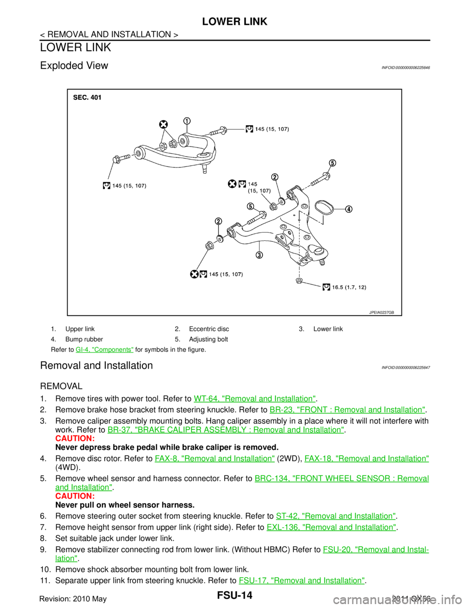
Exploded ViewINFOID:0000000006225646
Removal and InstallationINFOID:0000000006225647
REMOVAL
1. Remove tires with power tool. Refer to WT-64, "Removal and Installation".
2. Remove brake hose bracket from steering knuckle. Refer to BR-23, "
FRONT : Removal and Installation".
3. Remove caliper assembly mounting bolts. Hang caliper assembly in a place where it will not interfere with work. Refer to BR-37, "
BRAKE CALIPER ASSEMBLY : Removal and Installation".
CAUTION:
Never depress brake pedal while brake caliper is removed.
4. Remove disc rotor. Refer to FA X - 8 , "
Removal and Installation" (2WD), FAX-18, "Removal and Installation"
(4WD).
5. Remove wheel sensor and harness connector. Refer to BRC-134, "
FRONT WHEEL SENSOR : Removal
and Installation".
CAUTION:
Never pull on wheel sensor harness.
6. Remove steering outer socket fr om steering knuckle. Refer to ST-42, "
Removal and Installation".
7. Remove height sensor from upper link (right side). Refer to EXL-136, "
Removal and Installation".
8. Set suitable jack under lower link.
9. Remove stabilizer connecting rod from lower link. (Without HBMC) Refer to FSU-20, "
Removal and Instal-
lation".
10. Remove shock absorber mounting bolt from lower link.
11. Separate upper link from steering knuckle. Refer to FSU-17, "
Removal and Installation".
1. Upper link 2. Eccentric disc 3. Lower link
4. Bump rubber 5. Adjusting bolt
Refer to GI-4, "
Components" for symbols in the figure.
JPEIA0237GB
Revision: 2010 May2011 QX56
Page 2959 of 5598

UPPER LINKFSU-17
< REMOVAL AND INSTALLATION >
C
DF
G H
I
J
K L
M A
B
FSU
N
O P
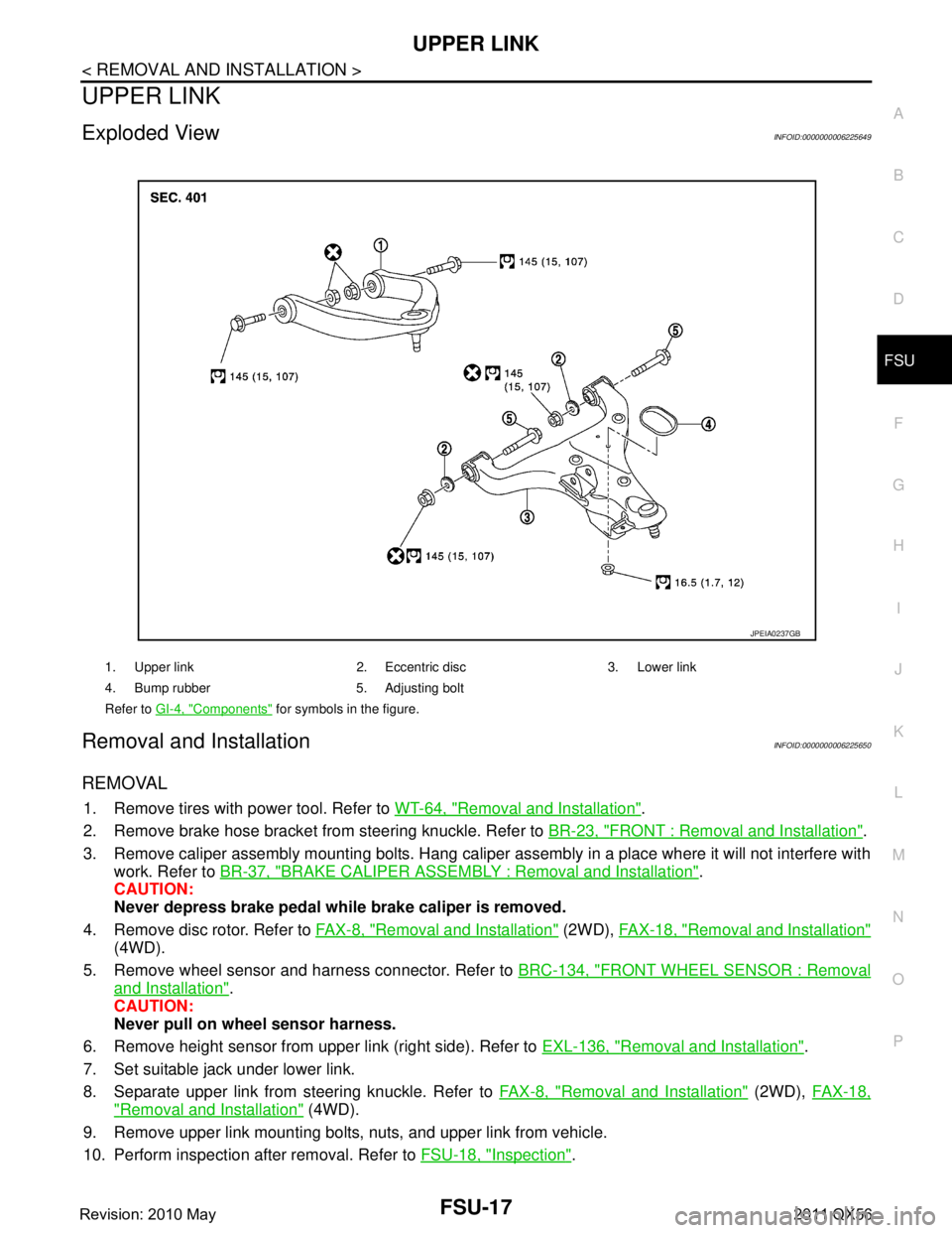
UPPER LINK
Exploded ViewINFOID:0000000006225649
Removal and InstallationINFOID:0000000006225650
REMOVAL
1. Remove tires with power tool. Refer to WT-64, "Removal and Installation".
2. Remove brake hose bracket from steering knuckle. Refer to BR-23, "
FRONT : Removal and Installation".
3. Remove caliper assembly mounting bolts. Hang caliper assembly in a place where it will not interfere with work. Refer to BR-37, "
BRAKE CALIPER ASSEMBLY : Removal and Installation".
CAUTION:
Never depress brake pedal while brake caliper is removed.
4. Remove disc rotor. Refer to FA X - 8 , "
Removal and Installation" (2WD), FAX-18, "Removal and Installation"
(4WD).
5. Remove wheel sensor and harness connector. Refer to BRC-134, "
FRONT WHEEL SENSOR : Removal
and Installation".
CAUTION:
Never pull on wheel sensor harness.
6. Remove height sensor from upper link (right side). Refer to EXL-136, "
Removal and Installation".
7. Set suitable jack under lower link.
8. Separate upper link from steering knuckle. Refer to FA X - 8 , "
Removal and Installation" (2WD), FAX-18,
"Removal and Installation" (4WD).
9. Remove upper link mounting bolts, nuts, and upper link from vehicle.
10. Perform inspection after removal. Refer to FSU-18, "
Inspection".
1. Upper link 2. Eccentric disc 3. Lower link
4. Bump rubber 5. Adjusting bolt
Refer to GI-4, "
Components" for symbols in the figure.
JPEIA0237GB
Revision: 2010 May2011 QX56