2011 INFINITI QX56 Head lamp
[x] Cancel search: Head lampPage 4567 of 5598
SE-108
< REMOVAL AND INSTALLATION >
FRONT SEAT
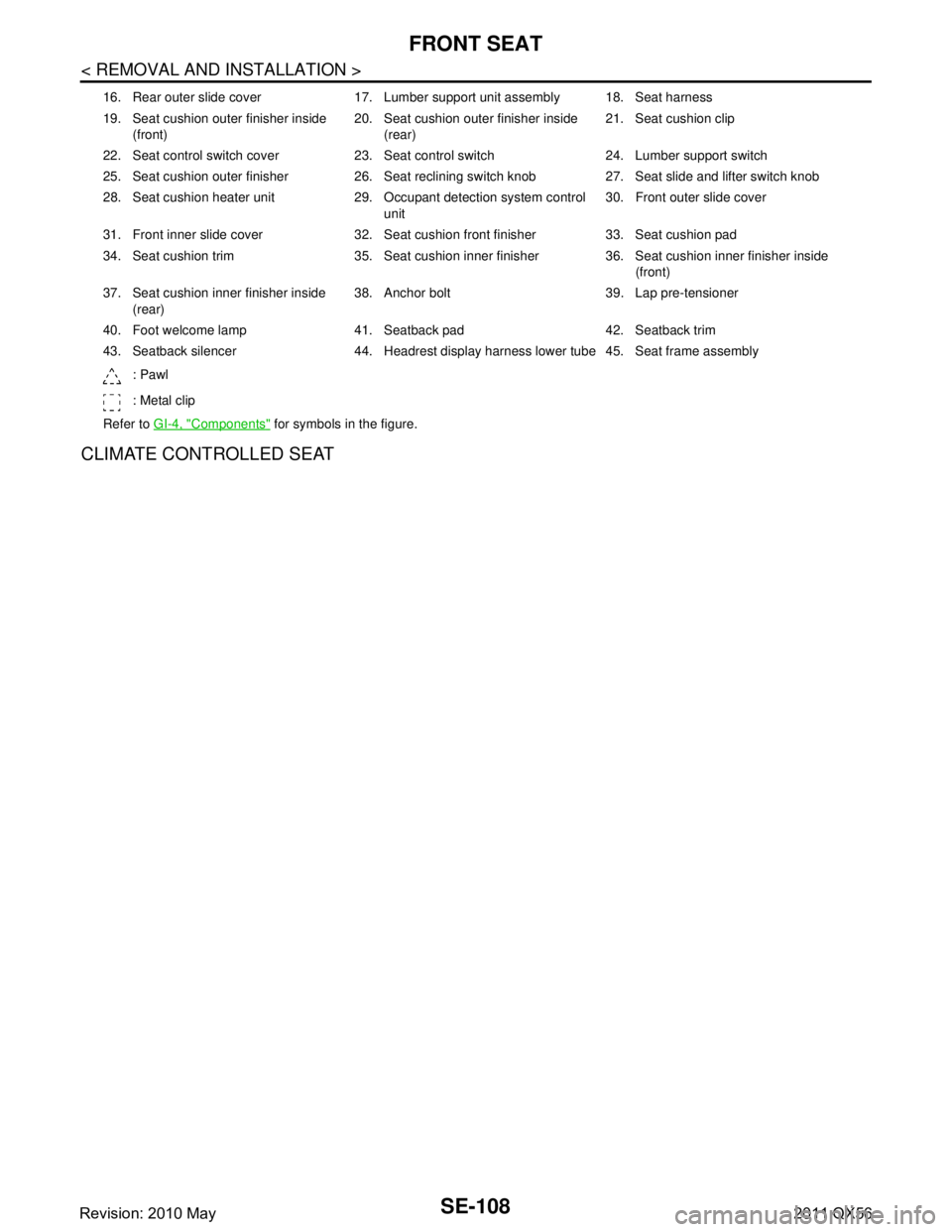
CLIMATE CONTROLLED SEAT
16. Rear outer slide cover 17. Lumber support unit assembly 18. Seat harness
19. Seat cushion outer finisher inside (front) 20. Seat cushion outer finisher inside
(rear) 21. Seat cushion clip
22. Seat control switch cover 23. Seat control switch 24. Lumber support switch
25. Seat cushion outer finisher 26. Seat reclining switch knob 27. Seat slide and lifter switch knob
28. Seat cushion heater unit 29. Occupant detection system control unit30. Front outer slide cover
31. Front inner slide cover 32. Seat cushion front finisher 33. Seat cushion pad
34. Seat cushion trim 35. Seat cushion inner finisher 36. Seat cushion inner finisher inside (front)
37. Seat cushion inner finisher inside (rear) 38. Anchor bolt 39. Lap pre-tensioner
40. Foot welcome lamp 41. Seatback pad 42. Seatback trim
43. Seatback silencer 44. Headrest display harness lower tube 45. Seat frame assembly : Pawl
: Metal clip
Refer to GI-4, "
Components" for symbols in the figure.
Revision: 2010 May2011 QX56
Page 4568 of 5598
FRONT SEATSE-109
< REMOVAL AND INSTALLATION >
C
DE
F
G H
I
K L
M A
B
SE
N
O P
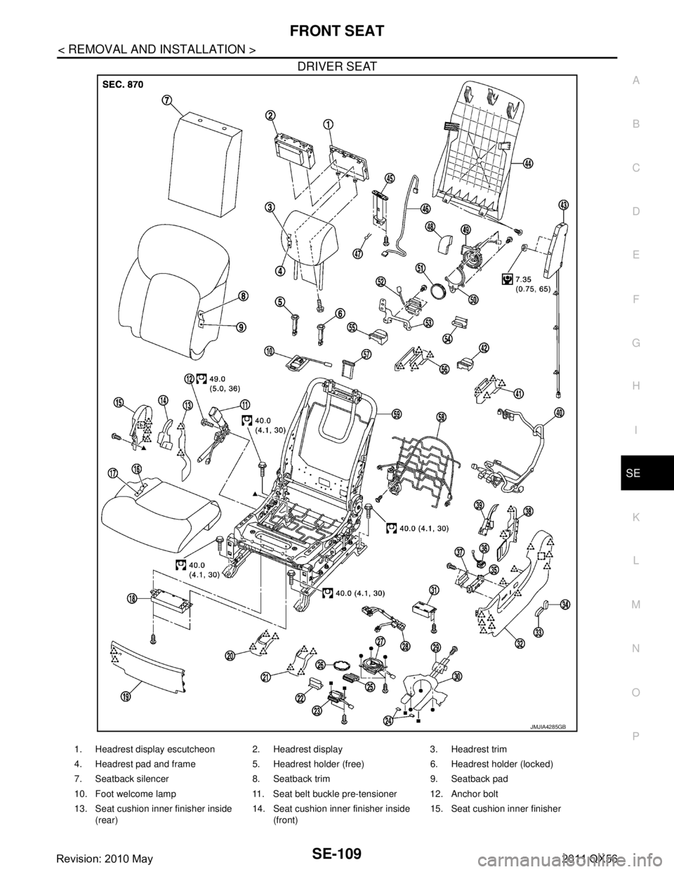
DRIVER SEAT
JMJIA4285GB
1. Headrest display escutcheon 2. Headrest display 3. Headrest trim
4. Headrest pad and frame 5. Headrest holder (free) 6. Headrest holder (locked)
7. Seatback silencer 8. Seatback trim 9. Seatback pad
10. Foot welcome lamp 11. Seat belt buckle pre-tensioner 12. Anchor bolt
13. Seat cushion inner finisher inside (rear) 14. Seat cushion inner finisher inside
(front) 15. Seat cushion inner finisher
Revision: 2010 May2011 QX56
Page 4571 of 5598
SE-112
< REMOVAL AND INSTALLATION >
FRONT SEAT
Removal and Installation
INFOID:0000000006217424
REMOVAL
CAUTION:
When removing and installing, use shop cloths to protect parts from damage.
When removing and installing, 2 workers are required so as to prevent it from dropping.
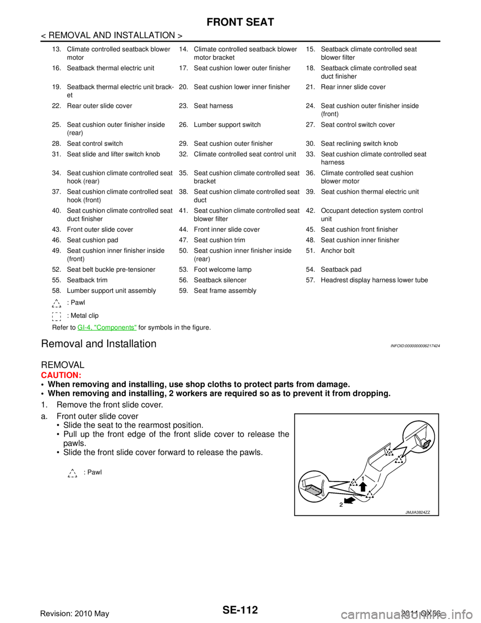
1. Remove the front slide cover.
a. Front outer slide cover Slide the seat to the rearmost position.
Pull up the front edge of the front slide cover to release the
pawls.
Slide the front slide cover forward to release the pawls.
13. Climate controlled seatback blower
motor 14. Climate controlled seatback blower
motor bracket 15. Seatback climate controlled seat
blower filter
16. Seatback thermal electric unit 17. Seat cushion lower outer finisher 18. Seatback climate controlled seat duct finisher
19. Seatback thermal electric unit brack- et 20. Seat cushion lower inner finisher 21. Rear inner slide cover
22. Rear outer slide cover 23. Seat harness 24. Seat cushion outer finisher inside (front)
25. Seat cushion outer finisher inside (rear) 26. Lumber support switch 27. Seat control switch cover
28. Seat control switch 29. Seat cushion outer finisher 30. Seat reclining switch knob
31. Seat slide and lifter switch knob 32. Climate controlled seat control unit 33. Seat cushion climate controlled seat harness
34. Seat cushion climate controlled seat hook (rear) 35. Seat cushion climate controlled seat
bracket 36. Climate controlled seat cushion
blower motor
37. Seat cushion climate controlled seat hook (front) 38. Seat cushion climate controlled seat
duct 39. Seat cushion thermal electric unit
40. Seat cushion climate controlled seat duct finisher 41. Seat cushion climate controlled seat
blower filter 42. Occupant detection system control
unit
43. Front outer slide cover 44. Front inner slide cover 45. Seat cushion front finisher
46. Seat cushion pad 47. Seat cushion trim 48. Seat cushion inner finisher
49. Seat cushion inner finisher inside (front) 50. Seat cushion inner finisher inside
(rear) 51. Anchor bolt
52. Seat belt buckle pre-tensioner 53. Foot welcome lamp 54. Seatback pad
55. Seatback trim 56. Seatback silencer 57. Headrest display harness lower tube
58. Lumber support unit assembly 59. Seat frame assembly : Pawl
: Metal clip
Refer to GI-4, "
Components" for symbols in the figure.
: Pawl
JMJIA3824ZZ
Revision: 2010 May2011 QX56
Page 4573 of 5598
SE-114
< REMOVAL AND INSTALLATION >
FRONT SEAT
SEATBACK
SEATBACK : Disassembly and AssemblyINFOID:0000000006217425
DISASSEMBLY
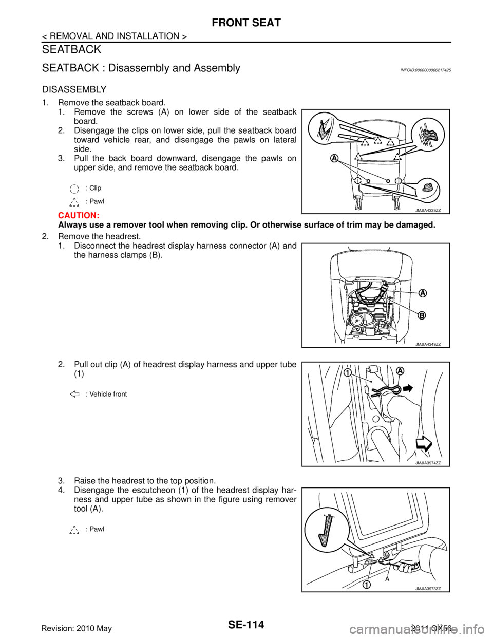
1. Remove the seatback board.1. Remove the screws (A) on lower side of the seatbackboard.
2. Disengage the clips on lower side, pull the seatback board toward vehicle rear, and disengage the pawls on lateral
side.
3. Pull the back board downward, disengage the pawls on upper side, and remove the seatback board.
CAUTION:
Always use a remover tool when removing clip. Or otherwise surface of trim may be damaged.
2. Remove the headrest. 1. Disconnect the headrest display harness connector (A) and
the harness clamps (B).
2. Pull out clip (A) of headrest display harness and upper tube (1)
3. Raise the headrest to the top position.
4. Disengage the escutcheon (1) of the headrest display har- ness and upper tube as shown in the figure using remover
tool (A).
: Clip
: Pawl
JMJIA4339ZZ
JMJIA4349ZZ
: Vehicle front
JMJIA3974ZZ
: Pawl
JMJIA3973ZZ
Revision: 2010 May2011 QX56
Page 4574 of 5598
FRONT SEATSE-115
< REMOVAL AND INSTALLATION >
C
DE
F
G H
I
K L
M A
B
SE
N
O P
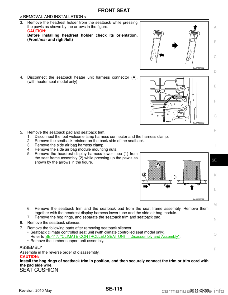
3. Remove the headrest holder from the seatback while pressing the pawls as shown by the arrows in the figure.
CAUTION:
Before installing headrest holder check its orientation.
(Front/rear and right/left)
4. Disconnect the seatback heater unit harness connector (A). (with heater seat model only)
5. Remove the seatback pad and seatback trim. 1. Disconnect the foot welcome lamp harness connector and the harness clamp.
2. Remove the seatback retainer on the back side of the seatback.
3. Remove the side air bag harness clamp.
4. Remove the side air bag module mounting nuts.
5. Remove the headrest display harness lower tube (1) from
the seat frame assembly (2) while pressing up the pawls as
shown by the arrows in the figure.
6. Remove the seatback trim and the seatback pad from the seat frame assembly. Remove them
together with the headrest display harness lower tube and the side air bag module.
7. Remove the hog rings, and separate the seatback trim and seatback pad.
6. Remove the seatback silencer.
7. Remove the following parts after removing seatback silencer. Seatback climate controlled seat unit (wit h climate controlled seat model only).
Refer to SE-117, "
CLIMATE CONTROLLED SEAT UNIT : Disassembly and Assembly".
Remove the lumber support unit assembly.
ASSEMBLY
Assemble in the reverse order of disassembly.
CAUTION:
Install the hog rings of seatback trim in position, and then securely connect the trim or trim cord with
the pad side wire.
SEAT CUSHION
JMJIA4073ZZ
JMJIA4326ZZ
JMJIA3976ZZ
Revision: 2010 May2011 QX56
Page 4576 of 5598
FRONT SEATSE-117
< REMOVAL AND INSTALLATION >
C
DE
F
G H
I
K L
M A
B
SE
N
O P
ASSEMBLY
Assemble in the reverse order of disassembly.
CAUTION:
Install the hog rings of seat cushion trim in positi on, and then securely connect the trim or trim cord
with the pad side wire.
CLIMATE CONTROLLED SEAT UNIT
CLIMATE CONTROLLED SEAT UNI T : Disassembly and AssemblyINFOID:0000000006217427
DISASSEMBLY
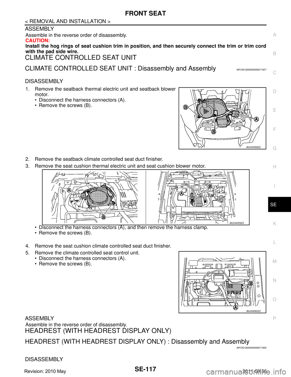
1. Remove the seatback thermal electric unit and seatback blower
motor.
Disconnect the harness connectors (A).
Remove the screws (B).
2. Remove the seatback climate controlled seat duct finisher.
3. Remove the seat cushion thermal electric unit and seat cushion blower motor.
Disconnect the harness connectors (A), and then remove the harness clamp.
Remove the screws (B).
4. Remove the seat cushion climat e controlled seat duct finisher.
5. Remove the climate controlled seat control unit. Disconnect the harness connectors (A).
Remove the screws (B).
ASSEMBLY
Assemble in the reverse order of disassembly.
HEADREST (WITH HEAD REST DISPLAY ONLY)
HEADREST (WITH HEADREST DISPLAY ONLY) : Disassembly and Assembly
INFOID:0000000006217428
DISASSEMBLY
JMJIA4058ZZ
JMJIA4059ZZ
JMJIA4060ZZ
Revision: 2010 May2011 QX56
Page 4610 of 5598
SEC-3
C
DE
F
G H
I
J
L
M A
B
SEC
N
O P
B260F ENGINE STATUS ............................... ..101
Description .......................................................... ..101
DTC Logic .............................................................101
Diagnosis Procedure .............................................101
B2612 STEERING STATUS .............................102
DTC Logic ........................................................... ..102
Diagnosis Procedure .............................................102
B2619 BCM ......................................................105
DTC Logic ........................................................... ..105
Diagnosis Procedure .............................................105
B26E9 STEERING STATUS ............................106
DTC Logic ........................................................... ..106
Diagnosis Procedure .............................................106
B26EF STEERING LOCK RELAY ...................107
DTC Logic ........................................................... ..107
Diagnosis Procedure .............................................107
B26F0 STEERING LOCK RELAY ...................109
DTC Logic ........................................................... ..109
Diagnosis Procedure .............................................109
B26F3 STARTER CONTROL RELAY .............111
DTC Logic ........................................................... ..111
Diagnosis Procedure .............................................111
B26F4 STARTER CONTROL RELAY .............112
DTC Logic ........................................................... ..112
Diagnosis Procedure .............................................112
B26F5 STEERING LOCK STATUS SWITCH ..113
DTC Logic .............................................................113
Diagnosis Procedure .............................................113
B26F7 BCM ......................................................116
DTC Logic ........................................................... ..116
Diagnosis Procedure .............................................116
B26F8 BCM ......................................................117
DTC Logic ........................................................... ..117
Diagnosis Procedure .............................................117
B26F9 CRANKING REQUEST CIRCUIT .........118
DTC Logic ........................................................... ..118
Diagnosis Procedure .............................................118
B26FA CRANKING REQUEST CIRCUIT ........120
DTC Logic ........................................................... ..120
Diagnosis Procedure .............................................120
B26FC KEY REGISTRATION ..........................122
DTC Logic ........................................................... ..122
Diagnosis Procedure .............................................122
B209F CRANKING REQUEST CIRCUIT .........123
DTC Logic ........................................................... ..123
Diagnosis Procedure .............................................123
B20A0 CRANKING REQUEST CIRCUIT .......125
DTC Logic ............................................................ ..125
Diagnosis Procedure .............................................125
B2108 STEERING LOCK RELAY ..................127
DTC Logic ..............................................................127
Diagnosis Procedure .............................................127
B2109 STEERING LOCK RELAY ..................128
DTC Logic ..............................................................128
Diagnosis Procedure .............................................128
B210A STEERING LOCK UNIT ......................129
DTC Logic ..............................................................129
Diagnosis Procedure .............................................129
B210B STARTER CONTROL RELAY ............131
DTC Logic ..............................................................131
Diagnosis Procedure .............................................131
B210C STARTER CONTROL RELAY ............132
DTC Logic ..............................................................132
Diagnosis Procedure .............................................132
B210D STARTER RELAY ..............................133
DTC Logic ..............................................................133
Diagnosis Procedure .............................................133
B210E STARTER RELAY ...............................134
DTC Logic ..............................................................134
Diagnosis Procedure .............................................134
B210F SHIFT POSITION/CLUTCH INTER-
LOCK SWITCH ...............................................
136
DTC Logic ..............................................................136
Diagnosis Procedure .............................................136
B2110 SHIFT POSITION/CLUTCH INTER-
LOCK SWITCH ...............................................
138
DTC Logic ..............................................................138
Diagnosis Procedure .............................................138
HEADLAMP FUNCTION .................................140
Component Function Check ..................................140
Diagnosis Procedure .............................................140
HOOD SWITCH ...............................................141
Component Function Check ................................141
Diagnosis Procedure ............................................141
Component Inspection ...........................................142
HORN FUNCTION ...........................................143
Component Function Check .............................. ..143
Diagnosis Procedure ............................................143
Component Inspection ...........................................145
SECURITY INDICATOR LAMP ......................146
Component Function Check ................................146
Diagnosis Procedure .............................................146
SYMPTOM DIAGNOSIS ............................148
Revision: 2010 May2011 QX56
Page 4625 of 5598
![INFINITI QX56 2011 Factory Service Manual
SEC-18
< SYSTEM DESCRIPTION >[WITH INTELLIGENT KEY SYSTEM]
SYSTEM
VEHICLE SECURITY SYSTEM : System Description
INFOID:0000000006226185
The vehicle security system has two alarm functions (theft wa INFINITI QX56 2011 Factory Service Manual
SEC-18
< SYSTEM DESCRIPTION >[WITH INTELLIGENT KEY SYSTEM]
SYSTEM
VEHICLE SECURITY SYSTEM : System Description
INFOID:0000000006226185
The vehicle security system has two alarm functions (theft wa](/manual-img/42/57033/w960_57033-4624.png)
SEC-18
< SYSTEM DESCRIPTION >[WITH INTELLIGENT KEY SYSTEM]
SYSTEM
VEHICLE SECURITY SYSTEM : System Description
INFOID:0000000006226185
The vehicle security system has two alarm functions (theft warning alarm and panic alarm), and reduces the
possibility of a theft or mischief by activating horns and headlamps intermittently.
The panic alarm does not start when the theft warning alarm is activating, and the panic alarm stops when
the theft warning alarm is activated.
The priority of the functions are as per the following.
THEFT WARNING ALARM
The theft warning alarm function activates horns and headlamps intermittently when BCM detects that any
door or hood is opened by unauthorized means, whil e the system is in the ARMED state.
Security indicator lamp on combination meter always blinks when power supply position is any position other
than ON. Security indicator lamp blinking warns that the vehicle is equipped with a vehicle security system.
Operation Flow
Priority Function
1 Theft warning alarm
2 Panic alarm
JMKIA5416GB
No. System state Switching condition
1 DISARMED to PRE-ARMED When all conditions of A and
one condition of B is satis-
fied. AB
Power supply position: OFF/LOCK
All doors: Closed
Hood: Closed All doors are locked by:
Door key cylinder LOCK switch
LOCK button of Intelligent Key
Door request switch
2 PRE-ARMED to ARMED When all of the following
conditions are satisfied for
30 seconds. Power supply position: OFF/LOCK
All doors: Locked
Hood: Closed
3 ARMED to ALARM When one condition of A and
one condition of B are satis-
fied. AB
Intelligent Key: Not used Any door: Open Hood: Open
4 DISARMED to PRE-RESET When all conditions of A and
one condition of B is satis-
fied. AB
Power supply position: OFF/LOCK
All doors: Closed
Hood: Open All doors are locked by:
Door key cylinder LOCK switch
LOCK button of Intelligent Key
Door request switch
5 PRE-ARMED to PRE-RESET When one of the following
conditions is satisfied. Hood: Open
Revision: 2010 May2011 QX56