2011 INFINITI QX56 Head lamp
[x] Cancel search: Head lampPage 3379 of 5598

INT-30
< REMOVAL AND INSTALLATION >
HEADLINING
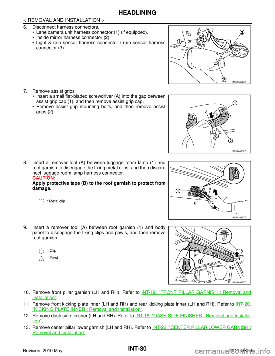
6. Disconnect harness connectors. Lane camera unit harness connector (1) (if equipped).
Inside mirror harness connector (2).
Light & rain sensor harness connector / rain sensor harness
connector (3).
7. Remove assist grips Insert a small flat-bladed screwdriver (A) into the gap between
assist grip cap (1), and then remove assist grip cap.
Remove assist grip mounting bolts, and then remove assist grips (2).
8. Insert a remover tool (A) between luggage room lamp (1) and roof garnish to disengage the fixing metal clips, and then discon-
nect luggage room lamp harness connector.
CAUTION:
Apply protective tape (B) to the roof garnish to protect from
damage.
9. Insert a remover tool (A) between roof garnish (1) and body panel to disengage the fixing clips and pawls, and then remove
roof garnish.
10. Remove front pillar garnish (LH and RH). Refer to INT-19, "
FRONT PILLAR GARNISH : Removal and
Installation".
11. Remove front kicking plate inner (LH and RH) and rear kicking plate inner (LH and RH). Refer to INT-20,
"KICKING PLATE INNER : Removal and Installation".
12. Remove dash side finisher (LH and RH). Refer to INT-18, "
DASH SIDE FINISHER : Removal and Installa-
tion".
13. Remove center pillar lower garnish (LH and RH). Refer to INT-22, "
CENTER PILLAR LOWER GARNISH :
Removal and Installation".
JMJIA4054ZZ
JMJIA4063ZZ
: Metal clip
JMLIA1059ZZ
: Clip
: Pawl
JMJIA4066ZZ
Revision: 2010 May2011 QX56
Page 3380 of 5598

HEADLININGINT-31
< REMOVAL AND INSTALLATION >
C
DE
F
G H
I
K L
M A
B
INT
N
O P
14. Remove luggage side lower finisher (LH and RH). Refer to INT-36, "LUGGAGE SIDE LOWER FINISHER
: Removal and Installation".
15. Remove front body side welt (LH and RH) and rear body side welt (LH and RH). Refer to INT-20, "
BODY
SIDE WELT : Removal and Installation".
16. Remove center pillar upper garnish (LH and RH). Refer to INT-22, "
CENTER PILLAR UPPER GARNISH :
Removal and Installation".
17. Remove rear pillar finisher (LH and RH). Refer to INT-37, "
REAR PILLAR FINISHER : Removal and
Installation".
18. Remove back pillar garnish (LH and RH). Refer to INT-37, "
BACK PILLAR GARNISH : Removal and
Installation".
19. Remove luggage side upper finisher (LH and RH). Refer to INT-38, "
LUGGAGE SIDE UPPER FINISHER
: Removal and Installation".
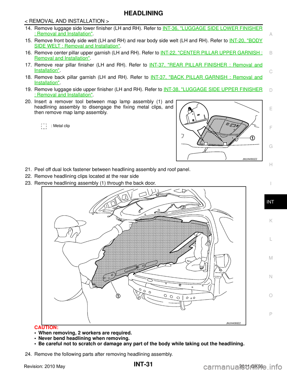
20. Insert a remover tool between map lamp assembly (1) and headlining assembly to disengage the fixing metal clips, and
then remove map lamp assembly.
21. Peel off dual lock fastener between headlining assembly and roof panel.
22. Remove headlining clips located at the rear side
23. Remove headlining assembly (1) through the back door.
CAUTION:
When removing, 2 workers are required.
Never bend headlini ng when removing.
Be careful not to scratch or damage any part of the body while taking out the headlining.
24. Remove the following parts after removing headlining assembly.
: Metal clip
JMJIA4062ZZ
JMJIA4068ZZ
Revision: 2010 May2011 QX56
Page 3381 of 5598

INT-32
< REMOVAL AND INSTALLATION >
HEADLINING
Personal lamp assembly. Refer to INL-77, "Removal and Installation".
Rear ventilator grille assembly. Refer to VTL-13, "
REAR VENTILATOR GRILLE : Removal and Installa-
tion".
Headlining harness.
INSTALLATION
Note the following items, and install in the reverse order of removal.
CAUTION:
Be careful not to bend h eadlining when installing.
First install metal clips of map lamp assembly and cl ips of the rear end of headlining for positioning.
Revision: 2010 May2011 QX56
Page 3433 of 5598
![INFINITI QX56 2011 Factory Service Manual
LAN
TROUBLE DIAGNOSISLAN-13
< SYSTEM DESCRIPTION > [CAN FUNDAMENTAL]
C
D
E
F
G H
I
J
K L
B A
O P
N
NOTE:
When data link connector branch line is open, transmi
ssion and reception of CAN communicati INFINITI QX56 2011 Factory Service Manual
LAN
TROUBLE DIAGNOSISLAN-13
< SYSTEM DESCRIPTION > [CAN FUNDAMENTAL]
C
D
E
F
G H
I
J
K L
B A
O P
N
NOTE:
When data link connector branch line is open, transmi
ssion and reception of CAN communicati](/manual-img/42/57033/w960_57033-3432.png)
LAN
TROUBLE DIAGNOSISLAN-13
< SYSTEM DESCRIPTION > [CAN FUNDAMENTAL]
C
D
E
F
G H
I
J
K L
B A
O P
N
NOTE:
When data link connector branch line is open, transmi
ssion and reception of CAN communication signals
are not affected. Therefore, no symptoms occur. However, be sure to repair malfunctioning circuit.
The model (all units on CAN communication system are Diag on CAN) cannot perform CAN diagnosis with
CONSULT-III if the following error occurs. The error is judged by the symptom.
Example: Main Line Between Data Link Connector and ABS Actuator and Electr ic Unit (Control Unit) Open Circuit
Unit name Major symptom
ECM
Normal operation.
BCM
EPS control unit
Combination meter
ABS actuator and electric
unit (control unit)
TCM
IPDM E/R
Error Difference of symptom
Data link connector branch line open circuit Normal operation.
CAN-H, CAN-L harness short-circuit Most of the units which are connected to the CAN communication
system enter fail-safe mode or are deactivated.
SKIB8740E
Unit name Major symptom
ECM Engine torque limiting is affected, and shift harshness increases.
BCM Reverse warning chime does not sound.
The front wiper moves under continuous operation mode even though the front wip-
er switch being in the intermittent position.
EPS control unit The steering effort increases.
Combination meter The shift position indicator and OD OFF indicator turn OFF.
The speedometer is inoperative.
The odo/trip meter stops.
ABS actuator and electric unit (control unit) Normal operation.
TCM No impact on operation.
IPDM E/R When the ignition switch is ON,
The headlamps (Lo) turn ON.
The cooling fan continues to rotate.
Revision: 2010 May2011 QX56
Page 3434 of 5598
![INFINITI QX56 2011 Factory Service Manual
LAN-14
< SYSTEM DESCRIPTION >[CAN FUNDAMENTAL]
TROUBLE DIAGNOSIS
Example: CAN-H, CAN-L Harness Short Circuit
CAN Diagnosis with CONSULT-IIIINFOID:0000000006220519
CAN diagnosis on CONSULT-III extract INFINITI QX56 2011 Factory Service Manual
LAN-14
< SYSTEM DESCRIPTION >[CAN FUNDAMENTAL]
TROUBLE DIAGNOSIS
Example: CAN-H, CAN-L Harness Short Circuit
CAN Diagnosis with CONSULT-IIIINFOID:0000000006220519
CAN diagnosis on CONSULT-III extract](/manual-img/42/57033/w960_57033-3433.png)
LAN-14
< SYSTEM DESCRIPTION >[CAN FUNDAMENTAL]
TROUBLE DIAGNOSIS
Example: CAN-H, CAN-L Harness Short Circuit
CAN Diagnosis with CONSULT-IIIINFOID:0000000006220519
CAN diagnosis on CONSULT-III extracts the root
cause by receiving the following information.
Response to the system call
Control unit diagnosis information
Self-diagnosis
CAN diagnostic support monitor
SKIB8741E
Unit name Major symptom
ECM Engine torque limiting is affected, and shift harshness increases.
Engine speed drops.
BCM Reverse warning chime does not sound.
The front wiper moves under continuous operation mode even though the front
wiper switch being in the intermittent position.
The room lamp does not turn ON.
The engine does not start (if an error or malfunction occurs while turning the igni- tion switch OFF.)
The steering lock does not release (if an error or malfunction occurs while turning the ignition switch OFF.)
EPS control unit The steeri ng effort increases.
Combination meter The tachometer and the speedometer do not move.
Warning lamps turn ON.
Indicator lamps do not turn ON.
ABS actuator and electric unit (control unit) Normal operation.
TCM No impact on operation.
IPDM E/R When the ignition switch is ON,
The headlamps (Lo) turn ON.
The cooling fan continues to rotate.
Revision: 2010 May2011 QX56
Page 3450 of 5598
![INFINITI QX56 2011 Factory Service Manual
LAN-30
< SYSTEM DESCRIPTION >[CAN]
SYSTEM
P range signal T R R
R range signal T R R
Shift position signal R R T R R R R R
Tow mode indicator lamp
signalTR
Pre-roll over signal T R
Pre-tensioner oper INFINITI QX56 2011 Factory Service Manual
LAN-30
< SYSTEM DESCRIPTION >[CAN]
SYSTEM
P range signal T R R
R range signal T R R
Shift position signal R R T R R R R R
Tow mode indicator lamp
signalTR
Pre-roll over signal T R
Pre-tensioner oper](/manual-img/42/57033/w960_57033-3449.png)
LAN-30
< SYSTEM DESCRIPTION >[CAN]
SYSTEM
P range signal T R R
R range signal T R R
Shift position signal R R T R R R R R
Tow mode indicator lamp
signalTR
Pre-roll over signal T R
Pre-tensioner operation
signal TR
AFS OFF indicator lamp
signal TR
A/C switch operation signal T R
Rear window defogger
switch signal TR
System selection signal T R
System setting signal TR R
RT
RT
Automatic back door re-
quest signal TR
Back door lock status signal T R
Buzzer output signal TR
RT
Buzzer request signal TR
RT
Dimmer signal T R R
Door switch signal T R R R R
Door unlock signal T R
Front fog light request sig-
nal TR
Front wiper request signal T R R
Handle position signal T R
Headlamp washer request
signal TR
High beam request signal T R R
Horn reminder signal T R
Ignition switch ON signal TRRR
RT
Ignition switch signal T R
Interlock/PNP switch signal TR
RT
Key ID signal T R
Key switch signal T R
Key warning lamp signal T R
Low beam request signal T R Signal name
ECM
4WD
ABS
TCM
A-BAG
AFSAV
BCM
CGW
HVAC
M&A
STRG
TPMS
IPDM-E ADP
PSB
E-SUS ICC
PWBD
Revision: 2010 May2011 QX56
Page 3674 of 5598

MA-4
< PERIODIC MAINTENANCE >
GENERAL MAINTENANCE
PERIODIC MAINTENANCE
GENERAL MAINTENANCE
Explanation of General MaintenanceINFOID:0000000006287728
General maintenance includes those items which shoul d be checked during the normal day-to-day operation
of the vehicle. They are essential if the vehicle is to continue operating properly. The owners can perform
checks and inspections themselves or have their INFINITI dealers do them.
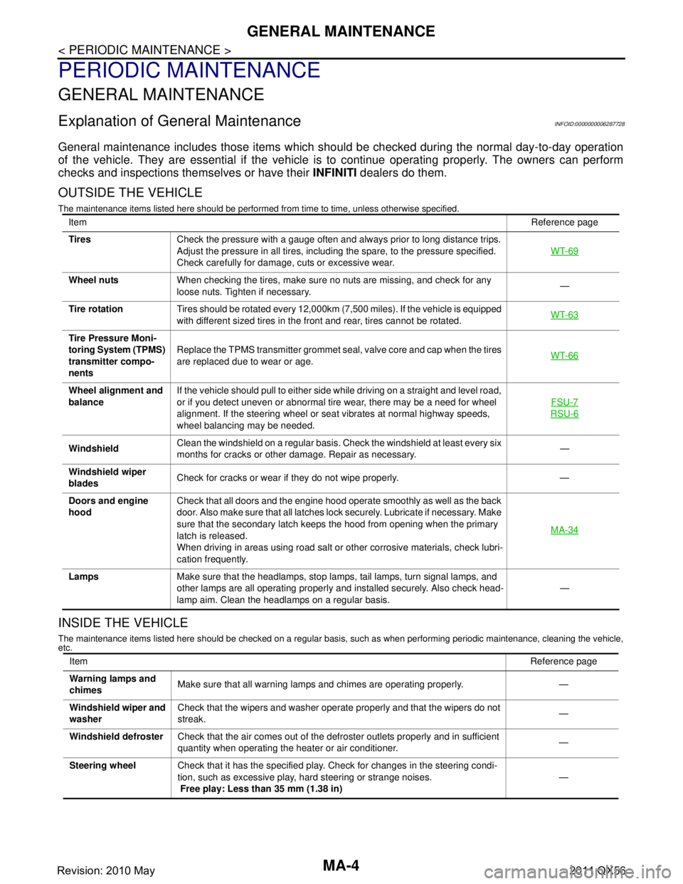
OUTSIDE THE VEHICLE
The maintenance items listed here should be performed fr om time to time, unless otherwise specified.
INSIDE THE VEHICLE
The maintenance items listed here should be checked on a regular basis, such as when performing periodic maintenance, cleaning the vehicle,
etc.
Item Reference page
Tires Check the pressure with a gauge often and always prior to long distance trips.
Adjust the pressure in all tires, including the spare, to the pressure specified.
Check carefully for damage, cuts or excessive wear. WT-69
Wheel nuts
When checking the tires, make sure no nuts are missing, and check for any
loose nuts. Tighten if necessary. —
Tire rotation Tires should be rotated every 12,000km (7,500 miles). If the vehicle is equipped
with different sized tires in the front and rear, tires cannot be rotated. WT-63
Tire Pressure Moni-
toring System (TPMS)
transmitter compo-
nentsReplace the TPMS transmitter grommet seal, valve core and cap when the tires
are replaced due to wear or age.
WT-66
Wheel alignment and
balanceIf the vehicle should pull to either side while driving on a straight and level road,
or if you detect uneven or abnormal tire wear, there may be a need for wheel
alignment. If the steering wheel or seat vibrates at normal highway speeds,
wheel balancing may be needed. FSU-7
RSU-6
Windshield
Clean the windshield on a regular basis. Check the windshield at least every six
months for cracks or other damage. Repair as necessary. —
Windshield wiper
blades Check for cracks or wear if they do not wipe properly. —
Doors and engine
hood Check that all doors and the engine hood operate smoothly as well as the back
door. Also make sure that all latches lock securely. Lubricate if necessary. Make
sure that the secondary latch keeps the hood from opening when the primary
latch is released.
When driving in areas using road salt or other corrosive materials, check lubri-
cation frequently. MA-34
Lamps
Make sure that the headlamps, stop lamps, tail lamps, turn signal lamps, and
other lamps are all operating properly and installed securely. Also check head-
lamp aim. Clean the headlamps on a regular basis. —
Item
Reference page
Warning lamps and
chimes Make sure that all warning lamps and chimes are operating properly. —
Windshield wiper and
washer Check that the wipers and washer operate properly and that the wipers do not
streak.
—
Windshield defroster Check that the air comes out of the defroster outlets properly and in sufficient
quantity when operating the heater or air conditioner. —
Steering wheel Check that it has the specified play. Check for changes in the steering condi-
tion, such as excessive play, hard steering or strange noises.
Free play: Less than 35 mm (1.38 in) —
Revision: 2010 May2011 QX56
Page 3775 of 5598
![INFINITI QX56 2011 Factory Service Manual
MWI-32
< SYSTEM DESCRIPTION >
DIAGNOSIS SYSTEM (COMBINATION METER)
AIR PRES W/L
[On/Off]Status of low tire pressure warning lamp judged from low tire pressure warning
lamp signal received from BCM w INFINITI QX56 2011 Factory Service Manual
MWI-32
< SYSTEM DESCRIPTION >
DIAGNOSIS SYSTEM (COMBINATION METER)
AIR PRES W/L
[On/Off]Status of low tire pressure warning lamp judged from low tire pressure warning
lamp signal received from BCM w](/manual-img/42/57033/w960_57033-3774.png)
MWI-32
< SYSTEM DESCRIPTION >
DIAGNOSIS SYSTEM (COMBINATION METER)
AIR PRES W/L
[On/Off]Status of low tire pressure warning lamp judged from low tire pressure warning
lamp signal received from BCM with CAN communication line.
KEY G/Y W/L
[On/Off] Status of KEY warning lamp
(Green/Yellow) detected from KEY warning lamp sig-
nal is received from BCM via CAN communication.
KEY KNOB W/L
[Off] This item is displayed, but cannot be monitored.
AFS OFF IND
[On/Off] Status of AFS OFF indicator lamp judged from AFS OFF indicator lamp signal re-
ceived from AFS control unit with CAN communication line.
DDS
* W/L
[Off] This item is displayed, but cannot be monitored.
LANE W/L
[On/Off] Status of lane departure warning lamp judged from lane departure warning lamp
signal received from ADAS control unit with CAN communication line.
LDP IND
[On/Off] Status of LDP ON indicator lamp judged from LDP ON indicator lamp signal re-
ceived from ADAS control unit with CAN communication line.
AT P W / L
[On/Off] Status of ATP warning lamp judged from ATP warning lamp signal received from
4WD control unit with CAN communication line.
DCA IND
[Off] This item is displayed, but cannot be monitored.
CHECK SUS IND
[On/Off] Status of CK SUSP indicator lamp judged from CK SUSP indicator lamp signal re-
ceived from E-SUS control unit with CAN communication line.
LCD
[B&P N, B&P I, ID NG, ROTAT, SFT
P, INSRT, BATT, NO KY, OUTKY, LK
WN] Displays status of Intelligent Key system warning judged from meter display signal
received from BCM with CAN communication line.
ACC TARGET
[On/Off] Status of vehicle ahead detection indicator judged from meter display signal re-
ceived from ADAS control unit with CAN communication line.
ACC DISTANCE
[Off, Short, Middle, Long] Status of set distance indicator judged from meter display signal received from
ADAS control unit with
CAN communication line.
ACC OWN VHL
[On/Off] Status of own vehicle indicator judged from meter display signal received from
ADAS control unit with
CAN communication line.
ACC SET SPEED
[Off, km/h] Status of set vehicle speed indicator judged from meter display signal received
from ADAS control unit with CAN communication line.
ACC UNIT
[On/Off] Status of display unit judged from meter display signal received from ADAS con-
trol unit with CAN communication line.
SHIFT IND
[P, R, N, D, M1, M2, M3, M4, M5, M6,
M7] Status of shift position indicator judged from shift position signal and manual mode
indicator signal received from TCM with CAN communication line.
4WD IND
[AUTO, LOCK, 2W, 4Lo, HL1, HL2,
MALF] Status of 4WD indicator judged from 4WD indicator signal received from 4WD
control unit with CAN communication line.
BSW IND
[Off] This item is displayed, but cannot be monitored.
BSW W/L
[On/Off] Status of BSW warning lamp (orange) judged from BSW warning lamp signal re-
ceived from ADAS control unit with CAN communication line.
AT S MODE SW
[On/Off] Status of snow mode switch.
M RANGE SW
[On/Off] Status of manual mode switch.
NM RANGE SW
[On/Off] Status of non-manual mode switch.
AT SFT UP SW
[On/Off] Status of manual mode shift up switch.
Display item [Unit]
MAIN
SIGNALS Description
Revision: 2010 May2011 QX56