2011 INFINITI QX56 key
[x] Cancel search: keyPage 3282 of 5598

DIAGNOSIS SYSTEM (BCM)INL-15
< SYSTEM DESCRIPTION >
C
DE
F
G H
I
J
K
M A
B
INL
N
O P
ACTIVE TEST
BATTERY SAVER
BATTERY SAVER : CONSULT-III Function (BCM - BATTERY SAVER)INFOID:0000000006216060
WORK SUPPORT
*:Factory setting PUSH SW
[On/Off]
The switch status input from push-button ignition switch
UNLK SEN -DR
[On/Off] Driver door unlock status input from unlock sensor
DOOR SW-DR
[On/Off] The switch status input from door switch (driver side)
DOOR SW-AS
[On/Off] The switch status input from door switch (passenger side)
DOOR SW-RR
[On/Off] The switch status input from rear door switch RH
DOOR SW- RL
[On/Off] The switch status input from rear door switch LH
DOOR SW- BK
[On/Off] The switch status input from back door switch
CDL LOCK SW
[On/Off] Lock switch status input from door lock and unlock switch
CDL UNLOCK SW
[On/Off] Unlock switch status input from door lock and unlock switch
KEY CYL LK-SW
[On/Off] Lock switch status received from door key cylinder switch
KEY CYL UN-SW
[On/Off] Unlock switch status received from door key cylinder switch
TRNK/HAT MNTR
[On/Off] NOTE:
The item is indicated, but not monitored.
RKE-LOCK
[On/Off] Lock signal status received from remote keyless entry receiver
RKE-UNLOCK
[On/Off] Unlock signal status received from remote keyless entry receiver
Monitor item
[Unit] Description
Test item Operation Description
INT LAMP OnOutputs the interior room lamp control signal to turn the interior room lamps ON.
[Map lamp, personal lamp, foot lamp (when applicable lamps switch is in DOOR po-
sition.)]
Off Stops the interior room lamp control signal to turn the interior room lamps OFF.
STEP LAMP TEST On Outputs the step lamp control signal to turn the step lamps ON.
Off Stops the step lamp control signal to turn the step lamps ON.
Service item Setting item Setting
ROOM LAMP TIMER SET MODE 1
*30 min.
Sets the interior room lamp battery saver timer operating
time.
MODE 2 60 min.
BATTERY SAVER SET On
*With the exterior lamp battery saver function
Off Without the exterior lamp battery saver function
Revision: 2010 May2011 QX56
Page 3283 of 5598
![INFINITI QX56 2011 Factory Service Manual
INL-16
< SYSTEM DESCRIPTION >
DIAGNOSIS SYSTEM (BCM)
DATA MONITOR
ACTIVE TEST
*: Each lamp switch is in ON position.Monitor item
[Unit] Description
REQ SW-DR
[On/Off] The switch status input from doo INFINITI QX56 2011 Factory Service Manual
INL-16
< SYSTEM DESCRIPTION >
DIAGNOSIS SYSTEM (BCM)
DATA MONITOR
ACTIVE TEST
*: Each lamp switch is in ON position.Monitor item
[Unit] Description
REQ SW-DR
[On/Off] The switch status input from doo](/manual-img/42/57033/w960_57033-3282.png)
INL-16
< SYSTEM DESCRIPTION >
DIAGNOSIS SYSTEM (BCM)
DATA MONITOR
ACTIVE TEST
*: Each lamp switch is in ON position.Monitor item
[Unit] Description
REQ SW-DR
[On/Off] The switch status input from door request switch (driver side)
REQ SW-AS
[On/Off] The switch status input from door request switch (passenger side)
REQ SW-RR
[On/Off] NOTE:
The item is indicated, but not monitored.
REQ SW-RL
[On/Off]
PUSH SW
[On/Off] The switch status input from push-button ignition switch
UNLK SEN-DR
[On/Off] Driver door unlock status input from unlock sensor
DOOR SW-DR
[On/Off] The switch status input from door switch (driver side)
DOOR SW-AS
[On/Off] The switch status input from door switch (passenger side)
DOOR SW-RR
[On/Off] The switch status input from rear door switch RH
DOOR SW- RL
[On/Off] The switch status input from rear door switch LH
DOOR SW- BK
[On/Off] The switch status input from back door switch
CDL LOCK SW
[On/Off] Lock switch status input from door lock and unlock switch
CDL UNLOCK SW
[On/Off] Unlock switch status input from door lock and unlock switch
KEY CYL LK-SW
[On/Off] Lock switch status received from door key cylinder switch
KEY CYL UN-SW
[On/Off] Unlock switch status received from door key cylinder switch
TRNK/HAT MNTR
[On/Off] NOTE:
The item is indicated, but not monitored.
RKE-LOCK
[On/Off] Lock signal status received from remote keyless entry receiver
RKE-UNLOCK
[On/Off] Unlock signal status received from remote keyless entry receiver
Test item Operation Description
BATTERY SAVER Off Cuts the interior room lamp power supply to turn interior room lamps OFF.
On Outputs the interior room lamp power supply to turn interior room lamps ON.*
Revision: 2010 May2011 QX56
Page 3332 of 5598

PUSH-BUTTON IGNITION SWITCH ILLUMINATION CIRCUIT
INL-65
< DTC/CIRCUIT DIAGNOSIS >
C
D E
F
G H
I
J
K
M A
B
INL
N
O P
PUSH-BUTTON IGNITION SWIT CH ILLUMINATION CIRCUIT
Component Function CheckINFOID:0000000006265016
1.CHECK PUSH-BUTTON IGNITION SWITCH ILLUMINATION OPERATION
CONSULT-III ACTIVE TEST
1. Turn the ignition switch ON.
2. Select “ENGINE SW ILLUMI” of BCM (I NTELLIGENT KEY) active test item.
3. With operating the test items, check that the pus h-button ignition switch illumination turns ON/OFF.
Does the push-button ignition switch illumination turn ON/OFF?
YES >> Push-button ignition switch illumination circuit is normal.
NO >> Refer to INL-65, "
Diagnosis Procedure".
Diagnosis ProcedureINFOID:0000000006265017
1.CHECK PUSH-BUTTON IGNITION SWITCH ILLUMINATION POWER SUPPLY OUTPUT
1. Turn ignition switch OFF.
2. Lighting switch OFF.
3. Disconnect push-button ignition switch connector.
4. Check voltage between push-button ignition switch harness connector and ground.
Is the inspection result normal?
YES >> GO TO 4.
NO >> GO TO 2.
2.CHECK PUSH-BUTTON IGNITION SWITCH ILLU MINATION POWER SUPPLY OPEN CIRCUIT
1. Turn the ignition switch OFF.
2. Disconnect BCM connector.
3. Check continuity between BCM harness connector and the push-button ignition switch harness connector.
Is the inspection result normal?
YES >> GO TO 3.
NO >> Repair or replace harnesses.
3.CHECK PUSH-BUTTON IGNITION SWITCH ILLU MINATION POWER SUPPLY SHORT CIRCUIT
Check continuity between BCM harness connector and ground.
Is the inspection result normal?
YES >> Replace BCM. Refer to BCS-81, "Removal and Installation".
On : Push-button ignition
switch illumination ON
Off : Push-button ignition switch illumination OFF
(+)
(–) Condition Vo l ta g e
(Approx.)
Push-button ignition switch
Connector Terminal
M101 3 Ground Push-button ignition
switch illuminationON Condition 12 V
OFF Condition 0 V
BCM Push-button ignition switch Continuity
Connector Terminal Connector Terminal
M71 90 M101 3 Existed
BCM GroundContinuity
Connector Terminal
M71 90 Not existed
Revision: 2010 May2011 QX56
Page 3414 of 5598

IP-24
< REMOVAL AND INSTALLATION >
CENTER CONSOLE ASSEMBLY
CONSOLE FINISHER ASSEMBLY
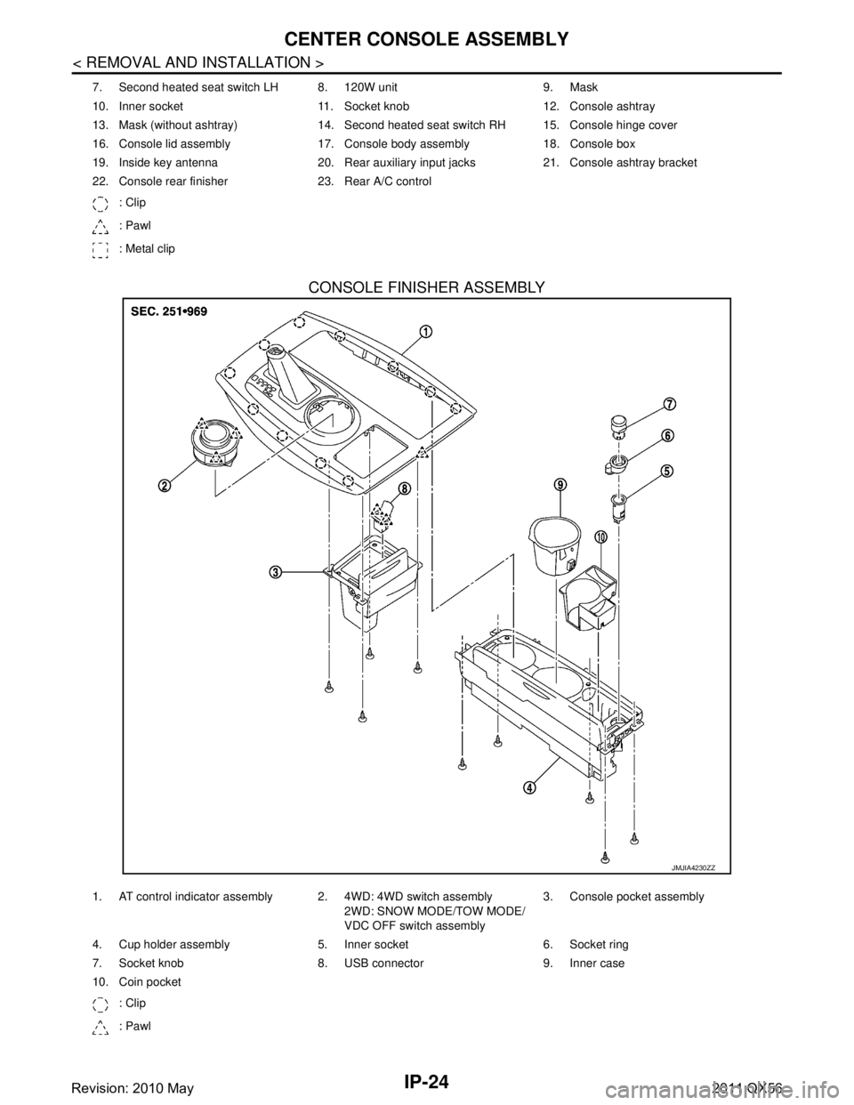
7. Second heated seat switch LH 8. 120W unit 9. Mask
10. Inner socket 11. Socket knob 12. Console ashtray
13. Mask (without ashtray) 14. Second heated seat switch RH 15. Console hinge cover
16. Console lid assembly 17. Console body assembly 18. Console box
19. Inside key antenna 20. Rear auxiliary input jacks 21. Console ashtray bracket
22. Console rear finisher 23. Rear A/C control: Clip
: Pawl
: Metal clip
JMJIA4230ZZ
1. AT control indicator assembly 2. 4WD: 4WD switch assembly 2WD: SNOW MODE/TOW MODE/
VDC OFF switch assembly3. Console pocket assembly
4. Cup holder assembly 5. Inner socket 6. Socket ring
7. Socket knob 8. USB connector 9. Inner case
10. Coin pocket : Clip
: Pawl
Revision: 2010 May2011 QX56
Page 3450 of 5598
![INFINITI QX56 2011 Factory Service Manual
LAN-30
< SYSTEM DESCRIPTION >[CAN]
SYSTEM
P range signal T R R
R range signal T R R
Shift position signal R R T R R R R R
Tow mode indicator lamp
signalTR
Pre-roll over signal T R
Pre-tensioner oper INFINITI QX56 2011 Factory Service Manual
LAN-30
< SYSTEM DESCRIPTION >[CAN]
SYSTEM
P range signal T R R
R range signal T R R
Shift position signal R R T R R R R R
Tow mode indicator lamp
signalTR
Pre-roll over signal T R
Pre-tensioner oper](/manual-img/42/57033/w960_57033-3449.png)
LAN-30
< SYSTEM DESCRIPTION >[CAN]
SYSTEM
P range signal T R R
R range signal T R R
Shift position signal R R T R R R R R
Tow mode indicator lamp
signalTR
Pre-roll over signal T R
Pre-tensioner operation
signal TR
AFS OFF indicator lamp
signal TR
A/C switch operation signal T R
Rear window defogger
switch signal TR
System selection signal T R
System setting signal TR R
RT
RT
Automatic back door re-
quest signal TR
Back door lock status signal T R
Buzzer output signal TR
RT
Buzzer request signal TR
RT
Dimmer signal T R R
Door switch signal T R R R R
Door unlock signal T R
Front fog light request sig-
nal TR
Front wiper request signal T R R
Handle position signal T R
Headlamp washer request
signal TR
High beam request signal T R R
Horn reminder signal T R
Ignition switch ON signal TRRR
RT
Ignition switch signal T R
Interlock/PNP switch signal TR
RT
Key ID signal T R
Key switch signal T R
Key warning lamp signal T R
Low beam request signal T R Signal name
ECM
4WD
ABS
TCM
A-BAG
AFSAV
BCM
CGW
HVAC
M&A
STRG
TPMS
IPDM-E ADP
PSB
E-SUS ICC
PWBD
Revision: 2010 May2011 QX56
Page 3667 of 5598

LU-14
< REMOVAL AND INSTALLATION >
OIL PUMP
5. Remove the oil pump drive spacer. Hold and remove the flat space of the oil pump drive spacer bypulling it forward.
6. Remove the oil pump. Refer to LU-13, "
Exploded View".
INSTALLATION
1. Install the oil pump.
2. Install the oil pump drive spacer as follows:
When inserting the oil pump drive spacer, align the crankshaft
key and the flat face of the inner rotor.
If they are not aligned, rotate the oil pump inner rotor by hand.
Make sure that each part is aligned and tap lightly until it reaches the end.
3. Installation of the remaining components is in the reverse order of removal.
Disassembly and AssemblyINFOID:0000000006289626
DISASSEMBLY
1. Remove oil pump cover.
2. Remove inner rotor and outer rotor from oil pump body.
3. Remove the regulator valve plug, regulator valve spring and regulator valve.
ASSEMBLY
Installation is in the reverse order of removal.
NOTE:
Install the oil pump inner rotor and outer rotor with the punched
marks on the oil pump cover side.
InspectionINFOID:0000000006289627
INSPECTION AFTER DISASSEMBLY
Clearance of Oil Pump Parts
KBIA2512E
KBIA2490E
PBIC0144E
Revision: 2010 May2011 QX56
Page 3756 of 5598

MWI
SYSTEMMWI-13
< SYSTEM DESCRIPTION >
C
DE
F
G H
I
J
K L
M B A
O P
SPEEDOMETER
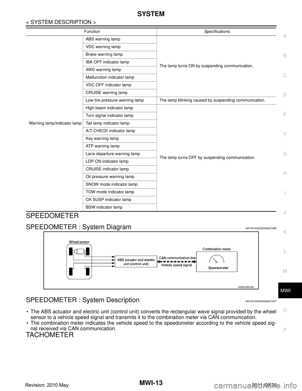
SPEEDOMETER : System DiagramINFOID:0000000006221696
SPEEDOMETER : System DescriptionINFOID:0000000006221697
The ABS actuator and electric unit (control unit) conv erts the rectangular wave signal provided by the wheel
sensor to a vehicle speed signal and transmits it to the combination meter via CAN communication.
The combination meter indicates the vehicle speed to the speedometer according to the vehicle speed sig-
nal received via CAN communication.
TACHOMETER
Warning lamp/indicator lamp ABS warning lamp
The lamp turns ON by suspending communication.
VDC warning lamp
Brake warning lamp
IBA OFF indicator lamp
4WD warning lamp
Malfunction indicator lamp
VDC OFF indicator lamp
CRUISE warning lamp
Low tire pressure warning lamp The lamp blinking caused by suspending communication.
High beam indicator lamp
The lamp turns OFF by suspending communication.
Turn signal indicator lamp
Tail lamp indicator lamp
A/T CHECK indicator lamp
Key warning lamp
AT P w a r n i n g l a m p
Lane departure warning lamp
LDP ON indicator lamp
CRUISE indicator lamp
Oil pressure warning lamp
SNOW mode indicator lamp
TOW mode indicator lamp
CK SUSP indicator lamp
BSW indicator lamp
Function Specifications
JSNIA2382GB
Revision: 2010 May2011 QX56
Page 3759 of 5598

MWI-16
< SYSTEM DESCRIPTION >
SYSTEM
OIL PRESSURE WARNING LAMP : System Description
INFOID:0000000006221709
IPDM E/R reads the ON/OFF signals fr om the oil pressure switch and transmits the oil pressure switch sig-
nal to the combination meter via BCM with the CAN communication.
The combination meter turns the oil pressure warning lamp ON (at the time of a reduction in hydraulic pres-
sure)/OFF (except at the time of a reduction in hydraulic pressure) according to the oil pressure switch signal
received via CAN communication.
MASTER WARNING LAMP
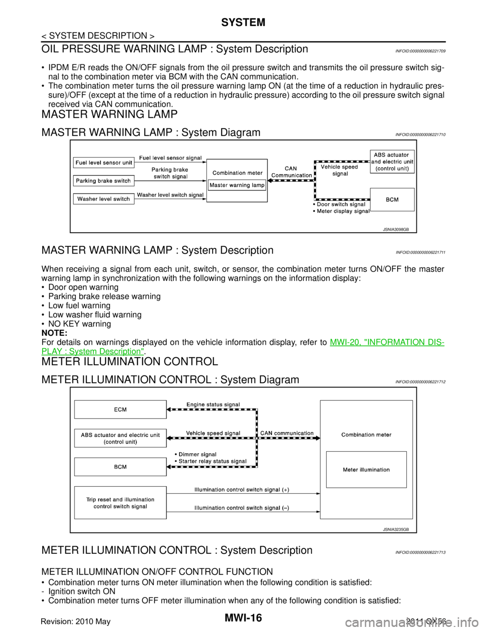
MASTER WARNING LAMP : System DiagramINFOID:0000000006221710
MASTER WARNING LAMP : System DescriptionINFOID:0000000006221711
When receiving a signal from each unit, switch, or s ensor, the combination meter turns ON/OFF the master
warning lamp in synchronization with the following warnings on the information display:
Door open warning
Parking brake release warning
Low fuel warning
Low washer fluid warning
NO KEY warning
NOTE:
For details on warnings displayed on the vehicle information display, refer to MWI-20, "
INFORMATION DIS-
PLAY : System Description".
METER ILLUMINATION CONTROL
METER ILLUMINATION CONTROL : System DiagramINFOID:0000000006221712
METER ILLUMINATION CONTRO L : System DescriptionINFOID:0000000006221713
METER ILLUMINATION ON/OFF CONTROL FUNCTION
Combination meter turns ON meter illumination when the following condition is satisfied:
- Ignition switch ON
Combination meter turns OFF meter illumination when any of the following condition is satisfied:
JSNIA3098GB
JSNIA3235GB
Revision: 2010 May2011 QX56